1
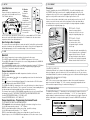
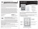
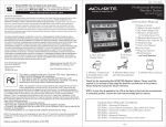
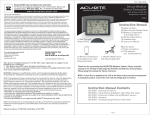
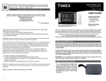
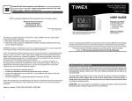
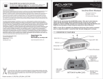
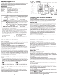
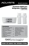
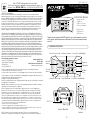
INST - 00986 11011
Please DO NOT return product to the retail store.
For technical assistance and product return information, please call
Customer Care: 877-221-1252 Mon. - Fri. 8:00 A.M. to 4:30 P.M. (CST)
www.chaneyinstrument.com
Refrigerator/Freezer
wireless digital thermometer
#00986
LIMITED ONE YEAR WARRANTY
Chaney Instrument Company warrants that all products it manufactures to be of good material and
workmanship and to be free of defects if properly installed and operated for a period of one year from date of
purchase. REMEDY FOR BREACH OF THIS WARRANTY IS EXPRESSLY LIMITED TO REPAIR OR REPLACEMENT
OF DEFECTIVE ITEMS. Any product which, under normal use and service, is proven to breach the warranty
contained herein within ONE YEAR from date of sale will, upon examination by Chaney, and at its sole option,
be repaired or replaced by Chaney. In all cases, transportation costs and charges for returned goods shall
be paid for by the purchaser. Chaney hereby disclaims all responsibility for such transportation costs and
charges. This warranty will not be breached, and Chaney will give no credit for products it manufactures
which shall have received normal wear and tear, been damaged, tampered, abused, improperly installed,
damaged in shipping, or repaired or altered by others than authorized representatives of Chaney.
THE ABOVE-DESCRIBED WARRANTY IS EXPRESSLY IN LIEU OF ALL OTHER WARRANTIES, EXPRESS OR
IMPLIED, AND ALL OTHER WARRANTIES ARE HEREBY DISCLAIMED, INCLUDING WITHOUT LIMITATION THE
IMPLIED WARRANTY OF MERCHANTABILITY AND THE IMPLIED WARRANTY OF FITNESS FOR A PARTICULAR
PURPOSE. CHANEY EXPRESSLY DISCLAIMS ALL LIABILITY FOR SPECIAL, CONSEQUENTIAL OR INCIDENTAL
DAMAGES, WHETHER ARISING IN TORT OR BY CONTRACT FROM ANY BREACH OF HTIS WARRANT. SOME
STATES DO NOT ALLOW THE EXCLUSIONS OR LIMITATION OF INCIDENTAL OR CONSEQUENTIAL DAMAGES,
SO THE ABOVE LIMITATION OR EXCLUSION MAY NOT APPLY TO YOU. CHANEY FURTHER DISCLAIMS ALL
LIABILITY FROM PERSONAL INJURY RELATING TO ITS PRODUCTS TO THE EXTENT PERMITTED BY LAW. BY
ACCEPTANCE OF ANY OF CHANEY’S EQUIPMENT OR PRODUCTS, THE PURCHASER ASSUMES ALL LIABILITY
FOR THE CONSEQUENCES ARISING FROM THEIR USE OR MISUSE. NO PERSON, FIRM OR CORPORATION
IS AUTHORIZED TO ASSUME FOR CHANEY ANY OTHER LIABILITY IN CONNECTION WITH THE SALE OF ITS
PRODUCTS. FURTHERMORE, NO PERSON, FIRM OR CORPORATION IS AUTHORIZED TO MODIFY OR WAIVE
THE TERMS OF THIS PARAGRAPH, AND THE PRECEDING PARAGRAPH, UNLESS DONE IN WRITING AND
SIGNED BY A DULY AUTHORIZED AGENT OF CHANEY. THIS WARRANTY GIVES YOU SPECIFIC LEGAL RIGHTS,
AND YOU MAY ALSO HAVE OTHER RIGHTS WHICH VARY FROM STATE TO STATE.
For in-warranty repair, please contact:
Customer Care Department
Chaney Instrument Company
965 Wells Street
Lake Geneva, WI 53147
Chaney Customer Care
877-221-1252
Mon-Fri 8:00 a.m. to 4:30 p.m. CST
www.chaneyinstrument.com
This device complies with part 15 of the FCC rules. Operation is subject to the following two conditions:
1- This device may NOT cause harmful interference, and
2- This device must accept any interference received, including interference that may cause undesired operation.
Le présent appareil est conforme aux CNR d’Industrie Canada applicables aux appareils radio exempts de licence.
L’explitation est autorisée aux deux conditions suivantes:
(1) l’appareil ne doit pas produire de brouillage, et
(2) l’utilisateur de l’appareil doit accepter tout brouillage radioélectrique subi, même si le brouillage est susceptible
d’en compromettre le fonctionnement
Instruction Manual
SENSOR 1
MAX
ALARM
MIN
SENSOR 2
F
MAX
CLR
ALARM
MIN
What you need:
(2) AAA Batteries
(4) AA Batteries
1 • OVERVIEW OF FEATURES
Sensor #1 current temp. Low Battery Indicator
Sensor #1
alarm set
SENSOR 1
MAX
Sensor #1 recorded Min/Max
F
Adjust up
ALARM
Adjust down
MIN
SENSOR 2
Sensor #2
alarm set
MAX
ALARM
F
Min/Max
Clear
CLR
MIN
Sensor #2 current temp.
Alarm ON Indicator Sensor #2 recorded Min/Max
FLIP-OUT
TABLE STAND
2
BATTERY
COMPARTMENT
ºF/ºC Select
BATTERY
COMPARTMENT
Magnets
Back of Main Unit
Sensors
NOTE: The manufacturer is not responsible for any radio or TV interference caused by unauthorized
modifications to this equipment. Such modifications could void the user authority to operate the equipment.
-4-
Package Contents:
(1) Main Unit
(2) Wireless Sensors
(1) Instruction Manual
Thank You for purchasing this ACURITE® product. Please read this manual in its entirety
to fully enjoy the benefits and features of this product. Please keep this manual for future
reference.
WARNING: Changes or modifications to this unit not expressly approved by the party responsible for compliance
could void the user’s authority to operate the equipment
NOTE: This equipment has been tested and found to comply with the limits for a Class B digital device,
pursuant to Part 15 of the FCC rules. These limits are designed to provide reasonable protection against
harmfuly interference in a residential installation. This equipment generates, uses and can radiate radio
frequency energy and, if not installed and used in accordance with the instructions, may cause harmful
interference to radio communications. However, there is no guarantee that interference will not occur in a
particular installation. If this equipment does cause harmful interference to radio or television reception,
which can be determined by turning the equipment off and on, the user is interference to radio or television
reception, which can be determined by turning the equipment off and on, the user is encouraged to try to
correct the interference by one or more of the following measures:
• Reorient or relocate the receiving antenna.
• Increase the separation between the equipment and the receiver
• Connect the equipment into an outlet on a circuit different from that to which the receiver is connected.
• Consult the dealer or an experienced radio/TV technician for help.
F
-1-
4 • PLACEMENT
2 • SETUP
Install Batteries
A. Main Unit
Remove the battery compartment cover
on the back of the unit and install 2 fresh
“AAA” Alkaline batteries.
FLIP-OUT
TABLE STAND
BATTERY
COMPARTMENT
B. Wireless Sensors
Remove the
battery
compartment
cover by sliding
it downwards.
Install 2 fresh “AA”
Alkaline batteries
in sensor #1.
Install 2 fresh “AA”
Lithium batteries
in sensor #2.
Placement
2
BATTERY
COMPARTMENT
Sensor #1 should be placed in the REFRIGERATOR. Sensor #2 should be placed in
the FREEZER. (Note: both sensors have the capability of being placed in either the
refrigerator or freezer.) Each sensor is equipped with a spring-action clip with rubber
grips to securely hold the remote unit to the edge of a glass or wire shelf.
Each sensor also includes a detachable suction cup that may be used to secure the #1
remote sensor to the interior surface of the refrigerator. Suction cups do not adhere
to freezing surfaces very well, a remote unit kept in a freezing temperature should be
secured using the integrated spring-clip.
#2 Remote Sensor
shown here mounted to the
interior wire shelf of the freezer
using the integrated spring-clip.
2
#
For the sensor that is placed in the freezer (#2), it is recommended that 2 “AA” lithium
batteries be installed instead of alkaline batteries. Lithium batteries function at lower
temperatures better than alkaline batteries.
#1 Remote Sensor
shown here mounted to
the interior surface of the
refrigerator using the included
suction cup.
Basic Setup is Now Complete
The sensors will soon send a signal to the main unit and the 3 units will be synchronized. It
may take a few minutes for synchronization to be complete. If any of the units appear to be
functioning improperly, refer to the troubleshooting section in this manual.
The main unit may be mounted directly
to the refrigerator surface utilizing the
magnetic back of the unit. The main
unit may also be placed on a table or
other flat surface using the integrated
fold-out stand on the back of the unit.
1
#
3 • USE
Main Unit
Each sensors’ temperature is represented on the main unit in three ways:
The LARGEST numbers displayed are the CURRENT temperature of each sensor.
The two SMALLER numbers to the right in each sensors’ display window are the MINIMUM
and MAXIMUM recorded temperatures.
The recorded MIN/MAX numbers can be cleared by pressing and releasing the “CLR” button.
You may also choose between Fahrenheit or Celsius temperature display by using the
“ºF/ºC Select” switch on the back of the main unit.
Temperature Alarms
The main unit is equipped with an audible temperature alarm for each sensor.
TO SET ALARM
PRESS the alarm button ( or ) for the corresponding sensor to turn the alarm function
ON or OFF.
The “ ALARM ” icon on the main display will appear if the alarm function is ON. If the alarm
icon is NOT displayed, the alarm WILL NOT SOUND.
The ALARM will sound if the temperature of the sensor falls below or rises above the preset
MIN/MAX for more than 15 minutes. This is to prevent “false alarms” from sounding because
the door was opened to load or unload items from a refrigerator or freezer
The alarms are preset with the FDA’s MIN/MAX temperatures for a freezer (sensor #2) and
refrigerator (sensor #1). THE DEFAULT FDA PRESET ALARM TEMPERATURES ARE:
Sensor #1 (REFRIGERATOR): MIN is 33ºF / MAX is 40ºF.
Sensor #2 (FREEZER): MIN is -22ºF / MAX is 0ºF
Temperature Alarms - Programming Customized Presets
3 • OPERATION
Low Battery Indicator
A low battery indicator icon is shown in the display window for each sensor. When the low
battery icon appears, replace the batteries in the sensor with fresh ones. Be sure to never
mix old and new batteries, and never mix battery types such as alkaline and lithium together.
Temperature measurement range:
SENSORS: -40ºF to 158ºF
NOTE: If the sensors are measuring temperatures above the measurable temperature
range the main unit will display “-H-”. If the sensor are measuring temperatures below
the measurable temperature range, the main unit will display “-L-”.
4 • TROUBLESHOOTING
The MAIN UNIT will display “--” when batteries are installed until it acquires the wireless
signal from the sensors. If the main unit still displays “--” or “-E-” the sensors’ batteries
may be dead or the main unit and sensors cannot synchronize wireless signals. Remove all
batteries and follow the setup instructions again, then move the MAIN UNIT to a different
location.
TO CUSTOMIZE THE PRESET ALARM TEMPERATURES
PRESS and hold the desired alarm button ( or ) to view alarm setting, then release.
Set the MAX temperature by using the “+” or “-” buttons.
PRESS the alarm button again to confirm your setting , you will hear a beep.
Set the MIN temperature by using the “+” or “-” buttons.
PRESS the alarm button again to confirm your setting and exit, you will hear a beep.
Repeat this process to set the MIN/MAX alarm temperatures for the other remote sensor.
-2-
-3-