1
BB!H631!.!FO/cppl!!Qbhf!j!!Uvftebz-!Bvhvtu!28-!3115!!5;13!QN
Acer Altos G520 series
User’s guide
BB!H631!.!FO/cppl!!Qbhf!jj!!Uvftebz-!Bvhvtu!28-!3115!!5;13!QN
Copyright © 2004 Acer Incorporated
All Rights Reserved.
Acer Altos G520 series
User’s guide
1st Issue: July 2004
Changes may be made periodically to the information in this publication without obligation
to notify any person of such revision or changes. Such changes will be incorporated in new
editions of this manual or supplementary documents and publications. This company makes
no representations or warranties, either expressed or implied, with respect to the contents
hereof and specifically disclaims the implied warranties of merchantability or fitness for a
particular purpose.
Record the model number, serial number, purchase date, and place of purchase information in
the space provided below. The serial number and model number are recorded on the label
affixed to your computer. All correspondense concerning your unit should include the serial
number, model number, and purchase information.
No part of this publication may be reproduced, stored in a retrieval system, or transmitted, in
any form or by any means, electronic, mechanical, photocopy, recording, or otherwise,
without the prior written permission of Acer Incorporated.
Model Number : _________________________________
Serial Number: ___________________________________
Purchase Date: ___________________________________
Place of Purchase: ________________________________
Acer and the Acer logo are registered trademarks of Acer Inc. Other company’s product
names or trademarks are used herein for identification purposes only and belong to their
respective companies.
BB!H631!.!FO/cppl!!Qbhf!jjj!!Uvftebz-!Bvhvtu!28-!3115!!5;13!QN
iii
Notices
FCC notice
Class A devices do not have an FCC logo or FCC IDE on the label. Class B devices
have an FCC logo or FCC IDE on the label. Once the class of the device is
determined, refer to the following corresponding statement.
Class B equipment
This device has been tested and found to comply with the limits for a Class B
digital device pursuant to Part 15 of the FCC Rules. These limits are designed to
provide reasonable protection against harmful interference in a residential
installation. This device generates, uses, and can radiate radio frequency
energy, and if not installed and used in accordance with the instructions, may
cause harmful interference to radio communications.
However, there is no guarantee that interference will not occur in a particular
installation. If this device does cause harmful interference to radio or television
reception, which can be determined by turning the device off and on, the user
is encouraged to try to correct the interference by one or more of the following
measures:
•
Reorient or relocate the receiving antenna
•
Increase the separation between the device and receiver
•
Connect the device into an outlet on a circuit different from that to which
the receiver is connected
•
Consult the dealer or an experienced radio/television technician for help
Notice: Shielded cables
All connections to other computing devices must be made using shielded cables
to maintain compliance with FCC regulations.
Notice: Peripheral devices
Only peripherals (input/output devices, terminals, printers, etc.) certified to
comply with the Class A or Class B limits may be attached to this equipment.
Operation with noncertified peripherals is likely to result in interference to
radio and TV reception.
Caution! Changes or modifications not expressly approved by the
manufacturer could void the user’s authority, which is granted by
the Federal Communications Commission, to operate this server.
BB!H631!.!FO/cppl!!Qbhf!jw!!Uvftebz-!Bvhvtu!28-!3115!!5;13!QN
iv
Use conditions
This part complies with Part 15 of the FCC Rules. Operation is subject to the
following two conditions: (1) this device may not cause harmful interference,
and (2) this device must accept any interference received, including interference
that may cause undesired operation.
Notice: Canadian users
This Class A/Class B digital apparatus meets all requirements of the Canadian
Interference-Causing Equipment Regulations.
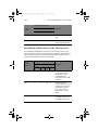
Laser compliance statement
The CD-ROM drive in this server is a laser product. The CD-ROM drive’s
classification label (shown below) is located on the drive.
CLASS 1 LASER PRODUCT
CAUTION: INVISIBLE LASER RADIATION WHEN OPEN. AVOID EXPOSURE TO
BEAM.
BB!H631!.!FO/cppl!!Qbhf!w!!Uvftebz-!Bvhvtu!28-!3115!!5;13!QN
v
Important safety instructions
Read these instructions carefully. Save these instructions for future reference.
1
Follow all warnings and instructions marked on the product.
2
Unplug this product from the wall outlet before cleaning. Do not use
liquid cleaners or aerosol cleaners. Use a damp cloth for cleaning.
3
Do not use this product near water.
4
Do not place this product on an unstable cart, stand, or table. The product
may fall, causing serious damage to the product.
5
Slots and openings on the back or bottom side of the chassis are provided
for ventilation; to ensure reliable operation of the product and to protect
it from overheating, these openings must not be blocked or covered. The
openings should never be blocked by placing the product on a bed, sofa,
rug, or other similar surface. This product should never be placed near or
over a radiator or heat register, or in a built-in installation unless proper
ventilation is provided.
6
This product should be operated from the type of power indicated on the
marking label. If you are not sure of the type of power available, consult
your dealer or local power company.
7
Do not allow anything to rest on the power cord. Do not locate this
product where persons will walk on the cord.
8
If an extension cord is used with this product, make sure that the total
ampere rating of the equipment plugged into the extension cord does not
exceed the extension cord ampere rating. Also, make sure that the total
rating of all products plugged into the wall outlet does not exceed the fuse
rating.
9
Never push objects of any kind into this product through chassis slots as
they may touch dangerous voltage points or short out parts that could
result in a fire or electric shock. Never spill liquid of any kind on the
product.
10
Do not attempt to service this product yourself, as opening or removing
covers may expose you to dangerous voltage points or other risks. Refer all
servicing to qualified service personnel.
11
Unplug this product from the wall outlet and refer servicing to qualified
service personnel under the following conditions:
a
When the power cord or plug is damaged or frayed
b
If liquid has been spilled into the product
c
If the product has been exposed to rain or water
BB!H631!.!FO/cppl!!Qbhf!wj!!Uvftebz-!Bvhvtu!28-!3115!!5;13!QN
vi
d
If the product does not operate normally when the operating
instructions are followed. Adjust only those controls that are covered
by the operating instructions since improper adjustment of other
controls may result in damage and will often require extensive work
by a qualified technician to restore the product to normal condition.
e
If the product has been dropped or the cabinet has been damaged
f
If the product exhibits a distinct change in performance, indicating a
need for service.
12
Replace the battery with the same type as the product's battery we
recommend. Use of another battery may present a risk of fire or explosion.
Refer battery replacement to a qualified service technician.
13
Warning! Batteries may explode if not handled properly. Do not
disassemble or dispose of them in fire. Keep them away from children and
dispose of used batteries promptly.
14
Use only the proper type of power supply cord set (provided in your
accessories box) for this unit. It should be a detachable type: UL listed/CSA
certified, type SPT-2, rated 7A 125V minimum, VDE approved or its
equivalent. Maximum length is 15 feet (4.6 meters).
Notices
FCC notice
Laser compliance statement
Important safety instructions
iii
iii
iv
v
1 System tour
1
Product briefing
Processor
Memory subsystem
Storage
Graphics interface
Networking
I/O ports
Serial ATA ports
Caring features
Product specification summary
External and internal structure
Front bezel
Front panel
Rear panel
Internal components
System boards
Mainboard layout
Hot Plug HDD Cage backplane board layout (SCSI)
Hot Plug HDD Cage backplane board layout (SATA)
2 System setup
Setting up the system
Preinstallation requirements
Connecting peripherals
To connect the PS/2 keyboard
To connect the PS/2 mouse
To connect the VGA monitor
To connect the power cable
Turning on the system
Power-on problems
Operating system configuration
Network connection
Tower-to-rack option
Turning off the system
3
3
3
3
4
4
4
4
5
6
7
7
8
10
12
14
14
17
18
21
23
23
24
24
25
26
27
28
29
30
31
32
33
Contents
BB!H631!.!FO/cppl!!Qbhf!wjj!!Uvftebz-!Bvhvtu!28-!3115!!5;13!QN
BB!H631!.!FO/cppl!!Qbhf!wjjj!!Uvftebz-!Bvhvtu!28-!3115!!5;13!QN
3 Upgrading the system
Upgrading the system
Installation precautions
Opening the server
Before opening the server
To open the front bezel
To remove the front bezel
To remove the side panel
Configuring the Hot Plug HDD cage
To remove the Hot Plug HDD cage
To install a hard disk into the carrier
To install the Hot Plug HDD cage
Configuring the non-Hot Plug HDD cage
To remove the cage
To install a hard disk into the cage
To install the cage
Installing and removing storage devices
To remove a 5.25-inch storage device
To install a 5.25-inch storage device
Upgrading the CPU
To remove a CPU with heatsink
Processor Sequence
To install a CPU with heatsink
Upgrading the system memory
To remove a DIMM
To install a DIMM
Replacing the Backup Battery
Installing an expansion card
To install an expansion card
Installing a redundant power supply module
To install a redundant power supply module
4 BIOS setup
BIOS setup
Entering BIOS setup
Main
Advanced
Processor Summary and Configuration
IDE Configuration
Floppy Configuration
Super I/O Configuration
USB Configuration
PCI Configuration
35
37
37
39
39
39
39
41
43
43
45
46
49
49
50
51
52
52
53
55
55
56
56
59
60
60
62
64
64
66
67
69
71
72
74
76
77
78
83
84
85
87
BB!H631!.!FO/cppl!!Qbhf!jy!!Uvftebz-!Bvhvtu!28-!3115!!5;13!QN
Memory Configuration
Boot
Boot Settings Configuration
Boot Device Priority
Hard Disk Drives
Removable Devices
ATAPI CD/DVD Devices
Security
To set an Administrator/User password
To remove the User password
Server
System Management
Serial Console Features
Event Log Configuration
Exit
Upgrading the BIOS
Preparing for the Upgrade
Recording the Current BIOS Settings
Obtaining the Upgrade
Creating a Bootable Diskette
Creating the BIOS Upgrade Diskette
Upgrading the BIOS
Changing the BIOS Language
Recovering the BIOS
Manually Recovering the BIOS
Clearing the CMOS
Clearing the Password
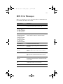
BIOS Error Messages
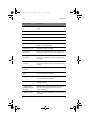
BIOS POST Beep Codes
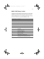
BIOS Recovery Beep Codes
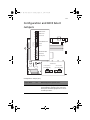
Configuration and BIOS Select Jumpers
Appendix A: Troubleshooting
Resetting the System
Problems following Initial System Installation
First Steps Checklist
Hardware Diagnostic Testing
Verifying Proper Operation of Key System Lights
Confirming Loading of the Operating System
Specific Problems and Corrective Actions
Power Light Does Not Light
No Characters Appear on Screen
Characters Are Distorted or Incorrect
88
90
91
92
94
95
96
97
99
99
100
102
103
105
107
109
109
109
109
110
110
110
112
112
112
113
114
115
117
229
119
121
123
123
123
124
125
125
126
126
127
128
BB!H631!.!FO/cppl!!Qbhf!y!!Uvftebz-!Bvhvtu!28-!3115!!5;13!QN
System Cooling Fans Do Not Rotate Properly
Diskette Drive Activity Light Does Not Light
Optical Drive Activity Light Does Not Light
Cannot Connect to a Server
Problems with Network
System Boots when Installing PCI Card
Problems with Newly Installed Application Software
Problems with Application that Ran Correctly Earlier
Hard Drive(s) are not Recognized
Bootable CD-ROM Is Not Detected
LED Information
128
129
129
130
130
131
131
132
132
133
133
Appendix B: ASM Quick Installation Guide135
Installing ASM
System requirements
System setup
137
137
137
Appendix C: Altos G520 Rack Installation Guide139
System rack installation
Vertical mounting hole pattern
Screw types for rack installation
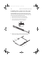
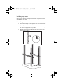
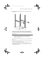
Installing the system into the rack
Appendix D: SATA RAID Configuration
Configuring the onboard SATA RAID
How to enable the onboard SATA RAID function
How to create RAID 1 volume
Loading onboard SATA RAID default setting
141
142
143
144
147
149
149
149
149
Appendix E: RAID Configuration
153
Configuring the SCSI/SCSI RAID HBA
How to use SCSI HBA setup utility
How to use SCSI RAID HBA setup utility
MegaRAID Configuration Utility
155
155
155
156
Appendix F: Diagnostic Code Checkpoints 159
POST Code Checkpoints
Bootblock Initialization Code Checkpoints
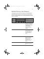
Bootblock Recovery Code Checkpoint
Index
161
168
171
175
BB!H631!.!FO/cppl!!Qbhf!2!!Uvftebz-!Bvhvtu!28-!3115!!5;13!QN
1 System tour
BB!H631!.!FO/cppl!!Qbhf!3!!Uvftebz-!Bvhvtu!28-!3115!!5;13!QN
The Acer Altos G520 series server is a
powerful dual-processor system loaded with
a host of new and innovative features. The
system offers a new standard for flexible
productivity ideal for general business
applications, email, web service and print
services.
BB!H631!.!FO/cppl!!Qbhf!4!!Uvftebz-!Bvhvtu!28-!3115!!5;13!QN
3
Product briefing
This section provide basic information concerning the configuration of
your Altos G520 system.
Processor
•
Single or dual Intel® Xeon™ processor with 800 MHz FSB
•
Intel® Hyper-Threading™ Technology support
Memory subsystem
•
Four (184 - pin) DIMM slots
•
DDR 333/400 MHz ECC Register, Buffered memory modules
supported
•
Maximum upgrade - 8 GB
Warning! Functionality issues may be encountered if mixed
memory types are installed on the same server board. DIMM
modules of identical type, banking and stacking technology, and
vendor should be installed in the Altos G520.
Caution! When using multiple memory modules it is
recommended that you AVOID using modules from different
manufacturers or that run at different speeds from each other.
Note: 333 MHz memory will run at 320 MHz when used with a
processor with 800 MHz system bus frequency.
Storage
•
5.25 inch IDE CD-ROM drive
•
3.5 inch Floppy disk drive
•
Support for three (max) hard disk drives
•
•
Four additional 5.25 Inch device bays for add-on options such as:
DDS4 DAT 20/40 GB tape backup drive
BB!H631!.!FO/cppl!!Qbhf!5!!Uvftebz-!Bvhvtu!28-!3115!!5;13!QN
4
1 System tour
•
•
•
DAT72 36/72 GB tape backup drive
AIT1 35/91 GB tape backup drive
DVD-ROM, DVD-RW, DVD-Dual or other optical drive
Graphics interface
•
On-board ATI RageXL PCI Video with 8MB memory
Networking
•
Single Gigabit Ethernet port
I/O ports
•
•
Front
Two USB 2.0 ports
•
•
•
•
•
Rear
Four USB 2.0 ports
Two PS/2 ports (keyboard/mouse)
One LAN port (RJ-45)
One parallel port
Two serial ports
•
Serial ATA ports
•
Two serial ATA ports supporting RAID 0 or RAID 1
BB!H631!.!FO/cppl!!Qbhf!6!!Uvftebz-!Bvhvtu!28-!3115!!5;13!QN
5
Caring features
Part of Acer’s mission, as a company that cares about its end users, is to
provide features that make operation, maintenance, and upgrading
your system simpler and faster. The Altos G520 is no exception to this
rule. The following features and options are provided.
•
Cost efficient operation in a value oriented package.
•
Front accessible USB ports.
•
Acer EasyBUILD
•
Acer Server Manager (ASM) suite of comprehensive management
tools.
TM
for efficient system setup and installation.
BB!H631!.!FO/cppl!!Qbhf!7!!Uvftebz-!Bvhvtu!28-!3115!!5;13!QN
6
1 System tour
Product specification summary
Highlighted below are the system’s key features:
•
Single or dual Intel Xeon
•
Intel E7320 core logic chipset consisting of:
•
Intel 827320 Memory Controller Hub (MCH)
•
Intel 6300ESB I/O Controller Hub (ICH)
®
TM
processor supporting 800 MHz FSB
®
®
®
•
Intel 82541 Platform LAN Connect (PLC) device for 10/100/1000
Mbits/sec Ethernet LAN
•
Dual on-board SATA 150 ports
•
Five PCI bus slots with three separate bus segments
•
One PCI-Express X4 bus slot
•
Two 64-bit/66 MHz PCI-X bus slots
•
Two 32-bit/33 MHz PCI bus slot
•
ATI Rage XL video controller with 8 MB SDRAM
•
Four DIMM sockets supporting ECC 266/333 MHz DDR modules for
a maximum memory capacity of 8 GB
•
Media storage
•
3.5-inch, 1.44 MB floppy drive
•
IDE CD-ROM drive
•
Additional media storage capacity
•
Hot Plug HDD cage
• supporting up to four 3.5 inch SCSI Ultra320 15K rpm 80pin
drives
• supporting up to four 3.5 inch SATA 150/300 10K rpm drives
•
Non-Hot Plug HDD cage
• supporting up to four 3.5 inch 68pin SCSI drives
• supporting up to four 3.5 inch SATA 150/300 drives
•
External ports
• PS/2 keyboard/mouse ports
• One Serial/VGA (monitor) port
• Four USB 2.0 ports
• One LAN port
•
Power supply unit (PSU)
•
610-watt 1+0/1+1 redundant power supply subsystem (with
power distribution board).
•
600-watt single standard (non-redundant) power supply.
®
BB!H631!.!FO/cppl!!Qbhf!8!!Uvftebz-!Bvhvtu!28-!3115!!5;13!QN
7
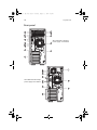
External and internal structure
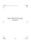
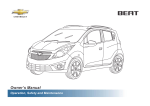
Front bezel
Note: One pair of system keys are attached to the rear panel. .
No.
Description
No.
Description
1
Front bezel
2
Security keylock
3
System power indicator
4
Hard disk activity indicator
5
Fault indicator
6
LAN1 activity indicator
BB!H631!.!FO/cppl!!Qbhf!9!!Uvftebz-!Bvhvtu!28-!3115!!5;13!QN
8
1 System tour
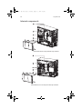
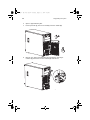
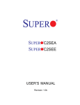
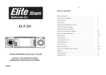
Front panel
Altos G520 with Hot Plug hard disk
cage installed.
Altos G520 with non-Hot Plug hard
disk cage installed.
BB!H631!.!FO/cppl!!Qbhf!:!!Uvftebz-!Bvhvtu!28-!3115!!5;13!QN
9
No.
Description
1
CD-ROM drive Stop/Eject button
2
CD-ROM drive activity indicator
3
CD-ROM drive
4
Volume control
5
CD-ROM drive Headphone/Earphone port
6
5.25-inch half-height drive bay
7
Hot Plug hard disk cage -or- Non-Hot Plug hard disk cage
(manufacturing optional)
8
HDD carrier (for Hot Plug HDD Cage only)
9
Floppy drive activity indicator
10
Floppy drive
11
Floppy drive Eject button
12
Hot Plug HDD power indicator 1 (for Hot Plug HDD cage only)
13
Hot Plug HDD access indicator 2 (for Hot Plug HDD cage only)
14
Power button
15
System power indicator
16
Hard disk activity indicator
17
System fault indicator
18
LAN activitiy indicator
1 This indicator lights up green to indicate HDD power on and lights up in red when a
HDD fault occurs.
2 This indicator lights up green to indicate drive access.
3 When system is degraded or faulty,the status indicator would blink or light up amber.
.
BB!H631!.!FO/cppl!!Qbhf!21!!Uvftebz-!Bvhvtu!28-!3115!!5;13!QN
10
1 System tour
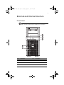
Rear panel
Altos G520 with redundant
power supply unit installed.
Altos G520 with fixed single
power supply unit installed.
BB!H631!.!FO/cppl!!Qbhf!22!!Uvftebz-!Bvhvtu!28-!3115!!5;13!QN
11
No.
Icon
Description
1
Main power supply cable socket
2
USB ports
3
PS/2 keyboard port
4
PS/2 mouse port
5
VGA/monitor port
6
Serial port
7
8
Gigabit LAN port (10/100/1000 Mbps)
9
Expansion slots
10
Main power supply indicator 1
11
Main power supply fail indicator 2
12
Main standard 600-watt power supply unit (PSU)
13
Rear system fan
14
Side Panel lock release
1 This indicator will light up green when the power supply module is functioning properly.
2 This indicator will light up amber when the power supply module or any PSU internal fan
fails.
BB!H631!.!FO/cppl!!Qbhf!23!!Uvftebz-!Bvhvtu!28-!3115!!5;13!QN
12
1 System tour
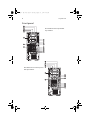
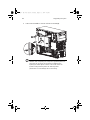
Internal components
Altos G520 with Hot Plug hard disk cage installed.
Altos G520 with non-Hot Plug hard disk cage installed.
BB!H631!.!FO/cppl!!Qbhf!24!!Uvftebz-!Bvhvtu!28-!3115!!5;13!QN
13
No.
Description
1
Power supply module bays for two redundant PSUs 1 -orone single standard PSU bay (Manufacturing optional)
2
Rear system fan
3
Rear system fan screw (to secure the rear system fan)
4
Mainboard
5
PCI bus slot
6
Air baffle
1 Though the system supports two hot-swappable power supply modules, the system comes bundled with a single standard 600-watt power supply module only.
You have the option to purchase an extra power supply module to provide the system with a redundant power source.
BB!H631!.!FO/cppl!!Qbhf!25!!Uvftebz-!Bvhvtu!28-!3115!!5;13!QN
14
1 System tour
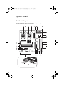
System boards
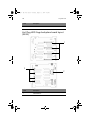
Mainboard layout
The mainboard becomes accessible once you open the system. It
should look like the figure shown below.
BB!H631!.!FO/cppl!!Qbhf!26!!Uvftebz-!Bvhvtu!28-!3115!!5;13!QN
15
Note: Unless otherwise indicated, all mainboard features
indicated on the table below apply to both the Altos G520 and
Altos G520 Basic models.
Item
Description
A
64-bit/66 MHz PCI-X bus slot 1
B
64-bit/66 MHz PCI-X bus slot 2
C
ATI Rage XL VGA chipset
D
32-bit/33 MHz PCI bus slot 3
E
x4 PCI-Express slot 4
F
Gigabit LAN chipset
G
32-bit/33 MHz PCI bus slot 5
H
Gigabit LAN port (10/100/1000 Mbps)
I
VGA/monitor port
J
Serial port
K
Upper: PS/2 mouse port
Lower: PS/2 keyboard port
L
USB ports
M
Auxilliary power connector
N
Main power connector
O
Rear system fan headers (two)
P
DIMM slots
Q
+12V CPU power connector
R
Intel® E7320 MCH chipset
S
CPU socket 1
BB!H631!.!FO/cppl!!Qbhf!27!!Uvftebz-!Bvhvtu!28-!3115!!5;13!QN
16
1 System tour
Item
Description
US
CPU 1 fan header
T
CPU socket 2
UT
CPU 2 fan header
V
ATA power connector
W
BIOS select jumper
X
IPMB connector
Y
Floppy drive connector
Z
Primary and Secondary ATA connector
AA
Front system fan header
BB
Front panel connector
CC
Front panel USB header
DD
ARMC connector
EE
SATA A1 and A2 connectors
FF
Intel® 6300ESB ICH (ICH5 HR)
GG
Chassis Intrusion header
HH
Jumper Block
1-3 CMOS Clear
5-7 Password Clear
9-11 Recovery Boot
II
Serial B header
JJ
SCSI LED connector
KK
Battery
BB!H631!.!FO/cppl!!Qbhf!28!!Uvftebz-!Bvhvtu!28-!3115!!5;13!QN
17
Hot Plug HDD Cage backplane board layout
(SCSI)
Label
Description
1
122-pin SAF-TE connector
2
80-pin SCSI HDD connector
3
68-pin SCSI HDD connector
4
SCSI HDD management cable connector (I2C bus)
BB!H631!.!FO/cppl!!Qbhf!29!!Uvftebz-!Bvhvtu!28-!3115!!5;13!QN
18
1 System tour
Label
Description
5
Power connector
Hot Plug HDD Cage backplane board layout
(SATA)
1
2
3
Label
Description
1
SATA HDD slot
BB!H631!.!FO/cppl!!Qbhf!2:!!Uvftebz-!Bvhvtu!28-!3115!!5;13!QN
19
Label
Description
2
SATA cable connector
3
HDD backplane power connector (10pin)
BB!H631!.!FO/cppl!!Qbhf!31!!Uvftebz-!Bvhvtu!28-!3115!!5;13!QN
20
1 System tour
BB!H631!.!FO/cppl!!Qbhf!32!!Uvftebz-!Bvhvtu!28-!3115!!5;13!QN
2 System setup
BB!H631!.!FO/cppl!!Qbhf!33!!Uvftebz-!Bvhvtu!28-!3115!!5;13!QN
This chapter gives you instructions on how to set up
the system. Procedures on how to connect
peripherals are also explained.
BB!H631!.!FO/cppl!!Qbhf!34!!Uvftebz-!Bvhvtu!28-!3115!!5;13!QN
23
Setting up the system
Preinstallation requirements
Selecting a site
Before unpacking and installing the system, select a suitable site for
the system for maximum efficiency. Consider the following factors
when choosing a site for the system:
•
Near a grounded power outlet
•
Clean and dust-free
•
Stable surface free from vibration
•
Well-ventilated and away from sources of heat
•
Secluded from electromagnetic fields produced by electrical
devices such as air conditioners, radio and TV transmitters, etc.
Checking the package contents
Check the following items from the package:
•
Acer Altos G520 series system
•
Acer Altos G520 series User’s guide
•
Acer EasyBUILD
•
Acer Altos G520 series Accessory box
•
System keys (attached to the rear panel of the system)
TM
If any of the above items are damaged or missing, contact your dealer
immediately.
Save the boxes and packing materials for future use.
BB!H631!.!FO/cppl!!Qbhf!35!!Uvftebz-!Bvhvtu!28-!3115!!5;13!QN
24
2 System setup
Connecting peripherals
The system unit, keyboard, mouse, and monitor constitute the basic
system. Before connecting any other peripherals, connect these basic
peripherals first to test if the system is running properly.
Note: Unless otherwise indicated, all illustrations shown in this
section show the Altos G520 server chassis.
To connect the PS/2 keyboard
Plug the keyboard cable into the PS/2 keyboard port
port) located on the rear panel of the server.
(purple
BB!H631!.!FO/cppl!!Qbhf!36!!Uvftebz-!Bvhvtu!28-!3115!!5;13!QN
25
To connect the PS/2 mouse
Plug the PS/2 mouse cable into the PS/2 mouse port
located on the rear panel of the server.
(green port)
BB!H631!.!FO/cppl!!Qbhf!37!!Uvftebz-!Bvhvtu!28-!3115!!5;13!QN
26
2 System setup
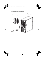
To connect the VGA monitor
To connect the VGA monitor, simply plug the monitor cable into the
VGA/monitor port
server.
(blue port) located on the rear panel of the
BB!H631!.!FO/cppl!!Qbhf!38!!Uvftebz-!Bvhvtu!28-!3115!!5;13!QN
27
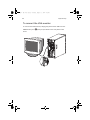
To connect the power cable
Plug the power cable into the power cable socket located on the rear
panel of the server. Then plug the other end of the power cable into a
power outlet. The figure below shows the Altos G520 Basic model.
BB!H631!.!FO/cppl!!Qbhf!39!!Uvftebz-!Bvhvtu!28-!3115!!5;13!QN
28
2 System setup
Turning on the system
After making sure that you have properly set up the system and
connected all the required cables, you can now power on the system.
To power on the system, press the power button on the front panel.
The system starts up and displays a welcome message. After that, a
series of power-on self-test (POST) messages appears. The POST
messages indicate if the system is running well or not.
Note: The illustration below shows the Altos G520 server chassis.
Note: If the system does not turn on or boot after pressing the
power button, go to the next section for the possible causes of the
boot failure.
Aside from the POST messages, you can determine if the system is in
good condition by checking if the following occurred:
•
Power indicator on the front panel lights up (green)
•
Num Lock, Caps Lock, and Scroll Lock indicators on the keyboard
light up
BB!H631!.!FO/cppl!!Qbhf!3:!!Uvftebz-!Bvhvtu!28-!3115!!5;13!QN
29
Power-on problems
If the system does not boot after you have applied power, check the
following factors that might have caused the boot failure.
•
The external power cable may be loosely connected.
Check the power cable connection from the power source to the
power cable socket on the rear panel. Make sure that the cable is
properly connected to the power source and to the power cable
socket.
•
No power comes from the grounded power outlet.
Have an electrician check your power outlet.
•
Loose or improperly connected internal power cables.
Check the internal cable connections. If you are not confident to
perform this step, ask a qualified technician to assist you.
Warning! Make sure all power cords are disconnected from the
electrical outlet before performing this task.
Note: If you have gone through the preceding actions and the
system still fails to boot, ask your dealer or a qualified technician
for assistance.
BB!H631!.!FO/cppl!!Qbhf!41!!Uvftebz-!Bvhvtu!28-!3115!!5;13!QN
30
2 System setup
Operating system configuration
The Acer Altos G520 series server comes with Acer EasyBUILD that
allows you to conveniently install your choice of operating system. To
start using EasyBUILD, follow the steps below.
TM
1
Locate the EasyBUILD System CD included in the system package.
2
With your system powered on, gently press the optical drive Stop/
Eject button.
3
When the disc tray slides open, insert the EasyBUILD System CD
with the label or title side of the disc facing upward.
Note: When handling the disc, hold it by the edges to avoid
smudges or fingerprints.
4
Gently press the disc down to make sure that it is properly
inserted.
Caution! While pressing the disc, be careful not to bend the disc
tray. Make sure that the disc is properly inserted before closing
the disc tray. Improper insertion may damage both the disc and
the optical drive.
5
Gently press the drive Stop/Eject button again to close the disc
tray.
6
The Acer EasyBUILD sequence begins automatically. Follow all
onscreen instructions.
For more information, refer to the EasyBUILD
TM
Installation guide.
BB!H631!.!FO/cppl!!Qbhf!42!!Uvftebz-!Bvhvtu!28-!3115!!5;13!QN
31
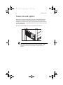
Network connection
The server has one 10/100/1000 Mbps Gigabit Etherned LAN port
located on the rear panel for fast network connection.
To connect to the network, simply plug the network cable into the
Gigabit LAN port
(gray port).
Note: The illustration below shows the Altos G520 Basic server
chassis.
Note: Consult the operating system manual for information on
how to configure the network setup.
BB!H631!.!FO/cppl!!Qbhf!43!!Uvftebz-!Bvhvtu!28-!3115!!5;13!QN
32
2 System setup
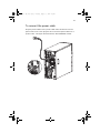
Tower-to-rack option
Aside from its tower configuration, the Acer Altos G520 series server
can also be mounted in a rack-model position. A rack mount kit is
available for customers who want to convert a tower-mounted system
to rack-model design. To purchase a rack mount kit, contact your local
Acer representative.
The figure below shows the server in a rack-mount position.
Note: The illustration above shows the Altos G520 server chassis.
Rack Mount instructions are provided as an appendix to this
manual.
BB!H631!.!FO/cppl!!Qbhf!44!!Uvftebz-!Bvhvtu!28-!3115!!5;13!QN
33
Turning off the system
To turn off the server, on the Windows taskbar click on the Start
button, point to Shut Down..., select Shut down from the
drop-down window then click on OK. You can then turn off all
peripherals connected to your server.
If you are unable to shutdown the server within Windows, press and
hold the power button for at least four seconds to force quit all
applications and shut down.
BB!H631!.!FO/cppl!!Qbhf!45!!Uvftebz-!Bvhvtu!28-!3115!!5;13!QN
34
2 System setup
BB!H631!.!FO/cppl!!Qbhf!46!!Uvftebz-!Bvhvtu!28-!3115!!5;13!QN
3 Upgrading
the system
BB!H631!.!FO/cppl!!Qbhf!47!!Uvftebz-!Bvhvtu!28-!3115!!5;13!QN
This chapter discusses the precautionary
measures and installation procedures you
need to know when upgrading the system.
BB!H631!.!FO/cppl!!Qbhf!48!!Uvftebz-!Bvhvtu!28-!3115!!5;13!QN
37
Upgrading the system
Certain components of the server are upgradeable such as the drives,
the CPU, the memory, and the expansion cards. However, for safety
purposes, we do not recommend that you perform these upgrades
yourself. If you want to replace or upgrade any of these components,
contact your dealer or a qualified service technician for assistance.
Important: Observe the installation precautions described in the
subsequent section when installing or removing a server
component.
Installation precautions
Before you install any server component, we recommend that you read
the following sections. These sections contain important ESD
precautions along with preinstallation and post-installation
instructions.
ESD precautions
Electrostatic discharge (ESD) can damage the processors, motherboard,
disk drives, expansion boards, or other components. Always observe
the following precautions before you install a server component:
1
Do not remove a component from its protective packaging until
you are ready to install it.
2
Wear a wrist grounding strap and attach it to a metal part of the
server before handling components. If a wrist strap is not
available, maintain contact with the server throughout any
procedure requiring ESD protection.
Preinstallation instructions
Always observe the following before you install any component:
1
Turn off the system and all the peripherals connected to it.
2
Unplug all cables from the power outlets.
BB!H631!.!FO/cppl!!Qbhf!49!!Uvftebz-!Bvhvtu!28-!3115!!5;13!QN
38
3 Upgrading the system
3
Open the system according to the instructions beginning on page
39.
4
Follow the ESD precautions described in this section when
handling a server component.
5
Remove any expansion board(s) or peripheral(s) that block access
to the DIMM socket or other component connector.
See the following sections for specific installation instructions on the
component you want to install.
Warning! Failure to properly turn off the server before you start
installing components may cause serious damage. Do not attempt
the procedures described in the following sections unless you are
a qualified service technician.
Post-installation instructions
Observe the following after installing a server component:
1
See to it that all components are installed according to the
described step-by-step instructions.
2
Reinstall any expansion board(s) or peripheral(s) that you have
previously removed.
3
Reinstall the air baffle.
4
Reinstall the chassis panels.
5
Connect the necessary cables.
6
Turn on the system.
BB!H631!.!FO/cppl!!Qbhf!4:!!Uvftebz-!Bvhvtu!28-!3115!!5;13!QN
39
Opening the server
Caution! Before you proceed, make sure that you have turned off
your system and all peripherals connected to it. Read the
“Preinstallation instructions” on page 37.
You need to open the server before you can install additional
components. The front bezel and left side panel are removable to
allow access to the system’s internal components. Refer to the
following sections for instructions.
Before opening the server
Before opening the server, observe the following precautions:
1
Turn off the system and all the peripherals connected to it.
2
Unplug all cables from the power outlets.
3
Place the system unit on a flat, stable surface.
Note: The illustrations used in this section show the Altos G520
server chassis.
To open the front bezel
A security lock secures the front bezel to protect your system unit
against unauthorized access.
To open the front bezel:
1
Insert the key into the lock and turn it clockwise until it points to
the unlocked icon .
2
Open the front bezel.
To remove the front bezel
The front bezel is attached to the chassis by screwless hinges.
To remove the front bezel:
1
Unlock the bezel with the key (when necessary).
BB!H631!.!FO/cppl!!Qbhf!51!!Uvftebz-!Bvhvtu!28-!3115!!5;13!QN
40
3 Upgrading the system
2
Open it approximately 90°.
3
Lift it up a little (1), then move it away from the chassis (2).
4
Remove the upper bezel assembly by pressing the two finger
releases (1), then lift from the bottom (2) and remove.
BB!H631!.!FO/cppl!!Qbhf!52!!Uvftebz-!Bvhvtu!28-!3115!!5;13!QN
41
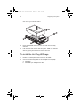
To remove the side panel
The side panel is attached to the server by two (non-removeable)
thumbscrews.
To remove the side panel:
1
Loosen the thumbscrews located at the end of the left panel
closest to the rear panel (1).
2
Slide the left panel slightly rearward (2), then upward (3) before
detaching it from the chassis (4).
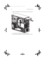
To remove the air baffle
Remove the air baffle to allow easy access to the motherboard and
system components.
Follow the steps below to remove the air baffle:
1
Remove the two screws (four total) at either end of the air
baffle (1). Save the screws for later use.
BB!H631!.!FO/cppl!!Qbhf!53!!Uvftebz-!Bvhvtu!28-!3115!!5;13!QN
42
2
3 Upgrading the system
Pull out the air baffle to remove it from the chassis (2).
Caution! After completing the component upgrade/replacement
procedures, do not forget to reinstall the air baffle before
replacing the chassis panels. Failure to do so will reduce the
system’s cooling efficiency which can adversely affect
performance or cause damage due to overheating.
BB!H631!.!FO/cppl!!Qbhf!54!!Uvftebz-!Bvhvtu!28-!3115!!5;13!QN
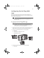
43
Configuring the Hot Plug HDD
cage
This section includes instructions for removing and installing the
Hot Plug HDD cage as well as procedures on how to install a hard disk
into the cage’s hard disk carrier.
Note: The Hot Plug HDD cage feature is only applicable to the
Altos G520 model.
To remove the Hot Plug HDD cage
Important: Before detaching the Hot Plug HDD cage from the
chassis, make sure to first remove all hard disks from their carriers.
For instructions, refer to the succeeding section.
1
Remove the two parts of the front bezel, the side panel and the air
baffle. Refer to the previous section for detailed intructions.
2
Disconnect the following cables from the cage (SCSI):
3
a
SCSI cable
b
SCSI HDD 6 pin management cable
c
SCSI HDD power cable
Disconnect the following cables from the cage (SATA):
a
SATA cable
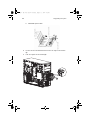
BB!H631!.!FO/cppl!!Qbhf!55!!Uvftebz-!Bvhvtu!28-!3115!!5;13!QN
44
3 Upgrading the system
b
SATS HDD power cable
a
b
4
Loosen the four thumbscrews that secure the cage to the chassis
(1).
5
Pull the cage from the chassis (2).
BB!H631!.!FO/cppl!!Qbhf!56!!Uvftebz-!Bvhvtu!28-!3115!!5;13!QN
45
To install a hard disk into the carrier
Note: You need not remove the Hot Plut HDD cage from the
chassis to install a hard disk into the cage’s hard disk carrier.
1
Press the HDD release lever (1), then pull the hard disk carrier from
the cage (2).
2
Remove the four screws to open the hard disk carrier. Keep the
screws for later use.
3
When applicable, remove any previously installed hard disk.
BB!H631!.!FO/cppl!!Qbhf!57!!Uvftebz-!Bvhvtu!28-!3115!!5;13!QN
46
3 Upgrading the system
4
Install a hard disk in the hard disk carrier then secure it with the
four screws you removed earlier.
5
Insert the hard disk carrier into the cage with the lever fully
extended.
6
Push the lever back until it clicks into place. Make sure that the
drive is properly inserted before closing the lever.
To install the Hot Plug HDD cage
1
Detach the chassis panels and remove the air baffle.
2
Connect the following cables to the backplane board (SCSI):
a
SCSI cable
b
SCSI HDD 6 pin management cable
BB!H631!.!FO/cppl!!Qbhf!58!!Uvftebz-!Bvhvtu!28-!3115!!5;13!QN
47
c
3
SCSI HDD power cable
Connect the following cables to the backplane board (SATA):
a
SATA cable
b
SATA HDD power cable
a
b
BB!H631!.!FO/cppl!!Qbhf!59!!Uvftebz-!Bvhvtu!28-!3115!!5;13!QN
48
3 Upgrading the system
4
Insert the Hot Plug HDD cage into the housing (1), then tighten
the four thumbscrews to secure it to the chassis (2).
5
Attach the other end of these cables to the corresponding
connectors on the mainboard.
Refer to “Mainboard layout” on page 14 for the location of the
connectors.
6
Reinstall the air baffle and the chassis panels.
BB!H631!.!FO/cppl!!Qbhf!5:!!Uvftebz-!Bvhvtu!28-!3115!!5;13!QN
49
Configuring the non-Hot Plug HDD
cage
This section includes instructions for removing and installing the nonHot Plug HDD cage as well as procedures on how to install a hard disk
into the cage.
To remove the cage
1
Turn off the system and all the peripherals connected to it.
2
Unplug all cables from the power outlets.
3
Place the system on a flat, stable surface.
4
Remove the front bezel, inner front panel, side panel, and air
baffle.
5
Disconnect the HDD bus cable and the HDD power cable from the
hard disk drive.
6
Loosen the four thumbscrews that secure the cage to the chassis
(1).
7
Removet the cage from the chassis (2).
BB!H631!.!FO/cppl!!Qbhf!61!!Uvftebz-!Bvhvtu!28-!3115!!5;13!QN
50
3 Upgrading the system
To install a hard disk into the cage
1
Remove the HDD cable cage from the chassis. Refer to the
instructions in the preceding section.
2
Remove the four screws that secure a previously installed hard disk
to the cage then pull the HDD out.
3
Install a new hard disk into the cage then secure it with the four
screws you removed in the previous step.
Note : Make sure the hard disk is tightened by screws on the cage.
4
Reinstall the HDD cable cage to the chassis. Refer to the
instructions in the subsequent section.
BB!H631!.!FO/cppl!!Qbhf!62!!Uvftebz-!Bvhvtu!28-!3115!!5;13!QN
51
To install the cage
1
Turn off the system and all the peripherals connected to it.
2
Unplug all cables from the power outlets.
3
Place the system unit on a flat, stable surface.
4
Remove the front bezel, side panel and air baffle.
5
Insert the cage into the housing (1), then tighten the four
thumbscrews to secure it to the chassis (2).
6
Connect the HDD bus cable and the power cable to the hard disk
drive.
7
Reinstall the air baffle and the chassis panels.
BB!H631!.!FO/cppl!!Qbhf!63!!Uvftebz-!Bvhvtu!28-!3115!!5;13!QN
52
3 Upgrading the system
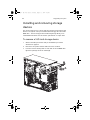
Installing and removing storage
devices
The system supports one 3.5-inch and three 5.25-inch internal storage
devices. The system comes pre-installed with a floppy drive and a CDROM drive. The two empty 5.25-inch half-height bays allow you to
install additional drives such as another optical drive or a tape drive.
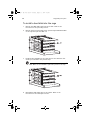
To remove a 5.25-inch storage device
1
Observe the ESD precautions and pre-installation procedures
described on page 37.
2
Disconnect the power and bus cables from the old drive.
3
Press the tool-less locking tabs on each side of the CD-ROM drive
(1) before pulling it from the chassis (2).
BB!H631!.!FO/cppl!!Qbhf!64!!Uvftebz-!Bvhvtu!28-!3115!!5;13!QN
53
To install a 5.25-inch storage device
Prior to inserting any device into a 5.25 inch device bay, you must
attach mounting rails to it.
Note : Contact you local Acer dealer or authorized service center
to purchase the 5.25 inch device mounting kit.
1
Attach the rails to the 5.25inch device with four screws (included in
the kit).
BB!H631!.!FO/cppl!!Qbhf!65!!Uvftebz-!Bvhvtu!28-!3115!!5;13!QN
54
3 Upgrading the system
2
Insert the CD-ROM drive into the drive bay until the locking tabs
click.
3
Connect the power and bus cables to the new drive.
4
Observe the post-installation instructions described on page 38.
BB!H631!.!FO/cppl!!Qbhf!66!!Uvftebz-!Bvhvtu!28-!3115!!5;13!QN
55
Upgrading the CPU
This section includes instructions for removing and installing a CPU.
To remove a CPU with heatsink
Before installing a new CPU in a socket, remove first any previously
installed CPU from that socket.
Important: Before removing a CPU from the mainboard, make
sure to create a backup file of all important data.
1
Observe the ESD precautions and pre-installation procedures
described on page 37.
2
Locate the CPU sockets on the mainboard.
3
To detach the CPU from its socket, follow the steps below:
Unplug the CPU fan from the mainboard (1).
Using a screwdriver, loosen the screws that hold the heatsink
assembly in place (2).
Remove the heatsink (3).
BB!H631!.!FO/cppl!!Qbhf!67!!Uvftebz-!Bvhvtu!28-!3115!!5;13!QN
56
3 Upgrading the system
Lift the CPU locking lever until it is fully extended (1).
Gently unseat and pull the CPU from the socket (2).
Warning! The heatsink becomes very hot when the system is on.
NEVER touch the heatsink with any metal or with your hands.
Processor Sequence
If only one CPU is to be installed, it must be installed in the CPU 1
socket, see “CPU socket 1” in “Mainboard layout” for more
information. In this case, the CPU 2 socket no longer requires a
termination module. When installing multiple processors, install CPU 1
first, then CPU 2.
To install a CPU with heatsink
1
Observe the ESD precautions and pre-installation procedures
described on page 37.
2
Locate the CPU socket on the mainboard.
3
Align the CPU to its socket, making sure that pin 1 (indicated by
the notched corner) of the CPU connects to hole 1 of the socket
(on the bottom right corner).
BB!H631!.!FO/cppl!!Qbhf!68!!Uvftebz-!Bvhvtu!28-!3115!!5;13!QN
57
4
To install the CPU to its socket, follow the steps below:
Insert the CPU into the socket (1).
Lower the CPU locking lever to secure the CPU (2).
BB!H631!.!FO/cppl!!Qbhf!69!!Uvftebz-!Bvhvtu!28-!3115!!5;13!QN
58
5
3 Upgrading the system
Replace the heatsink on top of the CPU (1).
Using a screwdriver, loosen the screws that hold the heatsink
assembly in place (2).
Plug the CPU fan in to the mainboard (3).
For help locating the CPU fan connectors on the mainboard, see
“Mainboard layout” on page 14.
6
Observe the post-installation instructions described on page 38.
BB!H631!.!FO/cppl!!Qbhf!6:!!Uvftebz-!Bvhvtu!28-!3115!!5;13!QN
59
Upgrading the system memory
This section includes instructions for removing and installing a
memory module.
The Server Boards Altos G520 each provides four DDR266 / DDR333
DIMM sites in two DIMM banks. The maximum memory capacity is 8GB
for either DDR266 or DDR333 memory. Memory DIMM technologies
supported are: 128MB, 256MB, 512MB, 1 GB and 2 GB.
The minimum memory configuration is one DIMM, installed in DIMM
socket 1B (the socket farthest from the processors). However, for
optimum performance and dual-channel interleave operation, a
minimum of two DIMMs should be installed. DIMMs on channel A are
paired with DIMMs on channel B to configure 2-way interleaving.
Both DIMMS in Bank 1 (DIMM1B and DIMM1A) must be populated
before any DIMMs are installed in Bank 2 (DIMM2B and DIMM2A).
Bank 2 must be populated in pairs.
Both DIMMs in a bank must be identical (same manufacturer, CAS
latency, number of rows, columns and devices, timing parameters etc.).
Although DIMMs within a bank must be identical, the BIOS supports
various DIMM sizes and configurations allowing the banks of memory
to be different.
Note: Dual-channel memory requires symmetrical memory
modules using the same density (e.g. 256MB,512MB), bus width
(e.g. x8 ,x16) and granule technology (e.g. 256M-bit, 512M-bit)
The mixing of DDR266 and DDR333 memory is supported on the Server
Boards Altos G520. However, when mixing DIMM types, DDR333 will
be treated as DDR266.
Warning! Functionality issues may be encountered if mixed
memory types are installed on the same server board. DIMM
modules of identical type, banking and stacking technology, and
vendor should be installed in the Altos G520.
BB!H631!.!FO/cppl!!Qbhf!71!!Uvftebz-!Bvhvtu!28-!3115!!5;13!QN
60
3 Upgrading the system
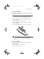
To remove a DIMM
Before installing a new DIMM in a socket, remove first any previously
installed DIMM from that socket.
Important: Before removing any DIMM from the mainboard,
make sure to create a backup file of all important data.
1
Observe the ESD precautions and pre-installation procedures
described on page 37.
2
Locate the DIMM slots on the mainboard.
3
Press the holding clips on both sides of the socket outward to
release the DIMM (1).
4
Gently pull the DIMM upward to remove it from the socket (2).
Note: Place your forefingers on the top of the DIMM before
pressing the holding clips to gently disengage the DIMM from the
socket.
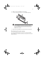
To install a DIMM
1
Observe the ESD precautions and pre-installation procedures
described on page 37.
2
Locate the DIMM slots on the mainboard.
3
Open the clips on the socket.
BB!H631!.!FO/cppl!!Qbhf!72!!Uvftebz-!Bvhvtu!28-!3115!!5;13!QN
61
4
Align then insert the DIMM into the socket (1).
5
Press the holding clips inward to lock the DIMM in place (2).
Note: The DIMM socket is slotted to ensure proper installation.
If you insert a DIMM but it does not fit easily into the socket, you
may have inserted it incorrectly. Reverse the orientation of the
DIMM and insert it again.
6
Observe the post-installation instructions described on page 38.
Reconfiguring the system memory
The system automatically detects the amount of memory installed.
Run the BIOS setup to view the new value for total system memory and
make a note of it.
BB!H631!.!FO/cppl!!Qbhf!73!!Uvftebz-!Bvhvtu!28-!3115!!5;13!QN
62
3 Upgrading the system
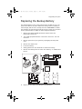
Replacing the Backup Battery
The lithium battery on the server board powers the RTC for up to 10
years in the absence of power. When the battery starts to weaken, it
loses voltage, and the server settings stored in CMOS RAM in the RTC
(for example, the date and time) may be wrong. Contact your customer
service representative or dealer for a list of approved devices.
1
Observe the safety and ESD precautions above and at the
beginning of this book.
2
Turn off all peripheral devices connected to the server. Turn off
the server.
3
Remove power from your system by unplugging the AC power
cord.
4
Remove the chassis cover.
5
Locate the battery.
6
Gently pull back on the metal tab to release the battery.
7
Remove the battery from its socket. See “Battery” in “Mainboard
layout”
8
Dispose of the battery according to local ordinance.
BB!H631!.!FO/cppl!!Qbhf!74!!Uvftebz-!Bvhvtu!28-!3115!!5;13!QN
63
9
Remove the new lithium battery from its package, and, being
careful to observe the correct polarity, insert it in the battery
socket.
10 Reconnect or replace any internal components you needed to
disconnect or remove.
11 Replace the server’s cover. Reconnect any external components
you needed to disconnect.
12 Attach the AC power cord.
13 Run Setup to restore the configuration settings to the RTC.
WARNING! Danger of explosion if battery is incorrectly replaced.
Replace only with the same or equivalent type recommended by
the equipment manufacturer. Discard used batteries according to
manufacturer’s instructions.
BB!H631!.!FO/cppl!!Qbhf!75!!Uvftebz-!Bvhvtu!28-!3115!!5;13!QN
64
3 Upgrading the system
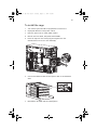
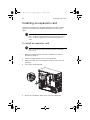
Installing an expansion card
This section explains how to install an expansion card. The onboard
expansion slots support PCI (Peripheral Component Interconnect)
cards.
Note : The BIOS setup automatically detects and assigns resources
to the new device (applicable only to Plug-and-Play expansion
cards).
To install an expansion card
Note: The illustrations used in this section show the Altos G520
server chassis.
1
Observe the ESD precautions and pre-installation procedures
described on page 37.
2
Locate an empty expansion slot on the mainboard.
3
With your finger, open the expansion card slot lock on the rear
panel (1).
4
Pull out the card bracket (2).
5
Remove the expansion card from its protective packaging.
BB!H631!.!FO/cppl!!Qbhf!76!!Uvftebz-!Bvhvtu!28-!3115!!5;13!QN
65
6
Align the card in an empty slot on the mainboard.
7
Insert the bracket with the card into the selected slot (1). Make
sure that the card is properly seated.
8
Secure the card by moving the expansion card locking lever back
to the locked position (2).
9
Observe the post-installation instructions described on page 38.
BB!H631!.!FO/cppl!!Qbhf!77!!Uvftebz-!Bvhvtu!28-!3115!!5;13!QN
66
3 Upgrading the system
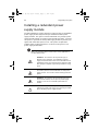
Installing a redundant power
supply module
The Altos G520 server power subsystem consists of two hot-swappable
power supply module bays that accept standard 610-watt power
supply modules. The system comes bundled with only a single power
supply module leaving one power supply module bay empty. You have
the option to purchase an extra power supply module to provide your
system with redundant power source. This power configuration
enables a fully-configured system to continue running even if one
power supply module fails.
Note: The redundant power source feature is only applicable to
the Altos G520 model.
WARNING! To reduce the risk of personal injury or
damage to the equipment, the installation of power
supply modules should be referred to individuals who are
qualified to service server systems and are trained to deal
with equipment capable of generating hazardous energy
levels.
WARNING! To reduce the risk of personal injury from
hot surfaces, observe the thermal labels on each power
supply module. You can also consider wearing protective
gloves.
WARNING! To reduce the risk of personal injury from
electric shock hazards, do not open the power supply
modules. There are no serviceable parts inside the
module.
Caution! Electrostatic discharge can damage electronic
components. Make sure that you are properly grounded
before handling a power supply module.
BB!H631!.!FO/cppl!!Qbhf!78!!Uvftebz-!Bvhvtu!28-!3115!!5;13!QN
67
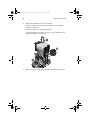
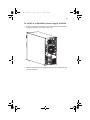
To install a redundant power supply module
1
Remove the screw securing the cover of the empty optional power
supply module bay, then remove the cover.
2
Slide the redundant power supply module into the empty bay until
you feel resistance.
BB!H631!.!FO/cppl!!Qbhf!79!!Uvftebz-!Bvhvtu!28-!3115!!5;13!QN
68
3 Upgrading the system
3
Press the module handle to secure the power supply module to the
bay.
4
Verify that the power indicators on both the main power supply
and on the newly installed redundant power supply are
illuminated (green).
BB!H631!.!FO/cppl!!Qbhf!7:!!Uvftebz-!Bvhvtu!28-!3115!!5;13!QN
4 BIOS
setup
BB!H631!.!FO/cppl!!Qbhf!81!!Uvftebz-!Bvhvtu!28-!3115!!5;13!QN
This chapter gives information about the
system BIOS and discusses how to configure
the system by changing the settings of the
BIOS parameters.
BB!H631!.!FO/cppl!!Qbhf!82!!Uvftebz-!Bvhvtu!28-!3115!!5;13!QN
71
BIOS setup
BIOS setup is a hardware configuration program built into your
system's Basic Input/Output System (BIOS). Since most systems are
already properly configured and optimized, there is no need to run this
utility. You will need to run this utility under the following conditions:
•
When changing the system configuration
•
When a configuration error is detected by the system and you are
prompted ("Run Setup" message) to make changes to the BIOS
setup
Note: If you repeatedly receive Run Setup messages, the battery
may be bad. In this case, the system cannot retain configuration
values in CMOS. Ask a qualified technician for assistance.
•
When redefining the communication ports to prevent any conflicts
•
When making changes to the Power Management configuration
•
When changing the password or making other changes to the
security setup
BIOS setup loads the configuration values in a battery-backed
nonvolatile memory called CMOS RAM. This memory area is not part
of the system RAM which allows configuration data to be retained
when power is turned off.
Before you run BIOS setup, make sure that you have saved all open
files. The system reboots immediately after you close the setup.
BB!H631!.!FO/cppl!!Qbhf!83!!Uvftebz-!Bvhvtu!28-!3115!!5;13!QN
72
4 BIOS setup
Entering BIOS setup
Power on the server to start the system POST (Power On Self Test)
process. During bootup, press <F2> to enter the BIOS setup screen.
Note: Note: You must press <F2> while the system is booting.
This hot key does not work at any other time.
There are several tabs on the setup screen corresponding to the six
major BIOS menus:
•
Main
•
Advanced
•
Boot
•
Security
•
Server
•
Exit
The parameters on the screens shown in this User’s guide display
default system values. These values may not be the same as those in
your system.
Note the following reminders when moving around the setup screen:
•
Use the Left and Right arrow keys to move to the next page or to
return to the previous screen.
•
Use the Up and Down arrow keys to select an item.
•
Use the + and - keys to select an option.
Note: You can configure a parameter that is enclosed in square
brackets. Grayed-out items have fixed settings and are not
user-configurable.
•
Use the Tab key to select a field.
•
Use the Enter key to display a submenu screen.
Note: When a parameter is preceded by a (>), it means that a
submenu screen is available.
BB!H631!.!FO/cppl!!Qbhf!84!!Uvftebz-!Bvhvtu!28-!3115!!5;13!QN
73
•
Press F1 for General Help on using the BIOS setup.
•
Press F10 to save changes and close the BIOS setup.
•
Press Esc to close the BIOS setup.
In the descriptive table following each of the screen illustrations,
settings in boldface are the default and suggested parameter settings.
BB!H631!.!FO/cppl!!Qbhf!85!!Uvftebz-!Bvhvtu!28-!3115!!5;13!QN
74
4 BIOS setup
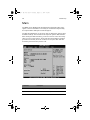
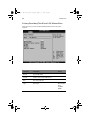
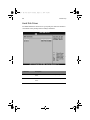
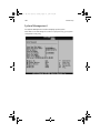
Main
The Main menu displays basic and important information about the
system. These information is necessary for troubleshooting and may
be required when asking for technical support.
The last two parameters on the screen lets you define the system’s time
and date settings. The real-time clock keeps the system date and time.
After setting the date and time, you do not need to enter them every
time you turn on the system. As long as the internal battery remains
good and connected, the clock continues to keep the date and time
accurately even when the power is off.
Parameter
Description
AMIBIOS Version
BIOS ID string (excluding build date)
Build Date
Date when the BIOS setup was created
BB!H631!.!FO/cppl!!Qbhf!86!!Uvftebz-!Bvhvtu!28-!3115!!5;13!QN
75
Parameter
Description
Processor Type
Processor brand ID string
Speed
Calculated processor speed
Count
Number of processors detected
System Memory Size
Amount of physical memory detected
System Time
Configures the system time in 24hour format
HH:MM:SS
System Date
Configures the system date.
Default value is Build Date
Language
Select the language used by BIOS. Choose from:
• English (default)
• French
• German
• Italian
• Spanish
BB!H631!.!FO/cppl!!Qbhf!87!!Uvftebz-!Bvhvtu!28-!3115!!5;13!QN
76
4 BIOS setup
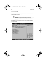
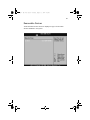
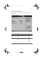
Advanced
The Advanced menu contains parameter values that define how the
system behaves on startup.
Warning! Be cautious in setting parameter values in the
Advanced menu as any incorrect value may cause the system to
malfunction.
Press Enter to enter the submenu screen of the parameters shown in
the screen below.
BB!H631!.!FO/cppl!!Qbhf!88!!Uvftebz-!Bvhvtu!28-!3115!!5;13!QN
77
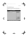
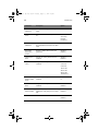
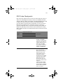
Processor Summary and Configuration
The Processor Summary/Configuration submenu displays general
information about the installed processor(s) and lets you define
advanced settings.
Parameter
Description
Options
Max CPUID
Value Limit
Enable to boot legacy operating systems
Disabled
HyperThreading Technology
Controls HyperThreading state. Used to
support older operating systems that do
not support HyperThreading.
Disabled
Enabled
Intel Speed
Step Tech
Disable for maximum CPU speed. Enable
to reduce CPU power consumption.
Auto
®
TM
Enabled
Disabled
BB!H631!.!FO/cppl!!Qbhf!89!!Uvftebz-!Bvhvtu!28-!3115!!5;13!QN
78
4 BIOS setup
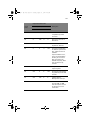
IDE Configuration
The IDE Configuration submenu lets you define the parameter settings
related to the hard disk/s.
Parameter
Description
Option
Onboard
P-ATA
Channels
Controls state of integrated P-ATA
controller.
Disabled
Primary
Secondary
Both
Onboard
S-ATA
Channels
Controls state of integrated S-ATA
controller.
Disabled
Enabled
Configure
S-ATA
as RAID
When enabled the S-ATA channels
are reserved to be used as RAID.
Disabled
Enabled
BB!H631!.!FO/cppl!!Qbhf!8:!!Uvftebz-!Bvhvtu!28-!3115!!5;13!QN
79
Parameter
Description
Option
S-ATA Ports
Definition
Defines priority between S-ATA
channels.
A1-3rdM / A2-4thM
Mixed P-ATA /
S-ATA
Lets you remove a P-ATA and
replace it by S-ATA in a given
channel. only one channel can be
S-ATA.
N/A
Primary IDE
Master
Selects submenu with additional
device deatils.
N/A
Primary IDE
Slave
Selects submenu with additional
device deatils.
N/A
Secondary IDE
Master
Selects submenu with additional
device deatils.
N/A
Secodary IDE
Slave
Selects submenu with additional
device deatils.
N/A
Third IDE
Master
Selects submenu with additional
device deatils.
N/A
Fourth IDE
Master
Selects submenu with additional
device deatils.
N/A
Hard Disk
Write Protect
Used to prevent unauthorized
writes to hard drives.
Disabled
IDE Detect
Time Out (sec)
Used with older IDE drives with
longer spin up times.
0
5
A1-4thM / A2-3rdM
Enabled
10
15
20
25
30
35
ATA(PI) 80Pin
Cable
Detection
80 pin cable is required for
UDMA-66 and above. BIOS detects
the cable by querying the host
and/or device.
Host & Device
Host
Device
BB!H631!.!FO/cppl!!Qbhf!91!!Uvftebz-!Bvhvtu!28-!3115!!5;13!QN
80
4 BIOS setup
Primary/Secondary/Third/Fourth IDE Master/Slave
These items let you select the IDE hard disk parameters that the system
supports.
Parameter
Description
Device
Type of IDE device
Vendor
Vendor of the selected IDE device
Size
Size of the IDE disk
Type
Driver type
Option
Not Installed
Auto
CD-ROM
ARMD
BB!H631!.!FO/cppl!!Qbhf!92!!Uvftebz-!Bvhvtu!28-!3115!!5;13!QN
81
Parameter
Description
Option
LBA/Large
Mode
Selects the hard disk drive translation
method. For drivers with more than 504
MB, the LBA mode is necessary.
Disabled
Block (MultiSector Transfer) Mode
Enhances disk performance depending on
the hard disk in use.
Disabled
Auto
PIO Mode
When set to Auto, BIOS setup
automatically detects if the installed hard
disk supports the function. If supported,
it allows for faster data recovery and
read/write timing that reduces hard disk
activity time. This results in better hard
disk performance.
Auto
Selects DMA (Direct Memory Access)
mode. Options include:
Auto: Auto detected
Auto
DMA Mode
Auto
If you set this parameter to Auto, BIOS
setup automatically detects if the
installed hard disk drive supports the
Block Mode function. If supported, it
allows data transfer in blocks (multiple
sectors) at a rate of 256 bytes per cycle.
If you set this parameter to Disabled, data
transfer from and to the device occurs
one sector at a time.
0
1
2
3
4
SWDMA0-0
SWDMAn: SingleWordDMAn
SWDMA0-1
SWDMA0-2
MWDMAn: MultiWordDMAn
MWDMA0-0
UDMAn: UltraDMAn
MWDMA0-1
MWDMA0-2
UWDMA0-0
UWDMA0-1
UWDMA0-2
UWDMA0-3
UWDMA0-4
UWDMA0-5
BB!H631!.!FO/cppl!!Qbhf!93!!Uvftebz-!Bvhvtu!28-!3115!!5;13!QN
82
4 BIOS setup
Parameter
Description
Option
S.M.A.R.T
Enables or disables the S.M.A.R.T (SelfMonitoring, Analysis and Reporting
Technology) function of the internal hard
disk.
Auto
Disabled
Enabled
If 'Auto' is selected, BIOS setup will enable the S.M.A.R.T function if the driver
supports it.
32-bit Data
Transfer
Enables or disables the 32-bit data
transfer function
Disabled
Enabled
BB!H631!.!FO/cppl!!Qbhf!94!!Uvftebz-!Bvhvtu!28-!3115!!5;13!QN
83
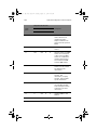
Floppy Configuration
The Floppy Configuration submenu displays the type of floppy drive
installed in the server.
Parameter
Description
Option
Floppy Drive A
Floppy disk drive type
None
720 KB, 3.5-inch
1.44 MB, 3.5-inch
2.88 MB, 3-5-inch
Onboard
Flopppy
Controller
Allows BIOS to enable or disable
the floppy controller.
Disabled
Enabled
BB!H631!.!FO/cppl!!Qbhf!95!!Uvftebz-!Bvhvtu!28-!3115!!5;13!QN
84
4 BIOS setup
Super I/O Configuration
The PCI/PnP Configuration submenu lets you specify the settings for
the PCI devices.
Parameter
Description
Option
Serial Port A
Address
Option that is used by other serial port is
hidden to prevent conflicting settings.
Disabled
3F8/IRQ4
2F8/IRQ3
3E8/IRQ4
2E8/IRQ3
Serial Port B
Address
Option that is used by other serial port is
hidden to prevent conflicting settings.
Disabled
3F8/IRQ4
2F8/IRQ3
3E8/IRQ4
2E8/IRQ3
BB!H631!.!FO/cppl!!Qbhf!96!!Uvftebz-!Bvhvtu!28-!3115!!5;13!QN
85
USB Configuration
The USB Configuration submenu lets you specify the settings for the
legacy devices and USB 2.0.
Parameter
Description
Option
USB Function
When set to disabled other USB options
are grayed out.
Disabled
Enables legacy USB support.
Disabled
Keyboard
only
Auto
Legacy USB
Support
Enabled
Keyboard
and
Mouse
BB!H631!.!FO/cppl!!Qbhf!97!!Uvftebz-!Bvhvtu!28-!3115!!5;13!QN
86
4 BIOS setup
Parameter
Description
Option
Port 60/64
Emulation
Should be enabled for full USB legacy
support.
Disabled
USB 2.0
Controller
Enables USB 2.0
Disabled
Enabled
USB 2.0
Controller
Mode
Set transfer rate at 480Mbps (Hi) or
12Mbps (full)
FullSpeed
Enabled
HiSpeed
BB!H631!.!FO/cppl!!Qbhf!98!!Uvftebz-!Bvhvtu!28-!3115!!5;13!QN
87
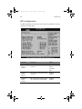
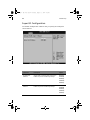
PCI Configuration
The PCI/PnP Configuration submenu lets you specify the settings for
the PCI devices.
Parameter
Description
Option
Onboard Video
Enables or disables VGA controller.
Disabled
Enabled
Dual Monitor
Video
Grayed out if onboard video is set to disabled.
Disabled
Enabled
Onboard NIC 1
(Left)
Enables or disables onboard Network
Interface Controller.
Disabled
Onboard NIC 1
ROM
Grayed out if device is disabled.
Disabled
Enabled
Enabled
BB!H631!.!FO/cppl!!Qbhf!99!!Uvftebz-!Bvhvtu!28-!3115!!5;13!QN
88
4 BIOS setup
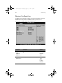
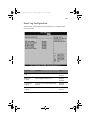
Memory Configuration
The Memory Configuration submenu provides information about the
DIMMs detected by BIOS. The DIMM number is printed on the
mainboard, see page 14 for help locating them.
Parameter
Description
Option
DIMM 1A
Non-User configurable informational display.
Installed
DIMM 1B
DIMM 2A
DIMM 2B
Extended
Memory Test
Not Installed
Disabled
Spare
Settings for testing extended memory.
1 MB
1 KB
Every
Location
Disabled
BB!H631!.!FO/cppl!!Qbhf!9:!!Uvftebz-!Bvhvtu!28-!3115!!5;13!QN
89
Parameter
Description
Option
Memory
Retest
When enabled, BIOS will activate and
retest all DIMMs on next boot. Automatically reset to disabled.
Disabled
Memory
Remap
Feature
Enable or disable remapping of overlapped PCI memory above physical memory.
Disabled
Enabled
Memory
Sparing
Grayed out if current memory configuration does not support sparing.
Disabled
Enabled
Spare
BB!H631!.!FO/cppl!!Qbhf!:1!!Uvftebz-!Bvhvtu!28-!3115!!5;13!QN
90
4 BIOS setup
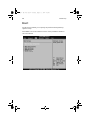
Boot
The Boot menu allows you to specify the preferred settings during
system bootup.
Press Enter to enter the submenu screen of the parameters shown in
the screen below.
BB!H631!.!FO/cppl!!Qbhf!:2!!Uvftebz-!Bvhvtu!28-!3115!!5;13!QN
91
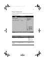
Boot Settings Configuration
The Boot Settings Configuration submenu lets you specify the
preferred settings for system bootup.
Parameter
Description
Option
Quick Boot
Allows the system to boot faster by
skipping some POST routines.
Disabled
Enables or disables the Quiet Boot function. When set to Enabled, BIOS setup is in
graphical mode and displays only an identification logo during POST and while
booting. After booting, the screen displays
the operating system prompt (such as DOS)
or logo (such as Windows). If any error
occurs while booting, the system
automatically switches to text mode.
Disabled
Enabled
Quiet Boot
Enabled
BB!H631!.!FO/cppl!!Qbhf!:3!!Uvftebz-!Bvhvtu!28-!3115!!5;13!QN
92
4 BIOS setup
Parameter
Description
Option
Bootup
Num-Lock
Sets the power on state for Numlock.
Off
PS/2 Mouse
Support
Enable this parameter if you intend to use
a mouse or trackball with a PS/2 interface.
On
Disabled
Enabled
Auto
POST Error
pause
When this item is enabled you will be
prompted when an error is detected during boot up. If disabled, the system will
boot with no intervention, if possible.
Disabled
Enabled
Hit ‘F2’ Message
Display
Displays “Press ‘F2’ to run Setup” during
POST.
Disabled
Enabled
Scan User Flash
Area
Allows BIOS to scan Flash ROM for user
binaries.
Disabled
Enabled
Boot Device Priority
The Boot Device Priority submenu lets you specify the boot search
sequence during the POST process.
BB!H631!.!FO/cppl!!Qbhf!:4!!Uvftebz-!Bvhvtu!28-!3115!!5;13!QN
93
BIOS setup will display an error message if the drive(s) specified is not
bootable.
Parameter
Description
1st Boot Device
Sets the device from which the system will first
attempt to boot up.
2nd thru 5th
Boot Device
Sets the device from which the system will attempt to
boot up when previoius attempts fail.
BB!H631!.!FO/cppl!!Qbhf!:5!!Uvftebz-!Bvhvtu!28-!3115!!5;13!QN
94
4 BIOS setup
Hard Disk Drives
The Hard Disk Drives submenu lets you specify the devices that will be
considered as the primary and secondary hard drives.
Parameter
Description
1st Drive
Sets the device to be considered the primary hard
drive.
2nd Drive
Sets the device to be considered the secondary hard
drive.
BB!H631!.!FO/cppl!!Qbhf!:6!!Uvftebz-!Bvhvtu!28-!3115!!5;13!QN
95
Removable Devices
The Removable Devices submenu displays the type of removable
devices available in the system.
BB!H631!.!FO/cppl!!Qbhf!:7!!Uvftebz-!Bvhvtu!28-!3115!!5;13!QN
96
4 BIOS setup
ATAPI CD/DVD Devices
The ATAPI (Advanced Technology Attachment Packet Interface)
CD-ROM submenu displays the type of ATAPI CD-ROM available in the
system.
BB!H631!.!FO/cppl!!Qbhf!:8!!Uvftebz-!Bvhvtu!28-!3115!!5;13!QN
97
Security
The Security menu allows you to safeguard and protect the system
from unauthorized use by setting up access passwords.
Parameter
Description
Option
Administrator
Password
Prevents unauthorized access to the
BIOS setup
Not Installed
Installed
User Password
Secures your system against unauthorized use. Once you set this password, you have to type it whenever
you boot the system. User password
is available only when a Supervisor
password is set.
Not Installed
Press Enter to change the Admin password.
N/A
Set Admin
Password
Installed
BB!H631!.!FO/cppl!!Qbhf!:9!!Uvftebz-!Bvhvtu!28-!3115!!5;13!QN
98
4 BIOS setup
Parameter
Description
Option
Set User
Password
Press Enter to change the User password.
N/A
User Access
Leves
Grayed out unless Admin password is
set.
No Access
View Only
Limited
Full Access
Clear User
Password
Grayed out unless Admin password is
set. Press Enter to clear the user password.
N/A
Fixed disk
boot sector
protect
Enable or disable boot sector virus
protection.
Disabled
Enabled
Password on
Boot
Grayed out if User password is not
installed.
Disabled
Secure Mode
Timer
Grayed out if User password is not
installed.
1 minute
Enabled
2 minutes
5 minutes
10 minutes
20 minutes
60 minutes
120 minutes
Secure Mode
HotKey (CTRLALT-)
Grayed out if User password is not
installed.
L
Secure Mode
Boot
Grayed out if User password is not
installed.
Disabled
Front Panel
Switch Inhibit
Grayed out if a password is not
installed or if AC policy is set to Stays
Off.
Disabled
NMI Control
Enable or disable NMI control.
Disabled
Enabled
Z
Enabled
Enabled
BB!H631!.!FO/cppl!!Qbhf!::!!Uvftebz-!Bvhvtu!28-!3115!!5;13!QN
99
To set an Administrator/User password
1
Use the up/down keys to highlight a password parameter
(Administrator Password or User Password) then press Enter.
A password box will appear.
2
Type a password then press Enter.
The password may consist of up to six alphanumeric characters
(A-Z, a-z, 0-9).
3
Retype the password to verify the first entry then press Enter
again.
After setting the password, the system automatically sets the
chosen password parameter to Installed.
To remove the User password
1
Use the up/down keys to highlight the Clear User Password
parameter then press Enter.
2
Enter the current Admin password then press Enter.
3
Press Enter twice without entering anything in the new and
confirm password fields.
After doing this, the system automatically sets the User password
parameter to Not Installed.
BB!H631!.!FO/cppl!!Qbhf!211!!Uvftebz-!Bvhvtu!28-!3115!!5;13!QN
100
4 BIOS setup
Server
The Server menu allows you to configure the system parameters .
Parameter
Description
Option
System
Management
Press Enter to enter the submenu screen.
N/A
Serial Console
Features
Press Enter to enter the submenu screen.
N/A
Event Log
configuration
Press Enter to enter the submenu screen.
N/A
Assert NMI on
SERR
If enabled, NMI generated on SERR and
logged.
Disabled
Assert NMI on
PERR
Grayed out in NMI on SERR is disabled.
Disabled
Enabled
Enabled
BB!H631!.!FO/cppl!!Qbhf!212!!Uvftebz-!Bvhvtu!28-!3115!!5;13!QN
101
Parameter
Description
Option
Resume on AC
Power Loss
When set to Stays Off, Front Panel Switch
Inhibit (in BIOS Security menu) is disabled.
Stays Off
FRB-2 Policy
Controls action if boot processor is disabled or not.
Retry on
Next Boot
Power On
Disable
FRB2 Timer
Late POST
Timeout
Controls time limit for add-in card detection.
Disabled
5 minutes
10 minutes
15 minutes
20 minutes
Hard Disk OS
Boot Timeout
Controls the time limit for booting an OS
from a HDD.
Disabled
5 minutes
10 minutes
15 minutes
20 minutes
PXE OS Boot
Timeout
Controls the time limit for booting an OS
using PXE boot.
Disabled
5 minutes
10 minutes
15 minutes
20 minutes
OS Watchdog
Timer Policy
Controls the policy upon timeout.
Stay On
Reset
Power Off
Platform Event
Filtering
Enable or disable trigger for system sensor
events.
Disabled
Enabled
BB!H631!.!FO/cppl!!Qbhf!213!!Uvftebz-!Bvhvtu!28-!3115!!5;13!QN
102
4 BIOS setup
System Management
The System Management submenu displays specific system
information. The following is for reference purposes only, your system
configuration may vary.
BB!H631!.!FO/cppl!!Qbhf!214!!Uvftebz-!Bvhvtu!28-!3115!!5;13!QN
103
Serial Console Features
The Serial Console Features submenu allows you to configure serial
port settings.
Parameter
Description
Option
BIOS
Redirection
Port
If enabled, BIOS uses the specified serial
port to redirect the console to a remote
terminal.
Disabled
Serial A
Baud Rate
Sets the transfer speed for console redirection.
9600
Serial B
19.2 K
38.4 K
57. 6 K
115.2 K
BB!H631!.!FO/cppl!!Qbhf!215!!Uvftebz-!Bvhvtu!28-!3115!!5;13!QN
104
4 BIOS setup
Parameter
Description
Option
Flow Control
If enabled, the system uses the flow control selected.
No Flow
Control
CTS/RTS
XON/XOFF
CTS/RTS+CD
Terminal Type
PC-ANSI
VT100+
VT-UTF8
ACPI Redirection port
Enable or disable ACPI OS Headless Console Redirection.
Disabled
Serial A
Serial B
BB!H631!.!FO/cppl!!Qbhf!216!!Uvftebz-!Bvhvtu!28-!3115!!5;13!QN
105
Event Log Configuration
The Event log configuration submenu allows you to configured the
event log setting.
Parameter
Description
Option
Clear All Event
Logs
Enable to clear logs.
Disabled
Enabled
BIOS Event
Logging
Allows logging of BIOS events.
Critical Event
Logging
Logs fatal errors including PERR, SERR,
and ECC.
ECC Event
Logging
Enable or disable ECC event logging.
Disabled
Enabled
Disabled
Enabled
Disabled
Enabled
BB!H631!.!FO/cppl!!Qbhf!217!!Uvftebz-!Bvhvtu!28-!3115!!5;13!QN
106
4 BIOS setup
Parameter
Description
Option
PCI Error
Logging
Enable or disable PCI error logging.
FSB Error
Logging
Enable or disable Front-Side Bus logging.
Disabled
Enabled
Hublink Error
Logging
Enable or disable Hublink error logging.
Disabled
Disabled
Enabled
Enabled
BB!H631!.!FO/cppl!!Qbhf!218!!Uvftebz-!Bvhvtu!28-!3115!!5;13!QN
107
Exit
The Exit menu displays the various options to quit from the BIOS setup.
Highlight any of the exit options then press Enter.
Parameter
Description
Save Changes
and Exit
Saves changes made and close the BIOS setup.
Pressing F10 can also be used.
Discard
Changes and
Exit
Exit system setup without saving changes.
Discard
Changes
Discard any changes made to setup without exiting.
Pressing F7 can also be used.
Load Setup
Defaults
Loads the original BIOS setup parameters.
Pressing Esc can also be used.
Pressing F9 can also be used.
BB!H631!.!FO/cppl!!Qbhf!219!!Uvftebz-!Bvhvtu!28-!3115!!5;13!QN
108
4 BIOS setup
Parameter
Description
Load Custom
Defaults
Loads the custom settings for all BIOS parameters as
saved by user.
Save Custom
Defaults
Saves custom settings for all BIOS parameters.
BB!H631!.!FO/cppl!!Qbhf!21:!!Uvftebz-!Bvhvtu!28-!3115!!5;13!QN
109
Upgrading the BIOS
The upgrade utility allows you to upgrade the BIOS in flash memory.
The code and data in the upgrade file include the following:
•
On-board BIOS, ATA-100 RAID BIOS, and PXE option ROMs for the
devices that are embedded on the system board
•
The Setup Utility
•
The System BIOS
Preparing for the Upgrade
The steps below explain how to prepare to upgrade the BIOS,
including how to:
•
Record the current BIOS settings
•
Obtain the upgrade utility
•
Prepare a bootable diskette for the utility
In the unlikely event that a BIOS error occurs during the BIOS update
process, see "Recovering the BIOS" for instructions on performing a
BIOS recovery.
Recording the Current BIOS Settings
1
Boot the computer and press <F2> when you see the message:
Press <F2> Key if you want to run SETUP
2
Write down the current settings in the BIOS Setup program.
Note: Do not skip step 2. You will need these settings to
configure your computer at the end of the procedure.
Obtaining the Upgrade
Download the BIOS image file to a temporary folder on your hard
drive.
BB!H631!.!FO/cppl!!Qbhf!221!!Uvftebz-!Bvhvtu!28-!3115!!5;13!QN
110
4 BIOS setup
Note: Review the instructions distributed with the upgrade
utility before attempting a BIOS upgrade. Review also any release
notes in the release notes file that accompanies the new version
of the BIOS. The release notes may contain critical information
regarding jumper settings, specific fixes, or other information to
complete the upgrade.
Creating a Bootable Diskette
Use a DOS system to create the diskette as follows:
1
Insert a diskette in diskette drive A.
2
At the C:\ prompt, for an unformatted diskette, type:
format a:/s
3
or, for a diskette that is already formatted, type:
sys a:
4
Press <Enter>.
Creating the BIOS Upgrade Diskette
The BIOS upgrade file is a compressed self-extracting archive that
contains the files you need to upgrade the BIOS.
1
Insert the bootable diskette into the diskette drive.
2
While in the directory into which you downloaded the upgrade
file(s), type [filename] a: where “[filename]” is the name of the file
that you downloaded. This command extracts the update files and
places them onto the bootable diskette
Upgrading the BIOS
1
Place the bootable diskette containing the BIOS update files into
the diskette drive of your system. Boot the system with the
diskette in the drive.
2
A menu will appear with two options. Use option 1 to
automatically update the system BIOS.
Use option 2 to manually update the system BIOS and the User
Binary.
BB!H631!.!FO/cppl!!Qbhf!222!!Uvftebz-!Bvhvtu!28-!3115!!5;13!QN
111
3
If you selected option 1, to automatically update the system BIOS:
The system will execute the AfuDOS update utility to update the
BIOS. When the update is complete, the utility will display a green
box with a message that says “Completed Successfully.” The
system will then reboot.
4
4.If you selected option 2, to manually update the BIOS or to
update the flash memory, you can either select “Update Flash
Memory From a File” or “Update System BIOS”:
•
Update Flash Memory From a File: When prompted for a file
name, type BIOS.wph and press Enter.
•
Update System BIOS: The system will warn you that the BIOS
will be updated. Verify the BIOS version is correct and press
Enter to continue. When the update is complete, the utility
will display a green box with a message that says “Completed
Successfully.” The system will then reboot.
5
Wait while the BIOS files are updated. Do not power down the
system during the BIOS update process! The system will reset
automatically when the BIOS update process is completed. Remove
the diskette from the diskette drive.
6
Check to make sure the BIOS version displayed during POST is the
new version as the system reboots.
7
Enter Setup by pressing the F2 key during boot.
8
In Setup, press the F9 and <Enter> to set the parameters back to
default values.
9
Re-enter the values you wrote down at the beginning of this
process. Press F10 and <Enter> to exit BIOS Setup and Save
Changes.
10 If you do not set the CMOS values back to defaults using the F9
key, the system may function erratically.
Note: You may encounter a CMOS Checksum error or other
problem after reboot. If this happens, shut down the system and
boot it again. CMOS checksum errors require that you enter Setup,
check your settings, save your settings, and exit Setup.
BB!H631!.!FO/cppl!!Qbhf!223!!Uvftebz-!Bvhvtu!28-!3115!!5;13!QN
112
4 BIOS setup
Changing the BIOS Language
You can use the BIOS upgrade utility to change the language the BIOS
uses for messages and the Setup program. Use a bootable diskette
containing the Acer flash utility and language files.
1
Boot the computer with the bootable diskette in drive A. The BIOS
upgrade utility screen appears.
2
Select Update Flash Memory From a File.
3
Select Update Language Set. Press <Enter>.
4
Select drive A and use the arrow keys to select the correct .lng file.
Press <Enter>.
5
When the utility asks for confirmation that you want to flash the
new language into memory, select continue with Programming.
Press <Enter>.
6
When the utility displays the message upgrade is complete,
remove the diskette. Press <Enter>.
7
The computer will reboot and the changes will take effect.
Recovering the BIOS
In the rare event that the BIOS becomes damaged, a recovery process
needs to be followed to return the system to service. Two methods are
available to recover the BIOS: automatically with the crisis recovery
diskette, and manually by moving a jumper on the system board. These
methods are described below.
Note: BIOS recovery is the mode of last resort, used only when
the main system BIOS will not come up.
Manually Recovering the BIOS
A BIOS recovery can be manually initiated. This option would be used
only when the BIOS is corrupt, but the ROM checksum error does not
occur during POST. To manually initiate a BIOS recovery, use the
following steps:
1
Power down and uplug the system from the AC power source.
BB!H631!.!FO/cppl!!Qbhf!224!!Uvftebz-!Bvhvtu!28-!3115!!5;13!QN
113
2
Move the recovery jumper at J1D1 from pins 13 and 14 to cover
pins 14 and 15.
3
Insert a bootable diskette containing the file AMIBOOT.ROM into
the A: diskette drive.
4
Plug the system into the AC power source and power it on.
5
A blue screen will be displayed and the recovery process will
automatically run. The system will continue to beep throughout
the recovery process. The recovery process is complete when the
beeping stops.
6
Remove the diskette.
7
Power down and unplug the system from the AC power source.
8
Move the BIOS recovery jumper at J1D1 back to the original
position, covering pins 13 and 14.
9
Plug the system into the AC power source and power it up to
confirm that the recovery was successful.
Clearing the CMOS
If you are not able to access the BIOS setup screens, the CMOS Clear
jumper will need to be used to reset the configuration RAM. The
CMOS Clear jumper is located on jumper block J17.
1
Power down the system and disconnect the AC power.
2
Open the server.
3
Move the jumper from pins 1 and 2 to the Clear CMOS position,
covering pins 2 and 3.
4
Reconnect the AC power, power up the system.
5
When the system begins beeping, power it down and disconnect
the AC power.
6
Return the CMOS Clear jumper to the original location, covering
pins 1 and 2.
7
Close the server chassis, reconnect the AC power and power up the
system.
BB!H631!.!FO/cppl!!Qbhf!225!!Uvftebz-!Bvhvtu!28-!3115!!5;13!QN
114
4 BIOS setup
Clearing the Password
If the user or administrator password(s) is lost or forgotten, moving the
password clear jumper into the “clear” position clears both passwords.
The password clear jumper must be restored to its original position
before a new password(s) can be set. The password clear jumper is
located on jumper block J17.
1
Power down the system and disconnect the AC power.
2
Open the server chassis.
3
Move the jumper from pins 5 and 6 to the Clear Password position,
covering pins 6 and 7.
4
Reconnect the AC power, power up the system.
5
Power down the system and disconnect the AC power.
6
Return the Password Clear jumper to the original location,
covering pins 5 and 6.
7
Close the server chassis.
BB!H631!.!FO/cppl!!Qbhf!226!!Uvftebz-!Bvhvtu!28-!3115!!5;13!QN
115
BIOS Error Messages
When a recoverable error occurs during the POST, the BIOS displays an
error message describing the problem.
Error Message
Explanation
GA20 Error
An error occurred with Gate A20 when switching to
protected mode during the memory test.
Pri Master HDD Error
Pri Slave HDD Error
Sec Master HDD Error
Sec Slave HDD Error
Could not read sector from corresponding drive.
Pri Master Drive ATAPI Incompatible
Pri Slave Drive ATAPI Incompatible
Sec Master Drive ATAPI Incompatible
Sec Slave Drive ATAPI Incompatible
Corresponding drive is not an ATAPI device. Run
Setup to make sure device is selected correctly.
A: Drive Error
No response from diskette drive.
CMOS Battery Low
The battery may be losing power. Replace the battery soon.
CMOS Display Type
Wrong
The display type is different than what has been
stored in CMOS. Check Setup to make sure type is
correct.
CMOS Checksum Bad
The CMOS checksum is incorrect. CMOS memory
may have been corrupted. Run Setup to reset values.
CMOS Settings
Wrong
CMOS values are not the same as the last boot.
These values have either been corrupted or the battery has failed.
CMOS Date/Time Not
Set
The time and/or date values stored in CMOS are
invalid. Run Setup to set correct values.
DMA Error
Error during read/write test of DMA controller.
BB!H631!.!FO/cppl!!Qbhf!227!!Uvftebz-!Bvhvtu!28-!3115!!5;13!QN
116
4 BIOS setup
Error Message
Explanation
FDC Failure
Error occurred trying to access diskette drive controller.
HDC Failure
Error occurred trying to access hard disk controller.
Checking NVRAM.....
NVRAM is being checked to see if it is valid.
Update OK!
NVRAM was invalid and has been updated.
Updated Failed
NVRAM was invalid but was unable to be updated.
Keyboard Error
Error in the keyboard connection. Make sure keyboard is connected properly.
KB/Interface Error
Keyboard interface test failed.
Memory Size
Decreased
Memory size has decreased since the last boot. If no
memory was removed, then memory may be bad.
Memory Size
Increased
Memory size has increased since the last boot. If no
memory was added, there may be a problem with
the system.
Memory Size
Changed
Memory size has changed since the last boot. If no
memory was added or removed, then memory may
be bad.
No Boot Device
Available
System did not find a device to boot.
Off Board Parity
Error
A parity error occurred on an off-board card. This
error is followed by an address.
On Board Parity Error
A parity error occurred in onboard memory. This
error is followed by an address.
Parity Error
A parity error occurred in onboard memory at an
unknown address.
NVRAM / CMOS /
PASSWORD cleared
by Jumper
NVRAM, CMOS, and passwords have been cleared.
The system should be powered down and the
jumper removed.
<CTRL_N> Pressed
CMOS is ignored and NVRAM is cleared. User must
enter Setup.
BB!H631!.!FO/cppl!!Qbhf!228!!Uvftebz-!Bvhvtu!28-!3115!!5;13!QN
117
BIOS POST Beep Codes
The table below lists the POST error beep codes. Prior to system video
initialization, the BIOS uses these beep codes to inform users of error
conditions. The beep code occurs only when a critical error occurs or
when the BIOS fails to boot to the operating system. Please note that
not all error conditions are supported by BIOS beep codes.
Number of Beeps
Description
1
Refresh failure
2
Parity cannot be reset
3
First 64 Kb memory failure
4
Timer not operational
5
Processor failure (Reserved; not used)
6
8042 GateA20 cannot be toggled (memory failure or
not present)
7
Exception interrupt error
8
Display memory R/W error
9
(Reserved; not used)
10
CMOS Shutdown register test error
11
Invalid BIOS (such as, POST module not found)
BB!H631!.!FO/cppl!!Qbhf!229!!Uvftebz-!Bvhvtu!28-!3115!!5;13!QN
118
4 BIOS setup
BIOS Recovery Beep Codes
Beeps
Reason
1
One long beep - video is active.
1-2
One long beep and two short beeps: Insert the BIOS recovery
diskette.
An error or warning condition at boot can result in a series of beeps
being issued known as "beep codes.” These beeps have a code that
identifies system or PCI card events. For example, some Acer RAID cards
have beep codes. Before checking for a system beep code error make
sure the PCI card is not causing the beeping.
BB!H631!.!FO/cppl!!Qbhf!22:!!Uvftebz-!Bvhvtu!28-!3115!!5;13!QN
119
Configuration and BIOS Select
Jumpers
CMOS CLEAR
BMC Control
2
Force Erase
3
J17 (1x11)
4
A
PASSWORD CLEAR
5
Protect
6
Erase
7
8
RECOVERY BOOT
9
Normal Boot
10
Recovery Boot
11
B
J29 BIOS SEL
1-2 Normal Boot
(off of either bank)
2
3
2-3 Force Boot
(off of bank 0 BIOS)
2
3
Configuration Jumper [J17]
Jumper Name
Pins
What happens at system reset...
CMOS clear
2-3
If these pins are jumpered, the CMOS
settings will be cleared on the next reset.
These pins should be jumpered on 1-2 for
normal operation.
BB!H631!.!FO/cppl!!Qbhf!231!!Uvftebz-!Bvhvtu!28-!3115!!5;13!QN
120
4 BIOS setup
Jumper Name
Pins
What happens at system reset...
Password Clear
6-7
If these pins are jumpered, administrator
and user passwords will be cleared on the
next reset. These pins should be
jumpered on 5-6 for normal operation.
BIOS Recovery
10-11
If these pins are jumpered, the system
will attempt to recover the BIOS by
loading the BIOS code into the flash
device from a floppy disk. This jumper is
typically only used when the BIOS has
become corrupted. These pins should be
jumpered on 9-10 for normal operation.
BIOS Select Jumper [J29]
Operation
Pins
What happens at system reset...
Normal Boot
1-2
If these pins are jumpered, the board will
boot off of either BIOS (bank.0 or bank 1)
depending on which is available first.
Force Boot
2-3
If these pins are jumpered, the board will
boot off of bank 0 BIOS.
BB!H631!.!FO/cppl!!Qbhf!232!!Uvftebz-!Bvhvtu!28-!3115!!5;13!QN
Appendix A:
Troubleshooting
BB!H631!.!FO/cppl!!Qbhf!233!!Uvftebz-!Bvhvtu!28-!3115!!5;13!QN
This chapter helps you identify and solve
problems that might occur while you are
using the system.
BB!H631!.!FO/cppl!!Qbhf!234!!Uvftebz-!Bvhvtu!28-!3115!!5;13!QN
123
For any problem that you are encountering, first ensure you are using
the latest firmware and files. Firmware upgrades include updates for
BIOS and the hot-swap controller (HSC). In addition to the server
firmware and files, also update any drivers used for components you
have installed in your system, such as video drivers, network drivers,
and SCSI drivers.
Acer provides a package called the “Platform Confidence Test” that
may help with your diagnostics.
Resetting the System
Before going through in-depth troubleshooting, attempt first to
perform reset your system using one of the methods below.
To do this:
Press
Soft boot reset to clear the system memory and reload the
operating system.
<Ctrl+Alt+Del>
Clear system memory, restart POST, and reload the
operating system.
Reset button
Cold boot reset. Turn the system power off and then on.
This clears system memory, restarts POST, reloads the
operating system, and halts power to all peripherals.
Power off/on
Problems following Initial System Installation
Problems that occur at initial system startup are usually caused by an
incorrect installation or configuration. Hardware failure is a less
frequent cause. If the problem you are experiencing is with a specific
software application, see "Problems with Newly Installed Application
Software".
First Steps Checklist
•
AC power available at the wall outlet?
•
Are the power supplies plugged in? Check the AC cable(s) on the
back of the chassis and at the AC source.
•
Are all cables correctly connected and secured?
BB!H631!.!FO/cppl!!Qbhf!235!!Uvftebz-!Bvhvtu!28-!3115!!5;13!QN
124
Appendix A: Troubleshooting
•
Are the processors fully seated in their sockets on the server
board?
•
Are all standoffs in the proper location and not touching any
components, causing a potential short?
•
Are all add-in PCI boards fully seated in their slots on the server
board?
•
Are all jumper settings on the server board correct?
•
Are all jumper and switch settings on add-in boards and peripheral
devices correct? To check these settings, refer to the
manufacturer’s documentation that comes with them. If
applicable, ensure that there are no conflicts - for example, two
add-in boards sharing the same interrupt.
•
Are all peripheral devices installed correctly?
•
If the system has a hard disk drive, is it properly formatted or
configured?
•
Are all device drivers properly installed?
•
Are the configuration settings made in Setup correct?
•
Is the operating system properly loaded? Refer to the operating
system documentation.
•
Did you press the system power on/off switch on the control panel
to turn the server on (power on light should be lit)?
•
Is the system power cord properly connected to the system and
plugged into a NEMA 5-15R outlet for 100-120 V~ or a NEMA 615R outlet for 200-240 V~?
•
Are all integrated components from the tested components lists?
Check the tested memory, and chassis lists, as well as the
supported hardware and operating system list.
Hardware Diagnostic Testing
This section provides a more detailed approach to identifying a
hardware problem and locating its source.
CAUTION : Turn off devices before disconnecting cables: Before
disconnecting any peripheral cables from the system, turn off the
system and any external peripheral devices. Failure to do so can
cause permanent damage to the system and/or the peripheral
devices.
BB!H631!.!FO/cppl!!Qbhf!236!!Uvftebz-!Bvhvtu!28-!3115!!5;13!QN
125
1
Turn off the system and all external peripheral devices. Disconnect
each of device from the system, except for the keyboard and the
video monitor.
2
Make sure the system power cord is plugged into a properly
grounded AC outlet.
3
Make sure your video display monitor and keyboard are correctly
connected to the system. Turn on the video monitor. Set its
brightness and contrast controls to at least two thirds of their
maximum ranges (see the documentation supplied with your video
display monitor).
4
If the operating system normally loads from the hard disk drive,
make sure there is no diskette in drive A and no CD-ROM disk in
the CD-ROM drive.
5
If the power LED does light, attempt to boot from a floppy
diskette or from a CD-ROM disk.
6
Turn on the system. If the power LED does not light, see "Power
Light Does Not Light".
Verifying Proper Operation of Key System
Lights
As POST determines the system configuration, it tests for the presence
of each mass storage device installed in the system. As each device is
checked, its activity light should turn on briefly. Check for the
following:
Does the diskette drive activity light turn on briefly? If not, see
"Diskette Drive Activity Light Does Not Light".
If system LEDs are illuminated, see "LED Information" for a description
of the light and steps to take to correct the problem.
Confirming Loading of the Operating System
Once the system boots up, the operating system prompt appears on
the screen. The prompt varies according to the operating system. If
the operating system prompt does not appear, see "No Characters
Appear on Screen".
BB!H631!.!FO/cppl!!Qbhf!237!!Uvftebz-!Bvhvtu!28-!3115!!5;13!QN
126
Appendix A: Troubleshooting
Specific Problems and Corrective Actions
This section provides possible solutions for these specific problems:
•
Power light does not light.
•
No characters appear on screen.
•
Characters on the screen appear distorted or incorrect.
•
System cooling fans do not rotate.
•
Diskette drive activity light does not light.
•
Hard disk drive activity light does not light.
•
CD-ROM drive activity light does not light.
•
There are problems with application software.
•
The bootable CD-ROM is not detected.
Try the solutions below in the order given. If you cannot correct the
problem, contact your service representative or authorized dealer for
help.
Power Light Does Not Light
Check the following:
•
Did you press the power-on button?
•
Is the system operating normally? If so, the power LED might be
defective or the cable from the control panel to the server board
might be loose.
•
Have you securely plugged the server AC power cord into the
power supply?
•
Is the power supply correctly set to 110V or 235V, depending on
your power output?
•
Will other items plugged into the same power outlet function
correctly?
•
Some ATX power supplies have a power switch on the back of the
power supply, next to the fan. If your system has one, is it turned
on?
•
Remove all add-in cares and see if the system boots. If successful,
add the cards back in one at a time with a reboot between each
addition.
•
Make sure the memory DIMMs comply with the system
BB!H631!.!FO/cppl!!Qbhf!238!!Uvftebz-!Bvhvtu!28-!3115!!5;13!QN
127
requirements.
•
Make sure the memory DIMMs have been populated according to
the system requirements.
•
Remove the memory DIMMs and re-seat them.
•
Make sure the processor(s) comply with the system requirements.
•
Make sure the processor(s) have been populated according to the
system requirements.
•
Remove the processor(s) and re-seat them.
Make sure the chassis standoffs are installed only below mounting
holes. Misplaced standoffs can contact the pins on the bottom of the
server board and cause a short.
No Characters Appear on Screen
Check the following:
•
Is the keyboard functioning? Test it by turning the “Num Lock”
function on and off to make sure the Num Lock light is
functioning.
•
Is the video monitor plugged in and turned on? If you are using a
switch box, is it switched to the correct system?
•
Are the brightness and contrast controls on the video monitor
properly adjusted?
•
Is the video monitor signal cable properly installed?
•
Does this video monitor work correctly if plugged into a different
system?
•
Is the onboard video controller enabled in the BIOS?
•
Remove all add-in cares and see if the video returns. If successful,
add the cards back in one at a time with a reboot between each
addition.
•
Make sure the memory DIMMs comply with the system
requirements.
•
Make sure the memory DIMMs have been populated according to
the system requirements.
•
Remove the memory DIMMs and re-seat them.
•
Make sure the processor(s) comply with the system requirements.
•
Make sure the processor(s) have been populated according to the
BB!H631!.!FO/cppl!!Qbhf!239!!Uvftebz-!Bvhvtu!28-!3115!!5;13!QN
128
Appendix A: Troubleshooting
system requirements.
•
Remove the processor(s) and re-seat them