1
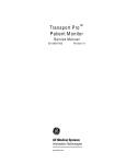
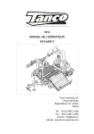
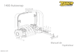
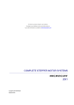
ILLUSTRATED PARTS MANUALS
T300 THERMAL BINDER
220-240V
T300
THERMAL BINDER
220-240V
ILLUSTRATED PARTS LISTS
AND
SERVICE INSTRUCTIONS
Compiled by
Approved by
Issue No 2
(Technical Manager)
Date
REXEL BUSINESS MACHINES, DROITWICH, WORCESTERSHIRE, WR9 9AP, ENGLAND
TELEPHONE +44 (0) 1905 771555 FAX +44 (0) 1905 823374
T300.doc
Issue No 1
1
ILLUSTRATED PARTS MANUALS
T300 THERMAL BINDER
220-240V
TABLE OF CONTENTS
ILLUSTRATED PARTS MANUAL
T300 THERMAL BINDER
220-240V
Contents
Page 2
Preface
Page 3
Illustrated parts list - Mouldings
Mechanism and Electrics
Pages 4 – 5
Pages 6 – 8
Service Instructions - To serial No A545817
Pages 9 – 14
Section 1.0 Replacement of Top Cover
Section 2.0 Replace lid moulding
Section 2.1 Replacement of Heater Assembly
Section 2.2 Replacement of Fixing Blocks
Section 2.3 Replacement of Insulation
Section 2.4 Replacement of base moulding
Section 3.0 Replacement of PCB
Section 4.0 Replacement of document support bar/
Spring/Lever arm
Section 4.1 Replacement of buttons
Section 4.2 Replacement of Thermistor
Section 5.0 Wiring Diagram 220/240
To Serial No A545817
Page 9
Page 10
Page 10
Page 11
Page 11
Page 11
Page 12
Page 12
Page 12
Page 13
Page 14
Service Instructions - From Serial No A545818
Section 6.0 Replacement of Top Cover
Section 7.0 Replace lid moulding
Section 7.1 Replacement of Heater Assembly
Section 7.2 Replacement of Fixing Blocks
Section 7.3 Replacement of Insulation
Section 7.4 Replacement of base moulding
Section 8.0 Replacement of PCB
Section 9.0 Replacement of document support bar/
Spring/Lever arm
Section 9.1 Replacement of buttons
Section 10.0 Wiring Diagram 220/240
From Serial No A545818
Page 15
Page 16
Page 16
Page 17
Page 17
Page 17
Page 17
Section 11 Specifications
Amendment Record Sheet
Page 20
Page 21
T300.doc
Issue No 1
2
Page 18
Page 18
Page 19
ILLUSTRATED PARTS MANUALS
T300 THERMAL BINDER
220-240V
PREFACE
SERVICE PREPARATION
This manual provides the instructions for the replacement of all the components that may become worn or
damaged. Details of replacement parts and ordering information are given in associated illustrated parts list.
Illustrated Parts Lists
For each machine give full details of the replacement part numbers with
supporting diagrams to show the location of the components.
Service Instructions
For each machine give the recommended servicing procedure with supporting
pictorial diagrams for added clarity.
WARNING
1.
Check the machine RATING PLATE DETAILS are compatible with the electrical mains supply.
2.
Disconnect the electrical mains supply before removing any covers.
3.
Upto serial number A545817, all machines must have a sound electrical earth connection.
From serial number A545818 all machines are double insulated and do not require an earth
connection.
T300.doc
Issue No 1
3
ILLUSTRATED PARTS MANUALS
T300 THERMAL BINDER
220-240V
MOULDINGS
No
1
2
3
4
5
6
7
8
9
10
11
12
13
Description
Service Call Decal
Bottom Moulding
On Button – Grey
Off Button – Red
Programme Select Button – Yellow
Bind Button – Green
Lid Pad Print
Top Cover Pad Print
No 4 x ½” Pan Plasfast Screw
Self Adhesive Rubber Feet
Document Feet
Spring Arm
Coil Spring
T300.doc
Issue No 1
Part
D000185
D52501
D52507
D52508
D52509
D52510
D52516
D52517
SCR716
SL18-294
D52519
D52512
D52518
4
Qty
1
1
1
1
1
1
1
1
6
4
1
1
1
Comment
Not shown
Not shown
Not shown
ILLUSTRATED PARTS MANUALS
T300 THERMAL BINDER
220-240V
MOULDINGS
T300.doc
Issue No 1
5
ILLUSTRATED PARTS MANUALS
T300 THERMAL BINDER
220-240V
MECHANISM & ELECTRICS
N
o
1
2
Description
Part
Qty Comments
Heater Assembly 230V 600W
Heater Assembly 230V 600W
Heater Extrusion
Heater Extrusion
A52505
A52527
D52503
1
1
1
To Serial No A545817
From Serial No A545818
To Serial No A545817
From Serial No A545818 Inc in
A52527
3
4
5
6
7
Heater Fixing Block
D52504
2
Compression Spring (clip)
Thermal Fuse Holder (Clip)
Thermal Fuse Holder (Clip)
D52511
D52513
3
4
To Serial No A545817
From Serial No A545818 Inc in
A52527
8
9
10
11
12
13
14
15
Base Insulation
Nut Brass M3 Full
M3 Plain Brass Washer
M3 x 12mm C’sunk slot head
brass
M3 x 8 Pozi Pan Rec’d
Plasform
M3 Plain Brass Washer
T300 Thermal Binder PCB
230V
T300 Thermal Binder PCB
230V
Laminator Cordset UK
Laminator Cordset (Euro)
Laminator Cordset (Aust)
Laminator Cordset (Export)
Laminator Cordset (UK)
Laminator Cordset (Euro)
Laminator Cordset (SA)
D52514
NM32
PLN34
SCM145
1
2
1
1
SCR713
12
SHK12
SL17-262
1
To Serial No A545817
To Serial No A545817
SL17-299
1
From Serial No A545818
SL4-102
SL4-103
SL4-104
SL4-106
SL4-199
SL4-120
SL4-120
1
1
1
1
1
1
1
To Serial No A545817
To Serial No A545817
To Serial No A545817
To Serial No A545817
From Serial No A545818
From Serial No A545818
From Serial No A545818 fitted
To Serial No A545817
To Serial No A545817
To Serial No A545817
with SL12-43 plug
16 Thermistor Assembly
Thermistor Assembly
SL17-268
1
1
To Serial No A545817
From Serial No A545818 inc in
A52527
17 Crimp Terminal Housings
18 No 4 x ¼” Self Tapper
19 M3 Fibre Washer
T300.doc
Issue No 1
SL13-66
SCR541
FIB 1
6
2
1
4
To serial No A545817
ILLUSTRATED PARTS MANUALS
T300 THERMAL BINDER
220-240V
MECHANSIM & ELECTRICS
To Serial No A545817
T300.doc
Issue No 1
7
ILLUSTRATED PARTS MANUALS
T300 THERMAL BINDER
220-240V
MECHANSIM & ELECTRICS
From Serial No A545818
T300.doc
Issue No 1
8
ILLUSTRATED PARTS MANUALS
T300 THERMAL BINDER
220-240V
SERVICE INSTRUCTIONS
This manual provides instructions for the replacement of components that may become worn or damaged.
WARNING
Check rating plate details are compatible with electric supply. Disconnect mains supply before removing
cover.
SECTION 1.0 (To serial no A545817)
Replacement of Top Cover
1.
Ensure that mains cable is disconnected from the supply.
2.
Remove the two rubber feet that are on the left hand and right hand side, towards the front of the
machine.
3.
Remove the six fixing screws using a pozi drive screwdriver.
4.
Lift base of machine away from top cover and place on a nearby flat surface.
5.
The top cover should now remain face down.
6.
Remove the four screws securing the PCB.
7.
Remove the PCB, by unclipping the three crimp housings on the thermistor, mains connection and
the heater.
8.
Remove the four buttons.
9.
Ensure document support bar is in down position on top cover.
10.
Remove the spring that fixes the document support bar to the lever arm, by unhooking it from the
screw boss, on the rear right hand side of the machine and place on one side.
11.
Unhook the lever arm by pulling the lever upwards, towards, the inside of the cover; slide it over the
end of the bar and place on one side.
12.
Turn the top cover over, so that the document support bar is facing you.
13.
Lift the document support bar upwards and squeeze the extended legs on the bar together.
14.
Release bar and remove from top cover.
15.
Replace top cover.
16.
To reassemble machine reverse order of operations 1 – 12.
T300.doc
Issue No 1
9
ILLUSTRATED PARTS MANUALS
T300 THERMAL BINDER
220-240V
SECTION 2.0 (To serial no A545817)
Replace Lid Moulding
1.
Remove lid from top cover, by bowing inwards to release hinge pins.
2.
Replace lid.
3.
Check that pivot pins are correctly aligned in top cover.
4.
Check lid opens and closes correctly.
SECTION 2.1
a. Replacement of Heater Assembly
1.
Carry out procedures 1 to 4 in section 1.0.
2.
The heater assembly is secured to 2 off heater fixing blocks by four fixing screws.
3.
Remove the four fixing screws.
4.
Unclip heater wire and thermistor connectors from PCB assembly.
5.
Lift and remove heater assembly complete.
6.
To reassemble machine, reverse sequence of operation 1 to 5.
b. Replacement of Heater Assembly (Including Thermistor)
1.
Carry out procedures 1 to 4 in section 1.0.
2.
The heater assembly is secured to 2 off heater fixing blocks by four fixing screws.
3.
Remove the four fixing screws.
4.
Unclip heater wire thermistor and mains connector from PCB assembly.
5.
Lift and remove heater assembly complete.
6.
To reassemble machine, reverse sequence of operation 1 to 5.
T300.doc
Issue No 1
10
ILLUSTRATED PARTS MANUALS
T300 THERMAL BINDER
220-240V
SECTION 2.2
Replacement of Fixing Blocks
1.
Carry out procedures 1 to 4 section 2.1
2.
Turn base moulding upside down.
3.
Remove service decal and rating plate.
4.
Unscrew four fixing screws
5.
Blocks can now be replaced
6.
Reassemble machine in reverse sequence of operations 1 to 4.
SECTION 2.3
Replacement of insulation
1.
Carry out procedures 1 to 4 section 2.1
2.
Insulation is secured using double sided sticky tape.
3.
Ease free sticky tape from insulation.
4.
Remove and replace insulation.
5.
Reassemble machine in reverse sequence of operations 1 to 3.
SECTION 2.4
Replacement of Base Moulding
1.
Carry out procedures 1 to 5 section 2.1
2.
The extrusion/heater assembly will now become free.
3.
Place on one side.
4.
Remove insulation as procedures 2 to 4 section 2.3
5.
Replace base moulding.
6.
Reassemble machine in reverse sequence of operations 1 to 4.
T300.doc
Issue No 1
11
ILLUSTRATED PARTS MANUALS
T300 THERMAL BINDER
220-240V
SECTION 3.0
Replacement of PCB
1.
Carry out procedures 1 to 7 section 1.
2.
Replace the PCB
3.
Reassemble machine In reverse sequence.
SECTION 4.0
Replacement of document support bar/spring/lever arm
1.
Carry out procedures 1 to 4 section 1.
2.
To remove extension spring unhook from rear screw boss and lever arm.
3.
Replace spring.
4.
To remove lever arm carry out procedures 1 to 4 section 1, and then 9 to 11 section 1.
5.
To remove document support bar, carry out procedures 1 to 5 section 1.0 and procedures 9 to 14 in
section 1.0.
6.
Replace document support bar.
7.
Reassemble machine by reversing above operations.
SECTION 4.1
Replacement of Buttons
1.
Carry out procedures 1 to 8 section 1.0.
2.
Replace the buttons, making sure that the grey button is in the aperture marked 1, the red button is In
the aperture marked 0, the yellow button is in the aperture marked ? and the green button in the
aperture marked 1
3.
Reverse procedure 1 to reassemble machine.
SECTION 4.2
T300.doc
Issue No 1
12
ILLUSTRATED PARTS MANUALS
T300 THERMAL BINDER
220-240V
Replacement of Thermistor
1.
Carry out procedures 1 to 4 section 2.1
2.
Remove thermistor for connection on PCB.
3.
The PCB may be removed to ease replacement. If required refer to section 1 produce 6.
4.
Replace thermistor
5.
Reverse assembly of operations 3 to 1 if PCB was removed, otherwise 2 to 1.
T300.doc
Issue No 1
13
ILLUSTRATED PARTS MANUALS
T300 THERMAL BINDER
220-240V
Section 5.0
WIRING DIAGRAM 220/240V WD317 TO SERIAL NO A545817
T300.doc
Issue No 1
14
ILLUSTRATED PARTS MANUALS
T300 THERMAL BINDER
220-240V
SERVICE INSTRUCTIONS
This manual provides instructions for the replacement of components that may become worn or damaged.
WARNING
Check rating plate details are compatible with electric supply. Disconnect mains supply before removing
cover.
SECTION 6.0 (From serial no A545818)
Replacement of Top Cover
17.
Ensure that mains cable is disconnected from the supply.
18.
Remove the two rubber feet that are on the left hand and right hand side, towards the front of the
machine.
19.
Remove the six fixing screws using a pozi drive screwdriver.
20.
Lift base of machine away from top cover and place on a nearby flat surface.
21.
The top cover should now remain face down.
22.
Remove the four screws securing the PCB.
23.
Remove the PCB, by unclipping the three crimp housings on the thermistor, mains connection and
the heater.
24.
Remove the four buttons.
25.
Ensure document support bar is in down position on top cover.
26.
Remove the spring that fixes the document support bar to the lever arm, by unhooking it from the
screw boss, on the rear right hand side of the machine and place on one side.
27.
Unhook the lever arm by pulling the lever upwards, towards, the inside of the cover; slide it over the
end of the bar and place on one side.
28.
Turn the top cover over, so that the document support bar is facing you.
29.
Lift the document support bar upwards and squeeze the extended legs on the bar together.
30.
Release bar and remove from top cover.
31.
Replace top cover.
32.
To reassemble machine reverse order of operations 1 – 12.
T300.doc
Issue No 1
15
ILLUSTRATED PARTS MANUALS
T300 THERMAL BINDER
220-240V
SECTION 7.0 (From serial no A545818)
Replace Lid Moulding
5.
Remove lid from top cover, by bowing inwards to release hinge pins.
6.
Replace lid.
7.
Check that pivot pins are correctly aligned in top cover.
8.
Check lid opens and closes correctly.
SECTION 7.1
a. Replacement of Heater Assembly (including Thermistor)
1.
Carry out procedures 1 to 4 in section 6.0.
2.
The heater assembly is secured to 2 off heater fixing blocks by four fixing screws.
3.
Remove the four fixing screws.
4.
Unclip heater wire/thermistor and mains connectors from PCB assembly.
5.
Lift and remove heater assembly complete.
6.
To reassemble machine, reverse sequence of operation 1 to 5.
SECTION 7.2
Replacement of Fixing Blocks
7.
Carry out procedures 1 to 4 section 7.1
8.
Turn base moulding upside down.
9.
Remove service decal and rating plate.
10.
Unscrew four fixing screws
11.
Blocks can now be replaced
12.
Reassemble machine in reverse sequence of operations 1 to 4.
T300.doc
Issue No 1
16
ILLUSTRATED PARTS MANUALS
T300 THERMAL BINDER
220-240V
SECTION 7.3
Replacement of insulation
6.
Carry out procedures 1 to 4 section 7.1
7.
Insulation is secured using double sided sticky tape.
8.
Ease free sticky tape from insulation.
9.
Remove and replace insulation.
10.
Reassemble machine in reverse sequence of operations 1 to 3.
SECTION 7.4
Replacement of Base Moulding
7.
Carry out procedures 1 to 5 section 7.1
8.
The extrusion/heater assembly will now become free.
9.
Place on one side.
10.
Remove insulation as procedures 2 to 4 section 7.3
11.
Replace base moulding.
12.
Reassemble machine in reverse sequence of operations 1 to 4.
SECTION 8.0
Replacement of PCB
4.
Carry out procedures 1 to 7 section 6.
5.
Replace the PCB
6.
Reassemble machine In reverse sequence.
T300.doc
Issue No 1
17
ILLUSTRATED PARTS MANUALS
T300 THERMAL BINDER
220-240V
SECTION 9.0
Replacement of document support bar/spring/lever arm
8.
Carry out procedures 1 to 4 section 6.
9.
To remove extension spring unhook from rear screw boss and lever arm.
10.
Replace spring.
11.
To remove lever arm carry out procedures 1 to 4 section 6, and then 9 to 11 section 6.
12.
To remove document support bar, carry out procedures 1 to 5 section 6.0 and procedures 9 to 14 in
section 6.0.
13.
Replace document support bar.
14.
Reassemble machine by reversing above operations.
SECTION 9.1
Replacement of Buttons
4.
Carry out procedures 1 to 8 section 6.0.
5.
Replace the buttons, making sure that the grey button is in the aperture marked 1, the red button is In
the aperture marked 0, the yellow button is in the aperture marked ? and the green button in the
aperture marked 1
6.
Reverse procedure 1 to reassemble machine.
T300.doc
Issue No 1
18
ILLUSTRATED PARTS MANUALS
T300 THERMAL BINDER
220-240V
WIRING DIAGRAM 220/240V WD404
T300.doc
Issue No 1
19
(From Serial No A545818)
ILLUSTRATED PARTS MANUALS
T300 THERMAL BINDER
220-240V
SECTION 11.0
SPECIFICATION SHEET
T300
POWER SUPPLY
220/240V 50Hz
HEIGHT
95 mm
WIDTH
370 mm
DEPTH
220 mm
WEIGHT
2 Kgs
MACHINE POWER
600W
DOCUMENT SIZE MAX
A4
T300.doc
Issue No 1
20
ILLUSTRATED PARTS MANUALS
T300 THERMAL BINDER
220-240V
AMENDMENT RECORD SHEET
ISSUE DECRIPTION
NO
1
2
T300.doc
Issue No 1
CARO No
Original
Instructions altered to include double insulated product.
21
187