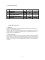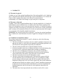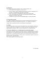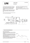
1
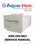
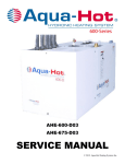
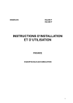
INSTALLATION INSTRUCTIONS
AND USERS MANUAL
HOT WATER STORAGE TANKS
MODEL: ST 1500-3000
FOREWORD
Before attempting to install this water heater please read the installation instructions.
An authorized installer must install the heater and commission it according to the local
valid requirements.
A.O. SMITH CANNOT ACCEPT ANY RESPONSIBILITY FOR GUARANTEE,
SERVICE AND/OR PRODUCT LIABILITY IN THE EVENT OF UNAUTHORIZED
CHANGES, PRODUCT MODIFICATIONS OR REPAIRS.
1
CONTENTS
1. GENERAL
1.1 Description of the heater
1.2 Controls
1.3 Dimensions
1.4 Technical data
3
3
3
5
2. FOR THE INSTALLER
2.1 Installation
2.2 Water connections
2.3 Commissioning
2.3.1 Filling the heater
2.3.2 Heater start-up
2.4 Shutting down
2.5 Maintenance
2.5.1 Anode
2.5.2 Descaling
2.6 Spare parts
5
6
7
7
7
7
7
7
7
8
3. FOR THE END - USER
3.1 Filling the heater
3.2 Start-up of the water heater
3.3 Shutting down
3.4 Maintenance
8
8
8
8
4. WARRANTY
4.1 Warranty in general
4.2. Warranty of the tank
4.3 Conditions for installation and use
4.4 Exclusions.
4.5 Scope of the warranty
4.6 Claims
4.7 No other obligations for A.O. Smith
than those stated in this manual
9
9
9
10
10
10
10
2
1. GENERAL
1.1 Description of the heater
Construction of the heater is in accordance with the European standard for water heaters
or sanitary use. The heaters are suitable for use with a working pressure of up to 7 bar.
The cylindrical tank is made from sheet steel. For protection against corrosion, the inside
of the tank is glass-lined. The tank is also fitted with magnesium anodes for extra
protection against corrosion. A thick, replaceable insulation jacket minimizes heat loss.
1.2 Controls.
ST models are supplied without controls.
1.3 Dimensions
2 Hot water outlet 2”
8
1
2
3
4
5
5
6
6 Recirculation 1¼”
7
8
A
B
C
D
E
F
G
H
Clean out flange
F
1 Cold water inlet/drain 2”
3
Connection sizes
Inlet
Outlet
Anode
Recirculation
connection
T&P connection
Tank diameter
Overall diameter
Height
Height alt inlet
Distance
between 2 “
connections
Height
circulation conn.
height clean out
opening
Height inlet
Clean out
diameter
ST 1500/2000
ST 2500/3000
2"
2"
2"
2"
3/4
3/4
1¼"
1¼"
3/4
3/4
1100
1200
1930/2118
400
1400
1500
1990/2118
480
550/644
500/565
710
690
450
530
135
183
110
110
1.4 Technical specifications
1
Storage capacity
2
Tank heat loss
3
Maximum working pressure
4
Test pressure tank
5
Maximum allowed tank temperature
6
Weight empty
ST 1500/2000 ST 2500/3000
1500/2000
2500/3000
ltr
8.5
10.1
kWh/24h
7
7
bar
12
12
bar
95
95
°C
374/506
637/739
kg
2. FOR THE INSTALLER
2.1 Installation
A qualified, competent installer must install the hot water storage tanks in accordance
with local valid regulations and codes.
Location needs to be chosen to prevent damage in case of tank leakage (e.g. place tank in
a drain pan or near a floor drain of sufficient capacity). For mounting of the jacket see
separate attached Kit installation sheet.
2.2 Water connections
The water heater is suitable for connection to vented, un-vented and pumped pressurized
systems. In each case appropriate valves and fittings should be used to ensure the system
complies with the governing codes and appropriate building requirements. The maximum
working pressure is 7 bars. A typical installation diagram for an un-vented installation is
as follows:
4
6
Back-up
element
1 = drain (on small tanks only)
2 = valve
3 = check valve
4 = pressure relive valve
5 = circulation pump sanitary water
6 = temperature sensor for boiler three way valve
A = circulation line
B = warm water
C = cold water
E = boiler water hot
F = boiler water return
Optional backup elements are available for field installation up to 6 kW input. Models with fixed internal heat exchanger
are also available.
5
2.3 Commissioning
2.3.1
Filling the tank
1. Check if any installed drain valve is closed.
2. Open the cold-water supply valve to the heater
3. Open all hot-water outlets in order to bleed all air from the system. The heater is
filled when cold water runs out of all outlets.
4. Close all hot water taps
2.3.2 Start up
Check if the heater is filled with water and that the primary system is ready. Open water
supply and return valves.
2.4 Shutting down
For longer periods:
1. Close the cold-water tap.
1. If there is any risk of frost damage, drain the tank completely.
2.5 Maintenance
The heater must be checked and cleaned regularly (at least once a year) by an accredited
installer, so that correct operation is guaranteed.
2.5.1 Anodes
The life of the anode is determined by the quality and quantity of the water flowing
through the heater. Therefore, we recommend the anodes to be checked regularly –
preferably simultaneously with an internal inspection of the glass-lined tank. In order to
determine the frequency of replacement of the anode, the waterside of the boiler must be
checked three months after installation. The anodes must be replaced, if more than 60%
has dissolved at any point on their length.
Procedure:
1. Close the cold-water inlet tap.
2. Relieve pressure from the heater completely by opening a hot water tap.
3. Remove the insulation package.
4. Unscrew and inspect the anode. Replace when used for more than 60 %.
5. Replace the anode. Attention: the anode must be in contact with the metal tank. If
the tank and the anode are electrically isolated, the anode cannot function. This
could have a negative effect on the life of the tank.
6. Assemble everything in reverse order.
7. Fill the heater as described in par. 2.2.1.
6
2.5.2 Descaling
Calcium precipitation depends on the water properties and the hot water demand. In
addition, calcium precipitation in the tanks increases at high water temperatures. A clean
out opening is located at the front for inspecting and descaling the tank. The clean out
opening can be reached via the cover plate on the outer jacket of the tank. Empty the tank
before opening the clean out opening. Descaling must be carried out with suitable
descaling agents, which can be ordered form A.O. Smith distributors.
To ensure that the clean out cover is watertight, the flange gasket should be replaced after
every inspection.
2.6 Spare parts
It is important to mention the tank type, model and full serial number when
ordering spare parts. The spare parts can be determined on the basis of these
numbers.
3. FOR THE END USER.
Warning
An accredited installer must install the tank and perform start up of the system.
3.1 Filling the tank
1. Check if drain valve is closed (if mounted).
2. Open the cold-water tap to the heater and all hot-water outlets in order to bleed all air
from the system. The heater is filled when cold water runs out of all outlets.
3. Close all taps at the hot-water outlet points. The tank is now under (water mains)
pressure. At this pressure the pressure relief valve must not release any water.
3.2 Start up of the system.
1. Check if the heater is filled with water and that the primary system is ready.
2. Set the controls on the primary circuit t of the boiler to the required sanitary water
temperature.
3. Open boiler supply and return valves (if installed)
3.3 Shutting down
For longer periods
1. Close the cold-water tap.
2. If there is any risk of frost damage, drain the tank completely.
3.4 Maintenance
The pressure relieve valve must be tested regularly by opening test lever for some
seconds. The water must run out in a full jet. Close lever again, making sure it sets
properly and the valve is not leaking. Check if the drainpipe is open. It is recommended
to arrange for a maintenance contract with the installer.
7
4. WARRANTY
4.1 Warranty in general
If within one year of the original installation date of the tank supplied by A.O. Smith any
part or component other than the tank shall prove upon examination by A.O. Smith, and
in the exclusive opinion of the latter, to be defective in material and/or
workmanship, A.O. Smith will exchange or repair such part or component.
4.2 Warranty of the tank
If within 5 years of the original installation date of the tank supplied by A.O. Smith, the
tank shall prove upon examination by A.O. Smith, and in the exclusive opinion of the
latter, to be leaking due to rust or corrosion from the waterside, A.O. Smith will supply a
complete new tank of equivalent size and quality on ex factory basis. On the replacement
tank a warranty will be granted sufficient to cover the not expired portion of the original
5 year warranty of the originally installed water heater.
WARNING: the warranty period will be reduced to 1 year from the original installation
date, if unfiltered or water softened to less than 70 ppm flows through or remains in the
tank.
4.3 Conditions for installation and use
The warranty ensuing from sections 4.1 and 4.2 will only be valid, if the following
conditions have been met:
a. The tank is installed in accordance with A.O. Smith’s installation instructions for
that specific model, as well as the local installation and building regulations, and
all relevant rules and regulations imposed by the authorities.
b. The tank remains installed in the original installation location.
c. Exclusively potable water, free to circulate at all times, is used (for heating salty
or corrosive water a separately installed heat exchanger is mandatory).
d. The tank is free of damaging scale deposits, due to periodic maintenance;
e. The water pressure and/or water temperature does not exceed the maximum
values stated on the water heater’s type plate and /or in this manual.
f. The tank is located in a non-corrosive atmosphere or area.
g. The tank is fitted with an expansion tank or inlet unit that is approved by the
relevant authorities, that is of sufficient capacity, not exceeding the working
pressure rating as indicated on the tank; the tank is possibly also fitted with a
temperature and pressure relief valve that is approved by the relevant authorities,
and that has been fitted in accordance with A.O. Smith’s installation instructions
for that specific water heater model, and furthermore, the local installation and
building regulations, and all relevant rules and regulations imposed by the
authorities.
h. The anodes have been inspected and renewed when worn for 60% or more.
8
4.4 Exclusions
The warranty ensuing from sections 4.1 and 4.2 will be null and void:
a. If the tank has been damaged by external causes.
b. In case of misuse, neglect (including frost damage), incorrect or improper use of
the tank, or if attempts have been made to repair leaks;
c. In the case of ingress of contaminants or other particles into the tank.
d. If the water conductivity is less than 150 µS/cm and/or the degree of water
hardness is less than 6 °DH/75 ppm.
e. If unfiltered, recycled water flows through the tank, or is stored in the tank.
4.5 Scope of the warranty
A.O. Smith’s obligations ensuing from this warranty are limited to the free delivery ex
Veldhoven store of the parts or the tanks respectively. A.O. Smith is not liable for
carriage, labor, installation and other costs relating to the replacement.
4.6 Claims
Any claim under this warranty must be filed with the dealer who originally sold the tank,
or with any other dealer or supplier of A.O. Smith’s products. The examination of the
tank pursuant to sections 4.1 and 4.2 will be carried out at A.O. Smith discretion.
4.7 No other obligations for A.O. Smith than those stated in this manual
With respect to the tank, respectively the tanks (or parts or components thereof) supplied
as a replacement, A.O. Smith will grant no other warranty or guarantee than the warranty
detailed above. A.O. Smith will not be liable by virtue of this warranty or otherwise for
damage to any persons or property, caused by parts or components, respectively the steel,
glass-lined tank supplied by them.
This warranty applies to the following models:
ST 1500-3000
9
ST 1500-3000 series
Kit installation instructions
1 – Contents of flange kit
Bag A
Flange plate
Designation
Bolts
Gasket
Flange plate
Bag D
Quantity
6
1
1
1
Bag D
Flange collar and cover fixation screws and brackets
Designation
Brackets
Parker screws
Quantite
3
5
Flange collar and cover
Installation manuals
10
2 – Mounting instructions for flange covers, anodes, T&P and insulation package
IMPORTANT:
Start with mounting two plug anodes in the lower and center anode opening on the side of
the tank. In the top anode opening you need to mount the outlet anode with T-piece for
T&P relieve valve (included) and thermometer (not included). Make sure that anodes are
mounted water tight but do make good contact with the metal of the tank.
Mounting of the flange, covers and jacket MUST be done in the indicated sequence.
For further information please refer to the installation manual 0307138RO
Item
1
Bag D, fixing bracket for clean-out collar and cover
Designation
Quantity
Bracket
3
Item
2
3
4
5
Bag A, flange cover
Designation
Bolds.
Gasket
Steel flange cover
Nuts
Quantity
6
1
1
6
!!! In case the unit is supplied with a flexible insulation jacket, now start mounting the insulation
(see overleaf). If the insulation is of the rigid type, proceed as follows:
Bag D: Mounting of clean out collar and cover
Item
6
Designation
parker screws
Quantity
5
11
3 – Mounting instruction for rigid jacket
Nota: top panels, once placed, fixate the jacket.
Center each jacket
segment on one of
the feet ..
4 – Mounting of the flexible jacket
Install the flexible jacket before mounting the clean out collar and cover. The collar serves as
mould to cut the required opening in the jacket.
In case the zipper is difficult to close, it might be neccessary to go through one heatng cycle. A
warmed up jacket is easier to close.
Nota: Jackets and kits are supplied is separate colli.
0307593R0
12