Transcript
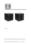
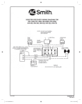
TYPICAL PIPING FOR CONVENTIONAL
SINGLE BOILER INSTALLATION
HW-300 thru HW 670
APPLICATION TYPE DIAGRAM
SEE INSTALLATION MANUAL FOR
COMPLETE INSTRUCTIONS
INSTALL IN ACCORDANCE WITH LOCAL CODES.
SYSTEM NOTES:
• The System Pump must be sized to maintain the minimum
recommended flow rate through the boiler. The pump must
operate continuous or cycle with the boiler.
• The By-Pass is required for systems designed to operate at
flow rate higher than the maximum recommended flow rate
of the boiler.
• This piping method is not recommended for systems designed
to operate with return water temperatures less than 110°F. (See
recommended piping method for Low Temperature Heating Systems
A&E Page E 112.0.)
* PIPE RELIEF VALVE TO OPEN DRAIN.
Model
Inlet / Outlet
Size
20° Temperature Rise
30° Temperature Rise
40° Temperature Rise
HW-300
1 1/4"
GPM
23
PD-Ft/hd
8.0
GPM
15
PD-hd
3.0
GPM
11
PD-Ft/hd
2.0
HW-399
HW-420
1 1/2"
1 1/2"
30
32
16.0
18.0
20
21
7.0
8.0
15
16
5.0
5.5
HW-520
HW-670
2"
2"
39
51
12.0
22.0
24
34
5.0
10.0
20
25
4.0
5.5
June 2007R
Revised
June 1998 (Reviewed March 1999)
© A. O. SMITH CORP. 1998
Printed in the U.S.A.
E 107.0