1
TouchMix™
User Guide
TouchMix-8
TouchMix-16
TD-000472-00-A
*TD-000472-00*
EXPLANATION OF SYMBOLS
The term “WARNING!” indicates instructions regarding personal safety. If the instructions are not followed the result may be bodily injury or death.
The term “CAUTION!” indicates instructions regarding possible damage to physical equipment. If these instructions are not followed, it may result in
damage to the equipment that may not be covered under the warranty.
The term “IMPORTANT!” indicates instructions or information that are vital to the successful completion of the procedure.
The term "NOTE" is used to indicate additional useful information.
The intent of the lightning flash with arrowhead symbol in a triangle is to alert the user to the presence of un-insulated "dangerous"
voltage within the product's enclosure that may be of sufficient magnitude to constitute a risk of electric shock to humans.
The intent of the exclamation point within an equilateral triangle is to alert the user to the presence of important safety, and operating
and maintenance instructions in this manual.
IMPORTANT SAFETY INSTRUCTIONS
WARNING!: TO PREVENT FIRE OR ELECTRIC SHOCK, DO NOT EXPOSE THIS EQUIPMENT TO RAIN OR MOISTURE.
Maximum ambient operating temperature is 40°C (104°F).
DO NOT LEAVE THE POWER SUPPLY UNATTENDED WHEN PLUGGED IN. Always unplug the power supply from the electric outlet
immediately after use.
CAUTION!: Operate this unit with the QSC provided, Class 2 / LPS power supply only; do not substitute.
•
•
•
•
•
•
•
•
•
•
•
•
•
•
•
•
•
•
•
Keep these instructions.
Heed all warnings.
Follow all instructions.
Do not use this apparatus near water.
Do not submerge the apparatus in water or liquids.
Do not use this apparatus in or near water or liquids.
Do not use any aerosol spray, cleaner, disinfectant or fumigant on, near or into the apparatus. Clean only with a dry cloth.
Do not block any ventilation opening. Install in accordance with the manufacturer's instructions.
Do not install near any heat sources such as radiators, heat registers, stoves, or other apparatus (including amplifiers) that produce heat.
Do not defeat the safety purpose of the polarized or grounding-type plug. A polarized plug has two blades with one wider than the other. A
grounding type plug has two blades and a third grounding prong. The wide blade or the third prong are provided for your safety. If the provided
plug does not fit into your outlet, consult an electrician for replacement of the obsolete outlet.
Protect the power cord from being walked on or pinched particularly at plugs, convenience receptacles, and the point where they exit from
the apparatus.
Do not unplug the power supply by pulling on the cord, use the plug.
Inspect the apparatus, including the power supply for signs of external wear and tear or signs of damage. All damage to the apparatus should
be immediately repaired by a QSC authorized service station or QSC International Distributor. Failure to perform necessary repairs could lead to
additional damage or to safety hazards. Failure to perform necessary repairs voids the limited warranty and QSC is not responsible for any injury,
harm or related damages arising from any failure to perform those repairs.
Only use attachments/accessories specified by the manufacturer.
Unplug this apparatus during lightning storms or when unused for long periods of time.
Refer all servicing to qualified service personnel. Servicing is required when the apparatus has been damaged in any way, such as power-supply
cord or plug is damaged, liquid has been spilled or objects have fallen into the apparatus, the apparatus has been exposed to rain or moisture,
does not operate normally, or has been dropped.
The appliance coupler, or the AC Mains plug, is the AC mains disconnect device and shall remain readily operable after installation. On units
equipped with powerCon® connectors, the AC Mains disconnect device is the AC Mains plug only; do not use the appliance coupler.
Adhere to all applicable, local codes.
Consult a licensed, professional engineer when any doubt or questions arise regarding a physical equipment installation.
TD-000472-00-A
ii
Maintenance and Repair
Advance technology, e.g., the use of modern materials and powerful electronics, requires specially adapted maintenance and repair methods. To
avoid a danger of subsequent damage to the apparatus, injuries to persons and/or the creation of additional safety hazards, all maintenance or repair
work on the apparatus should be performed only by a QSC authorized service station or an authorized QSC International Distributor. QSC is not
responsible for any injury, harm or related damages arising from any failure of the customer, owner or user of the apparatus to facilitate those repairs.
FCC Statement
NOTE: This equipment has been tested and found to comply with the limits for a Class B digital device, pursuant to Part 15 of the
FCC Rules.
These limits are designed to provide reasonable protection against harmful interference in a residential installation. This equipment generates, uses
and can radiate radio frequency energy and, if not installed and used in accordance with the instructions, may cause harmful interference to radio
communications. However, there is no guarantee that interference will not occur in a particular installation. If this equipment does cause harmful
interference to radio or television reception, which can be determined by turning the equipment off and on, the user is encouraged to try to correct
the interference by one or more of the following measures:
•
•
•
•
Reorient or relocate the receiving antenna.
Increase the separation between the equipment and receiver.
Connect the equipment into an outlet on a circuit different from that to which the receiver is connected.
Consult the dealer or an experienced radio/TV technician for help.
RoHS STATEMENT
The QSC TouchMix-8 and QSC TouchMix-16 audio mixers are in compliance with European Directive 2011/65/EU – Restriction of Hazardous
Substances (RoHS).
The QSC TouchMix-8 and QSC TouchMix-16 audio mixers are in compliance with “China RoHS” directives. The following chart is provided for product
use in China and its territories:
QSC TouchMix-8 and QSC TouchMix-16 Audio Mixers
部件名称
(Part Name)
有毒有害物质或元素
(Toxic or hazardous Substances and Elements)
铅
(Pb)
汞
(Hg)
镉
(Cd)
六价铬
(Cr(vi))
多溴联苯
(PBB)
多溴二苯醚
(PBDE)
电路板组件
(PCB Assemblies)
X
O
O
O
O
O
机壳装配件
(Chassis Assemblies)
X
O
O
O
O
O
O: 表明这些有毒或有害物质在部件使用的同类材料中的含量是在 SJ/T11363_2006 极限的要求之下。
(O: Indicates that this toxic or hazardous substance contained in all of the homogeneous materials for this part is below the limit requirement
in SJ/T11363_2006.)
X: 表明这些有毒或有害物质在部件使用的同类材料中至少有一种含量是在 SJ/T11363_2006 极限的要求之上。
(X: Indicates that this toxic or hazardous substance contained in at least one of the homogeneous materials used for this part is above the
limit requirement in SJ/T11363_2006.)
Warranty
For a copy of the QSC Limited Warranty, visit the QSC Audio Products website at www.qsc.com
Para una copia de la Garantía Limitada de QSC, visite el sitio web de QSC Audio Products, en www.qsc.com
Pour obtenir une copie de la garantie limitée de QSC, visitez le site de QSC Audio Products à www.qsc.com
Besuchen Sie die Webseite von QSC Audio Products (www.qsc.com) um eine Kopie der beschräenkte Garantie von QSC zu erhalten.
如果您想要QSC有限保修的複印本,请造访QSC音频产品的网站www.qsc.com
TD-000472-00-A
iii
Table of Contents
Maintenance and Repair . . . . . . . . . . . . . . . . . . . . . . . . . . . . . . . . . . . . . . . . . . . . . . . . . . . . . . . . . . . . . . . . . . . .iii
FCC Statement . . . . . . . . . . . . . . . . . . . . . . . . . . . . . . . . . . . . . . . . . . . . . . . . . . . . . . . . . . . . . . . . . . . . . . . . . . . . .iii
RoHS STATEMENT . . . . . . . . . . . . . . . . . . . . . . . . . . . . . . . . . . . . . . . . . . . . . . . . . . . . . . . . . . . . . . . . . . . . . . . . . .iii
Warranty . . . . . . . . . . . . . . . . . . . . . . . . . . . . . . . . . . . . . . . . . . . . . . . . . . . . . . . . . . . . . . . . . . . . . . . . . . . . . . . . . .iii
TouchMix™ How To . . . . . . . . . . . . . . . . . . . . . . . . . . . . . . . . . . . . . . . . . . . . . 1
Register and Update . . . . . . . . . . . . . . . . . . . . . . . . . . . . . . . . . . . . . . . . . . . . . . . . . . . . . . . . . . . . . . . . . . . . . . . . 1
TouchMix Package Contents . . . . . . . . . . . . . . . . . . . . . . . . . . . . . . . . . . . . . . . . . . . . . . . . . . . . . . . . . . . . . . . . . 1
Getting Started . . . . . . . . . . . . . . . . . . . . . . . . . . . . . . . . . . . . . . . . . . . . . . . . . . . . . . . . . . . . . . . . . . . . . . . . . . . . 1
Turn off Demo Mode . . . . . . . . . . . . . . . . . . . . . . . . . . . . . . . . . . . . . . . . . . . . . . . . . . . . . . . . . . . . . . . . . . . . . . . . . . . . 1
Recall a Factory Scene . . . . . . . . . . . . . . . . . . . . . . . . . . . . . . . . . . . . . . . . . . . . . . . . . . . . . . . . . . . . . . . . . . . . . . . . . . . 1
Build a Mix Using Presets. . . . . . . . . . . . . . . . . . . . . . . . . . . . . . . . . . . . . . . . . . . . . . . . . . . . . . . . . . . . . . . . . . . . 2
Name Your Auxiliary Outputs . . . . . . . . . . . . . . . . . . . . . . . . . . . . . . . . . . . . . . . . . . . . . . . . . . . . . . . . . . . . . . . . 3
TouchMix Effects . . . . . . . . . . . . . . . . . . . . . . . . . . . . . . . . . . . . . . . . . . . . . . . . . . . . . . . . . . . . . . . . . . . . . . . . . . . 3
Effects Assignment Example . . . . . . . . . . . . . . . . . . . . . . . . . . . . . . . . . . . . . . . . . . . . . . . . . . . . . . . . . . . . . . . . . . . . . . 3
Name the Effects Channels (or Mixes) . . . . . . . . . . . . . . . . . . . . . . . . . . . . . . . . . . . . . . . . . . . . . . . . . . . . . . . . . . . . . 4
Using the FX Wizard . . . . . . . . . . . . . . . . . . . . . . . . . . . . . . . . . . . . . . . . . . . . . . . . . . . . . . . . . . . . . . . . . . . . . . . . . . . . . 5
Using the Input Channel FX Tab . . . . . . . . . . . . . . . . . . . . . . . . . . . . . . . . . . . . . . . . . . . . . . . . . . . . . . . . . . . . . . . . . . . 6
Using the FX Channel Effect Tab . . . . . . . . . . . . . . . . . . . . . . . . . . . . . . . . . . . . . . . . . . . . . . . . . . . . . . . . . . . . . . . . . . . 7
Using the FX Overview . . . . . . . . . . . . . . . . . . . . . . . . . . . . . . . . . . . . . . . . . . . . . . . . . . . . . . . . . . . . . . . . . . . . . . . . . . . 8
Mute Groups . . . . . . . . . . . . . . . . . . . . . . . . . . . . . . . . . . . . . . . . . . . . . . . . . . . . . . . . . . . . . . . . . . . . . . . . . . . . . . 8
DCA Groups . . . . . . . . . . . . . . . . . . . . . . . . . . . . . . . . . . . . . . . . . . . . . . . . . . . . . . . . . . . . . . . . . . . . . . . . . . . . . . . 9
Save Your Work in a Scene. . . . . . . . . . . . . . . . . . . . . . . . . . . . . . . . . . . . . . . . . . . . . . . . . . . . . . . . . . . . . . . . . . . 9
Using Wi-Fi . . . . . . . . . . . . . . . . . . . . . . . . . . . . . . . . . . . . . . . . . . . . . . . . . . . . . . . . . . . . . . . . . . . . . . . . . . . . . . . 10
On the TouchMix: . . . . . . . . . . . . . . . . . . . . . . . . . . . . . . . . . . . . . . . . . . . . . . . . . . . . . . . . . . . . . . . . . . . . . . . . . . . . . . 10
On your iPad . . . . . . . . . . . . . . . . . . . . . . . . . . . . . . . . . . . . . . . . . . . . . . . . . . . . . . . . . . . . . . . . . . . . . . . . . . . . . . . . . . 10
Homework Completed . . . . . . . . . . . . . . . . . . . . . . . . . . . . . . . . . . . . . . . . . . . . . . . . . . . . . . . . . . . . . . . . . . . . . 11
Sound Check . . . . . . . . . . . . . . . . . . . . . . . . . . . . . . . . . . . . . . . . . . . . . . . . . . . . . . . . . . . . . . . . . . . . . . . . . . . . . 11
Level-Match Your QSC Speakers. . . . . . . . . . . . . . . . . . . . . . . . . . . . . . . . . . . . . . . . . . . . . . . . . . . . . . . . . . . . . . . . . . 11
Phantom Power (+48V) . . . . . . . . . . . . . . . . . . . . . . . . . . . . . . . . . . . . . . . . . . . . . . . . . . . . . . . . . . . . . . . . . . . . . . . . . 11
Work on Your Inputs . . . . . . . . . . . . . . . . . . . . . . . . . . . . . . . . . . . . . . . . . . . . . . . . . . . . . . . . . . . . . . . . . . . . . . . . . . . 12
Simple and Advanced Mode . . . . . . . . . . . . . . . . . . . . . . . . . . . . . . . . . . . . . . . . . . . . . . . . . . . . . . . . . . . . . . . . . . . . . 12
TD-000472-00-A
iv
Auxiliary (Stage Monitor) Mixes . . . . . . . . . . . . . . . . . . . . . . . . . . . . . . . . . . . . . . . . . . . . . . . . . . . . . . . . . . . . . . . . . . 12
Input by Input . . . . . . . . . . . . . . . . . . . . . . . . . . . . . . . . . . . . . . . . . . . . . . . . . . . . . . . . . . . . . . . . . . . . . . . . . . . . . . . . . . . . . . 12
Mix by Mix . . . . . . . . . . . . . . . . . . . . . . . . . . . . . . . . . . . . . . . . . . . . . . . . . . . . . . . . . . . . . . . . . . . . . . . . . . . . . . . . . . . . . . . . . 13
Overview Screen (TouchMTouchMixx and 13 App) . . . . . . . . . . . . . . . . . . . . . . . . . . . . . . . . . . . . . . . . . . . . . . . . . . . . 13
Mix on Faders (TouchMix App Only) . . . . . . . . . . . . . . . . . . . . . . . . . . . . . . . . . . . . . . . . . . . . . . . . . . . . . . . . . . . . . . . . 13
Output Processing . . . . . . . . . . . . . . . . . . . . . . . . . . . . . . . . . . . . . . . . . . . . . . . . . . . . . . . . . . . . . . . . . . . . . . . . . . . . . 13
EQ Tab . . . . . . . . . . . . . . . . . . . . . . . . . . . . . . . . . . . . . . . . . . . . . . . . . . . . . . . . . . . . . . . . . . . . . . . . . . . . . . . . . . . . . . . . . . . . . 13
Limiter Tab . . . . . . . . . . . . . . . . . . . . . . . . . . . . . . . . . . . . . . . . . . . . . . . . . . . . . . . . . . . . . . . . . . . . . . . . . . . . . . . . . . . . . . . . . 13
Filters Tab . . . . . . . . . . . . . . . . . . . . . . . . . . . . . . . . . . . . . . . . . . . . . . . . . . . . . . . . . . . . . . . . . . . . . . . . . . . . . . . . . . . . . . . . . . 14
Presets Tab . . . . . . . . . . . . . . . . . . . . . . . . . . . . . . . . . . . . . . . . . . . . . . . . . . . . . . . . . . . . . . . . . . . . . . . . . . . . . . . . . . . . . . . . . 14
Setup Tab . . . . . . . . . . . . . . . . . . . . . . . . . . . . . . . . . . . . . . . . . . . . . . . . . . . . . . . . . . . . . . . . . . . . . . . . . . . . . . . . . . . . . . . . . . 14
Recording . . . . . . . . . . . . . . . . . . . . . . . . . . . . . . . . . . . . . . . . . . . . . . . . . . . . . . . . . . . . . . . . . . . . . . . . . . . . . . . . . . . . 15
Recording Directory Structure . . . . . . . . . . . . . . . . . . . . . . . . . . . . . . . . . . . . . . . . . . . . . . . . . . . . . . . . . . . . . . . . . . . . . . . . . 16
Playback . . . . . . . . . . . . . . . . . . . . . . . . . . . . . . . . . . . . . . . . . . . . . . . . . . . . . . . . . . . . . . . . . . . . . . . . . . . . . . . . . . . . . . . . . . . 16
Mix Down . . . . . . . . . . . . . . . . . . . . . . . . . . . . . . . . . . . . . . . . . . . . . . . . . . . . . . . . . . . . . . . . . . . . . . . . . . . . . . . . . . . . . . . . . . 16
Tips & TricksLow-Cut Filters (AKA High Pass Filters) . . . . . . . . . . . . . . . . . . . . . . . . . . . . . . . . . . . . . . . . . . . . . 17
Compressor Latch . . . . . . . . . . . . . . . . . . . . . . . . . . . . . . . . . . . . . . . . . . . . . . . . . . . . . . . . . . . . . . . . . . . . . . . . . . . . . 17
About Effects Routing . . . . . . . . . . . . . . . . . . . . . . . . . . . . . . . . . . . . . . . . . . . . . . . . . . . . . . . . . . . . . . . . . . . . . . . . . . 18
About DCA Groups . . . . . . . . . . . . . . . . . . . . . . . . . . . . . . . . . . . . . . . . . . . . . . . . . . . . . . . . . . . . . . . . . . . . . . . . 20
About the TouchMix Compressor Display . . . . . . . . . . . . . . . . . . . . . . . . . . . . . . . . . . . . . . . . . . . . . . . . . . . . . 20
TouchMix™ Reference . . . . . . . . . . . . . . . . . . . . . . . . . . . . . . . . . . . . . . . . . . 21
Getting to Know Your TouchMix . . . . . . . . . . . . . . . . . . . . . . . . . . . . . . . . . . . . . . . . . . . . . . . . . . . . . . . . . . . . . 21
Left Side of the Mixing Surface . . . . . . . . . . . . . . . . . . . . . . . . . . . . . . . . . . . . . . . . . . . . . . . . . . . . . . . . . . . . . . . . . . 21
Right Side of the Mixing Surface . . . . . . . . . . . . . . . . . . . . . . . . . . . . . . . . . . . . . . . . . . . . . . . . . . . . . . . . . . . . . . . . . 22
Backside of the Mixing Surface . . . . . . . . . . . . . . . . . . . . . . . . . . . . . . . . . . . . . . . . . . . . . . . . . . . . . . . . . . . . . . . . . . 23
Home . . . . . . . . . . . . . . . . . . . . . . . . . . . . . . . . . . . . . . . . . . . . . . . . . . . . . . . . . . . . . . . . . . . . . . . . . . . . . . . . . . . . . . . 23
Where and What Things Are on the Home Screen Channels . . . . . . . . . . . . . . . . . . . . . . . . . . . . . . . . . . . . . . . . . . . . . . . . 24
The Nav (Navigation) Strip . . . . . . . . . . . . . . . . . . . . . . . . . . . . . . . . . . . . . . . . . . . . . . . . . . . . . . . . . . . . . . . . . . . . . . . . . . . . 25
Input Channel . . . . . . . . . . . . . . . . . . . . . . . . . . . . . . . . . . . . . . . . . . . . . . . . . . . . . . . . . . . . . . . . . . . . . . . . . . . . 26
Trim . . . . . . . . . . . . . . . . . . . . . . . . . . . . . . . . . . . . . . . . . . . . . . . . . . . . . . . . . . . . . . . . . . . . . . . . . . . . . . . . . . . . . . . . . 26
EQ. . . . . . . . . . . . . . . . . . . . . . . . . . . . . . . . . . . . . . . . . . . . . . . . . . . . . . . . . . . . . . . . . . . . . . . . . . . . . . . . . . . . . . . . . . . 27
Compressor . . . . . . . . . . . . . . . . . . . . . . . . . . . . . . . . . . . . . . . . . . . . . . . . . . . . . . . . . . . . . . . . . . . . . . . . . . . . . . . . . . . 28
Gate . . . . . . . . . . . . . . . . . . . . . . . . . . . . . . . . . . . . . . . . . . . . . . . . . . . . . . . . . . . . . . . . . . . . . . . . . . . . . . . . . . . . . . . . . 29
FX Sends . . . . . . . . . . . . . . . . . . . . . . . . . . . . . . . . . . . . . . . . . . . . . . . . . . . . . . . . . . . . . . . . . . . . . . . . . . . . . . . . . . . . . 30
FX Signal Flow . . . . . . . . . . . . . . . . . . . . . . . . . . . . . . . . . . . . . . . . . . . . . . . . . . . . . . . . . . . . . . . . . . . . . . . . . . . . . . . . 30
TD-000472-00-A
v
Pitch Correct . . . . . . . . . . . . . . . . . . . . . . . . . . . . . . . . . . . . . . . . . . . . . . . . . . . . . . . . . . . . . . . . . . . . . . . . . . . . . . . . . . 31
Auxes . . . . . . . . . . . . . . . . . . . . . . . . . . . . . . . . . . . . . . . . . . . . . . . . . . . . . . . . . . . . . . . . . . . . . . . . . . . . . . . . . . . 32
Presets . . . . . . . . . . . . . . . . . . . . . . . . . . . . . . . . . . . . . . . . . . . . . . . . . . . . . . . . . . . . . . . . . . . . . . . . . . . . . . . . . . . . . . . 33
Setup . . . . . . . . . . . . . . . . . . . . . . . . . . . . . . . . . . . . . . . . . . . . . . . . . . . . . . . . . . . . . . . . . . . . . . . . . . . . . . . . . . . . . . . . 34
Output Channel . . . . . . . . . . . . . . . . . . . . . . . . . . . . . . . . . . . . . . . . . . . . . . . . . . . . . . . . . . . . . . . . . . . . . . . . . . . 35
EQ. . . . . . . . . . . . . . . . . . . . . . . . . . . . . . . . . . . . . . . . . . . . . . . . . . . . . . . . . . . . . . . . . . . . . . . . . . . . . . . . . . . . . . . . . . . 35
Limiter . . . . . . . . . . . . . . . . . . . . . . . . . . . . . . . . . . . . . . . . . . . . . . . . . . . . . . . . . . . . . . . . . . . . . . . . . . . . . . . . . . . . . . . 36
Filters . . . . . . . . . . . . . . . . . . . . . . . . . . . . . . . . . . . . . . . . . . . . . . . . . . . . . . . . . . . . . . . . . . . . . . . . . . . . . . . . . . . . . . . . 37
Presets . . . . . . . . . . . . . . . . . . . . . . . . . . . . . . . . . . . . . . . . . . . . . . . . . . . . . . . . . . . . . . . . . . . . . . . . . . . . . . . . . . . . . . . 38
Setup . . . . . . . . . . . . . . . . . . . . . . . . . . . . . . . . . . . . . . . . . . . . . . . . . . . . . . . . . . . . . . . . . . . . . . . . . . . . . . . . . . . . . . . . 39
QSC Speaker Settings . . . . . . . . . . . . . . . . . . . . . . . . . . . . . . . . . . . . . . . . . . . . . . . . . . . . . . . . . . . . . . . . . . . . . . . . . . 40
Other Recommended Speaker Settings . . . . . . . . . . . . . . . . . . . . . . . . . . . . . . . . . . . . . . . . . . . . . . . . . . . . . . . . . . . . 40
Aux Overview . . . . . . . . . . . . . . . . . . . . . . . . . . . . . . . . . . . . . . . . . . . . . . . . . . . . . . . . . . . . . . . . . . . . . . . . . . . . . . . . . 41
Aux Mix-on-Faders (iPad Only). . . . . . . . . . . . . . . . . . . . . . . . . . . . . . . . . . . . . . . . . . . . . . . . . . . . . . . . . . . . . . . . . . . 42
FX Masters . . . . . . . . . . . . . . . . . . . . . . . . . . . . . . . . . . . . . . . . . . . . . . . . . . . . . . . . . . . . . . . . . . . . . . . . . . . . . . . 43
Effect . . . . . . . . . . . . . . . . . . . . . . . . . . . . . . . . . . . . . . . . . . . . . . . . . . . . . . . . . . . . . . . . . . . . . . . . . . . . . . . . . . . . . . . . 43
FX Masters − EQ . . . . . . . . . . . . . . . . . . . . . . . . . . . . . . . . . . . . . . . . . . . . . . . . . . . . . . . . . . . . . . . . . . . . . . . . . . . . . . . 43
Preset. . . . . . . . . . . . . . . . . . . . . . . . . . . . . . . . . . . . . . . . . . . . . . . . . . . . . . . . . . . . . . . . . . . . . . . . . . . . . . . . . . . . . . . . 44
Setup . . . . . . . . . . . . . . . . . . . . . . . . . . . . . . . . . . . . . . . . . . . . . . . . . . . . . . . . . . . . . . . . . . . . . . . . . . . . . . . . . . . . . . . . 45
FX Overview . . . . . . . . . . . . . . . . . . . . . . . . . . . . . . . . . . . . . . . . . . . . . . . . . . . . . . . . . . . . . . . . . . . . . . . . . . . . . . . . . . 45
Basic Chorus . . . . . . . . . . . . . . . . . . . . . . . . . . . . . . . . . . . . . . . . . . . . . . . . . . . . . . . . . . . . . . . . . . . . . . . . . . . . . . . . . . 46
Pitch Shift . . . . . . . . . . . . . . . . . . . . . . . . . . . . . . . . . . . . . . . . . . . . . . . . . . . . . . . . . . . . . . . . . . . . . . . . . . . . . . . . 46
Dense Reverb . . . . . . . . . . . . . . . . . . . . . . . . . . . . . . . . . . . . . . . . . . . . . . . . . . . . . . . . . . . . . . . . . . . . . . . . . . . . . . . . . 47
Lush Reverb . . . . . . . . . . . . . . . . . . . . . . . . . . . . . . . . . . . . . . . . . . . . . . . . . . . . . . . . . . . . . . . . . . . . . . . . . . . . . . . . . . 47
Mono and Stereo Delay . . . . . . . . . . . . . . . . . . . . . . . . . . . . . . . . . . . . . . . . . . . . . . . . . . . . . . . . . . . . . . . . . . . . . . . . . 48
Talkback / Noise . . . . . . . . . . . . . . . . . . . . . . . . . . . . . . . . . . . . . . . . . . . . . . . . . . . . . . . . . . . . . . . . . . . . . . . . . . 48
Phantom Power . . . . . . . . . . . . . . . . . . . . . . . . . . . . . . . . . . . . . . . . . . . . . . . . . . . . . . . . . . . . . . . . . . . . . . . . . . . 49
Phones and Monitor . . . . . . . . . . . . . . . . . . . . . . . . . . . . . . . . . . . . . . . . . . . . . . . . . . . . . . . . . . . . . . . . . . . . . . . 49
Mixer Setup . . . . . . . . . . . . . . . . . . . . . . . . . . . . . . . . . . . . . . . . . . . . . . . . . . . . . . . . . . . . . . . . . . . . . . . . . . . . . . 50
Global and Utility Functions . . . . . . . . . . . . . . . . . . . . . . . . . . . . . . . . . . . . . . . . . . . . . . . . . . . . . . . . . . . . . . . . . . . . . 50
Connect the iPad . . . . . . . . . . . . . . . . . . . . . . . . . . . . . . . . . . . . . . . . . . . . . . . . . . . . . . . . . . . . . . . . . . . . . . . . . . . . . . . . . . . . 51
On your iPad. . . . . . . . . . . . . . . . . . . . . . . . . . . . . . . . . . . . . . . . . . . . . . . . . . . . . . . . . . . . . . . . . . . . . . . . . . . . . . . . . . . . . . . . 51
Troubleshooting the Wi-Fi/iPad Connection . . . . . . . . . . . . . . . . . . . . . . . . . . . . . . . . . . . . . . . . . . . . . . . . . . . . . . . . . . . . . 51
Scenes. . . . . . . . . . . . . . . . . . . . . . . . . . . . . . . . . . . . . . . . . . . . . . . . . . . . . . . . . . . . . . . . . . . . . . . . . . . . . . . . . . . 52
TD-000472-00-A
vi
DCA Groups . . . . . . . . . . . . . . . . . . . . . . . . . . . . . . . . . . . . . . . . . . . . . . . . . . . . . . . . . . . . . . . . . . . . . . . . . . . . . . 53
About DCA Groups . . . . . . . . . . . . . . . . . . . . . . . . . . . . . . . . . . . . . . . . . . . . . . . . . . . . . . . . . . . . . . . . . . . . . . . . . . . . . 53
Mute Groups . . . . . . . . . . . . . . . . . . . . . . . . . . . . . . . . . . . . . . . . . . . . . . . . . . . . . . . . . . . . . . . . . . . . . . . . . . . . . 53
About Mute Groups . . . . . . . . . . . . . . . . . . . . . . . . . . . . . . . . . . . . . . . . . . . . . . . . . . . . . . . . . . . . . . . . . . . . . . . . . . . . 53
Mute Groups Mute Screen . . . . . . . . . . . . . . . . . . . . . . . . . . . . . . . . . . . . . . . . . . . . . . . . . . . . . . . . . . . . . . . . . . . . . . . . . . . . 53
Mute Group Edit Screen . . . . . . . . . . . . . . . . . . . . . . . . . . . . . . . . . . . . . . . . . . . . . . . . . . . . . . . . . . . . . . . . . . . . . . . . 54
Menu. . . . . . . . . . . . . . . . . . . . . . . . . . . . . . . . . . . . . . . . . . . . . . . . . . . . . . . . . . . . . . . . . . . . . . . . . . . . . . . . . . . . 54
FX Wizard . . . . . . . . . . . . . . . . . . . . . . . . . . . . . . . . . . . . . . . . . . . . . . . . . . . . . . . . . . . . . . . . . . . . . . . . . . . . . . . . 55
Gain Wizard . . . . . . . . . . . . . . . . . . . . . . . . . . . . . . . . . . . . . . . . . . . . . . . . . . . . . . . . . . . . . . . . . . . . . . . . . . . . . . 56
Record / Playback . . . . . . . . . . . . . . . . . . . . . . . . . . . . . . . . . . . . . . . . . . . . . . . . . . . . . . . . . . . . . . . . . . . . . . . . . 57
Main Screen . . . . . . . . . . . . . . . . . . . . . . . . . . . . . . . . . . . . . . . . . . . . . . . . . . . . . . . . . . . . . . . . . . . . . . . . . . . . . . . . . . 57
Recording Setup . . . . . . . . . . . . . . . . . . . . . . . . . . . . . . . . . . . . . . . . . . . . . . . . . . . . . . . . . . . . . . . . . . . . . . . . . . . . . . . 58
2-Channel − Playback and Record . . . . . . . . . . . . . . . . . . . . . . . . . . . . . . . . . . . . . . . . . . . . . . . . . . . . . . . . . . . 59
2-Track Recording Setup . . . . . . . . . . . . . . . . . . . . . . . . . . . . . . . . . . . . . . . . . . . . . . . . . . . . . . . . . . . . . . . . . . . . . . . . 59
2-Track Playback EQ . . . . . . . . . . . . . . . . . . . . . . . . . . . . . . . . . . . . . . . . . . . . . . . . . . . . . . . . . . . . . . . . . . . . . . . . . . . . 59
Dimensions . . . . . . . . . . . . . . . . . . . . . . . . . . . . . . . . . . . . . . . . . . . . . . . . . . . . . . . . . . . . . . . . . . . . . . . . . . . . . . 60
TouchMix-8 . . . . . . . . . . . . . . . . . . . . . . . . . . . . . . . . . . . . . . . . . . . . . . . . . . . . . . . . . . . . . . . . . . . . . . . . . . . . . . . . . . . 60
TouchMix-16. . . . . . . . . . . . . . . . . . . . . . . . . . . . . . . . . . . . . . . . . . . . . . . . . . . . . . . . . . . . . . . . . . . . . . . . . . . . . . 61
Specifications . . . . . . . . . . . . . . . . . . . . . . . . . . . . . . . . . . . . . . . . . . . . . . . . . . . . . . . . . . . . . . . . . . . . . . . . . . . . 62
Block Diagram . . . . . . . . . . . . . . . . . . . . . . . . . . . . . . . . . . . . . . . . . . . . . . . . . . . . . . . . . . . . . . . . . . . . . . . . . . . . 63
TD-000472-00-A
vii
TouchMix™ How To
Register and Update
STOP
We know you want to get right to using your TouchMix, but before you do please stop and take a moment to visit www.qsc.com and register your
TouchMix. By registering you can…
• Download TouchMix firmware so that your mixer has all the latest features, refinements and performance enhancements.
• Sign up to be notified of future updates.
• Check to see if you are eligible for free extended warranty coverage.
While you’re there, you can also find videos and other tools to help you get the most from your TouchMix.
TouchMix Package Contents
1. Quick-Start Guide (TD-000445)
1. USB Wi-Fi adaptor (installed in mixer’s USB port)
1. Warning Information Sheet
1. Power supply with IEC cable (AC connector type varies by region)
1. Limited Warranty (TD-000453-01 English)
1. TouchMix carrying case
1. TouchMix-16 or TouchMix-8
Getting Started
You just got your new TouchMix and can’t wait to try it out on your next show. But since TouchMix is a digital mixer there are lots of things you can do
off-line to save time during setup and help you get acquainted with your mixer. We highly recommend spending a little quality time with the mixer
before taking it to a show for the first time.
Turn off Demo Mode
Demo mode is a looping slide show that plays on the TouchMix as a factory default to give prospective buyers an overview of the mixer. Once you
have purchased your TouchMix, you’ll probably want to turn Demo Mode off – even though our graphics guys are really proud of how it looks.
To Disable Demo Mode:
Menu
Mixer Setup
Demo Mode: Off
Recall a Factory Scene
What is a Scene?
A Scene is a group of settings that are saved and can be recalled at a later time. A Scene includes all channel-processing settings, channel Names,
Phantom Power settings, Effects selections, DCA and Mute Group assignments. Scenes also include level settings. Factory scenes are stored with input
faders at minimum to prevent any surprises (feedback, music at 20 dB above the threshold of pain, etc.) when the scene is recalled.
QSC loads TouchMix with pre-defined scenes for various kinds of performances. You can find the one that’s most like the show you’ll be mixing and
start there.
Select a Scene:
Contemporary Band
Scenes
To Recall a Factory Scene: Menu
Recall
Yes
Horn Band...
You’ll see a list of Factory programmed scenes. Select one and touch Recall. Once you’ve recalled a scene you can make modifications to suit the show
you’re mixing.
TD-000472-00-A
1
The factory scenes list includes a scene named Default. This scene will “zero” the mixer by returning all controls to their factory settings.
To Zero the TouchMix:
Menu
Scenes
Recall
Default
Yes
If you'd like to navigate around the mix and see what the recalled settings are, return to the Home screen.
To Return to the Home screen:
Build a Mix Using Presets
What is a Channel Preset?
A Channel Preset is a group of settings, for a single channel, that are saved and can be recalled for use at a later time. A Channel Preset includes the
channel Name, Phantom power setting, and values for the channel EQ, Compressor, and Gate.
You can start by recalling channel Presets individually. TouchMix Presets were programmed to work with common microphones in real, live sound
applications by skilled and experienced concert-sound mix-engineers. And they work. People who have used TouchMix report great results using the
presets with little or no modification.
Presets
In 1
To Select Channel Presets:
Inputs 1-8
1. Make sure that the Factory / User switch is in the Factory position.
2. In the left window you’ll see a list of instrument categories. Touch an instrument category name and a list of specific instruments appears in the
middle window.
3. Select a type of instrument and the right window will display a list of options for the instrument. There may be options with and without gates
and compressors as well as options for various types of microphones and pick-ups or different styles of music. Select the one that seems best for
your application.
To Learn About the Selected Preset:
To Recall the Preset:
Preset Name
Preset Name
Select any item
Preset Info
Recall
Select any item
Yes
You’ve just dialed in the settings for an input channel. You’ll also notice that the channel has been given a name that corresponds with the instrument
you selected. You can leave the name as is or rename the channel.
To Rename a Channel:
Go to the Next Channel:
Setup
Type new name
Next
Repeat the process until you’ve set up all the channels you need.
TD-000472-00-A
2
Enter
Name Your Auxiliary Outputs
What is an Auxiliary?
In addition to the Main L/R (left/right) output mix, TouchMix is also capable of controlling eight additional output mixes (six mono and two stereo).
These additional mixes are known as Auxiliaries, or “Auxes” for short.
The auxiliary outputs are typically used to drive stage monitor speaker systems or in-ear monitors (IEM) for performers. In some instances they may
be used for a recording mix, audio feed to video or a send to an overflow area. In any case, it makes sense to label the auxiliary outputs to help keep
them straight during use. Type in a name for the output – it could be the name of the performer who gets that mix or it could be something like
“Singers” or “Horns” or “Video” or “Patio”.
Aux 1
To Name an Auxiliary Output:
Setup
Type new name
Enter
Aux Outputs
TouchMix Effects
Audio effects (FX) such as reverb, delay, chorus, pitch shift (pitch change) and pitch correct are essential in today’s audio production. TouchMix
provides many users with more and better effects processing than they’ve ever had before. Using effects can be a bit intimidating so this section helps
you use your TouchMix most effectively.
See "Tips & TricksLow-Cut Filters (AKA High Pass Filters)" on page 17 to learn more about effects.
Imagine this – inside TouchMix is a virtual equipment warehouse. In the warehouse are 24 effects processors ready for use on the four FX mixes (FX1
– FX4). There are…
1
1
1
2
2
2
1
3
4
Four Lush Reverb Processors
4
Four Dense Reverb Processors
4
Four Chorus Processors
1
3
1
3
2
2
2
3
3
3
4
Four Pitch Shift Processors
4
Four Mono Delay Processors
4
Four Stereo Delay Processors
You can choose any combination of four in your mix. You can have a different Processor assigned to each effects mix, use four instances of the same
processor or mix and match as you like.
Each of these processors have multiple presets. The reverb processors, for example have presets simulating various sizes of rooms and halls as well as
reverb plates. In addition, there are brighter and darker sounding variations.
Along with the above effects, there is a Pitch-Corrector effect that can be assigned to any one of the input channels.
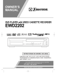
Effects Assignment Example
The first thing to think about is what you want to do with your effects. Here’s a band input list that includes effects. The effects listed correspond
with the factory default presets. Don’t be afraid to use the factory default settings. We chose them to be generally useful in lots of situations.
In this example:
• The lead vocal is sent to a 250 msec. delay that is mixed in at a low level to provide a bit of thickening.
• Horns and all the vocals are given a bit of “space” with a Medium Hall Reverb.
• The snare and toms all have a Medium Plate Reverb applied to them. (Plate reverb is a go-to effect for drums.)
• Note that you can send a channel to more than one effect. Here, the horns are also sent to a Pitch Shift effect with a Light Detune preset. This will
provide a subtle doubling of the horns.
TD-000472-00-A
3
• Other instruments either don’t need any effects or have their own effects (guitar pedals, internal effects on keyboards).
Input
Instrument
1
Kick
2
Snare
3
Hi Hat
4
5
6
Overhead R
7
Overhead L
8
Bass
9
Guitar
10
FX Send
Effect Processor FX Preset Name
3
Dense Reverb
D Live Plate Med
Rack Tom
3
Dense Reverb
D Live Plate Med
Floor Tom
3
Dense Reverb
D Live Plate Med
Sax
2
4
Lush Reverb
Pitch Shift
L Med Hall
Light Detune
11
Trumpet
2
4
Lush Reverb
Pitch Shift
L Med Hall
Pitch-Light Detune
12
Keys R
13
Keys L
14
Lead Vocals
1
2
Mono Delay
Lush Reverb
Mono 250 Delay
L Med Hall
15
Backing Vocal
2
Lush Reverb
L Med Hall
16
Backing Vocal
2
Lush Reverb
L Med Hall
Once you’ve thought about what effects you want to use, you can go to your TouchMix and start setting up your effects. Following are several ways to
set up and control your TouchMix effects.
Name the Effects Channels (or Mixes)
Before we start using the effects, let's take a moment to name our effects channels.
In the middle of a show it’s easy to forget which effect was intended for what instruments. You can name the effects mixes to help keep track. For
example, you might name an FX channel “Voc Delay” or “Drum Rev”.
FX 1
To Name FX channels:
Setup
FX Masters
TD-000472-00-A
4
Type new
name
Enter
Using the FX Wizard
The FX Wizard is the easiest and fastest way to set up your effects. Only effects that work for the Source and Type of input you have selected will be
shown. So any effect you select using the wizard will be a valid one although it may or may not work in the context of your mix.
Here’s how to use it.
To Select and Assign Effects (FX) Using the Wizard: Wizard
FX
Wizard
FX1
You’re now looking at the Wizard for FX1.
Select a Preset:
Type
Source
FX Style
1. Use the Master Encoder or touch-and-drag to scroll up and down the list to see
all the selections. Select one item from each list.
Recall
2. Touch
. The Preset is now loaded, and the name is displayed below
the Type window.
2
or
1a
1b
3. With the Preset loaded, it’s time to decide which input channels you’re going to
send (or feed) to FX1.
Select Inputs to feed FX1:
In 1
through
Adjust Effect Master (Return) Level:
4. Use the FX1 Master fader to adjust the amount of effect heard in the main mix.
Send the Effect to Monitors:
Aux 1
3
Stereo in
19/20
The buttons under “Select Inputs to feed” represent the input channels. Just decide
which channels you want the effect to apply to and touch the corresponding
button. The selected channels are now feeding the effect processor.
through
1c
4
5
— Figure 1 —
— Figure 2 —Note: TouchMix App is shown, TouchMix
display is slightly different.
Aux 9/10
5. Is the performer going to want to hear the effect in the stage monitors or in-ear monitors? If so, it’s easy to send it there. Just use the "Select Aux
Outputs (monitors) to receive: FX1" buttons to tell your mixer where the effect should go.
6. You’ve still got three more effects available so touch one of the tabs at the top of the screen to set up another effect.
TD-000472-00-A
5
Using the Input Channel FX Tab
You can also operate your effects from the input channel area of your mixer.
In 1
To Run Effects from the Input Channel:
FX
Inputs 1-8
Welcome to the channel FX screen. From here you can…
Select an FX Processor:
1
Select a Different Processor:
2
3
4
FX
Lush Reverb
None
1
Select a Preset:
Send to the Effect:
-40
2
3
Presets
4
-20
-10
-5
U
5
10
Cancel
See "Select a Preset:" on page 5. Press Home to come back.
Adjust the fader for each effect you want to use on this channel.
Adjust Global FX Parameters (Advanced Mode Only):
Delay
Feedback
1170
31.0
mSec
%
These controls are called "global" because all channels using this FX mix are affected by these controls. The Sends fader, however is adjusted for each
individual channel.
Blend
Using Pitch Correct:
Enable
75%
Dry
Wet
Key
C/D
Correct-Rate
5.0
(Slow-Fast)
There is one Pitch-Correct processor available on the mixer. Touch the Enable button to assign it to the currently selected channel.
◦ Use the Blend control to vary the mix between corrected (wet) and uncorrected (dry) signal. 100% wet is used to correct pitch. A blend
between wet and dry is used to provide a doubling effect.
◦ Use the Key control to select a music key. This helps Pitch Correct be more accurate in determining what the intended note is.
◦ Use the Correct Rate control to adjust how quickly the pitch correction tracks.
TD-000472-00-A
6
Using the FX Channel Effect Tab
1
2
Go to the FX Channel Effect Tab (From the Input Channel FX tab):
3
4
The FX Master Effect tab offers control over advanced Effects functionality.
FX 1
To Access the FX Master Effect Tab:
Effect
FX Masters
This is where you can select which processor is associated with the selected FX mix or channel.
Select an FX Processor:
To Select a Processor:
FX
Touch the FX Processor you wish to assign to this FX Channel.
Lush Reverb
None
Cancel
You can also select a processor preset.
To Select an Effect preset:
Preset
Mono 250 Delay
Select a Preset from
one of the three lists.
Recall
Info
NOTE: Each processor has user adjustable parameters. Press
more information.
Effect
Yes
then under FX Panels touch
<Effect Name>
To Adjust the Level of the Effect Sent to the Main L/R Output:
Use the FX Master fader to the right of the FX panel to adjust the amount of effect heard in the main speaker system.
To Adjust the Level of the Effect Sent to the Auxiliary Outputs:
Aux 1
Aux 2
Aux 3
Aux 4
Aux 5
Aux 6
3.0
3.0
3.0
3.0
3.0
3.0
Aux 7/8 Aux 9/10
3.0
3.0
Use the "FX Returns to Monitors" knobs to control the amount of effect heard in the monitor speakers.
The FX panel also includes EQ, Preset and Setup tabs. These function in the same way as the corresponding input channel screens.
TD-000472-00-A
7
for
Using the FX Overview
If you would prefer to see the send and return levels for all your effects at once, the
FX overview is where you want to go.
To use the FX Overview: Menu
FX
Overview
1
2
3
1. The columns are the Input channels. Use the Nav Strip to change the group of
Input channels. Each Input channel has its own FX Sends 1 – 4.
4
2. The rows are the FX Mixes. Each FX Mix has one FX Send from each Input
Channel, an FX Master fader, and an Effect assignment ("none" can also
be assigned).
3. FX Master fader – The FX Master fader controls the overall output level of the
FX Mix to the Main L/R outputs. Note that the FX Master does not affect the level
of the Effect sent to the Aux channels.
— Figure 3 —
4. Effect Processor – Indicates the type of Effect currently being applied to the FX Mix.
So that’s about it for effects. We worked hard on the TouchMix effects and know that they sound superb and will enhance your performances. You can
dive in deep or just use the wizards, factory defaults and presets. Either way, you now have the tools for a great sounding show.
Mute Groups
There are many times when it is useful to mute some of the inputs and outputs. For example, you might want to mute everything but a stereo input
for break music. Or you may wish to mute all the musicians’ channels when the pastor is speaking. Or there may be a part of your show when the
band leaves the stage while one member does a solo number. Mute groups let you mute multiple inputs and outputs from a single button.
Select
Mute
Groups
To set up Mute Groups:
1
Edit
In 2
Mute 1
Continue selecting channels as you wish.
Mute
To Name the Mute Group:
Type new name
Select another Mute group to set up or touch Close Edit to finish.
To use Mute Groups:
Mute
Groups
1
1
Mute 1
Mute 1
Mute
Mute
NOTE: When a channel is muted by a Mute Group, the channel Mute button on the Home screen looks like:
TD-000472-00-A
8
Mute
DCA Groups
TIP: See "Tips & TricksLow-Cut Filters (AKA High Pass Filters)" on page 17 for more on DCA’s.
A DCA groups faders together so the overall level of all the channels in the group can be controlled by a single DCA fader. A DCA fader does not
change the position of any of the faders in the group.
IMPORTANT: Here is an important thing to know – if the DCA master fader is at 0.0 (the unity (U) mark), it does nothing to the level
of an assigned channel. The DCA adds or subtracts level. Move the DCA Fader up 3 dB and everything it’s assigned to will increase by
3 dB. Move it down 3 dB and – well you probably figured that out. Remember that assigning or unassigning a channel to a DCA Group
can cause a sudden change in the level of the channel so it’s good practice to have the DCA master at 0.0 when changing assignments.
5
DCA 1
To Setup a DCA Group:
DCA 5
DCA Groups
In 2
Continue selecting channels as you wish.
Select
You can assign inputs, outputs and FX Master faders to a DCA. If you assign an input, and the output to which it's going to the same DCA, changes you
make using the DCA are doubled for the input. Raise the DCA 3 dB, the input is effectively raised 6 dB.
Type new name
To Name the DCA group:
To Mute a DCA Group:
Mute
DCA Groups
When you mute a DCA, all channels assigned to that DCA are muted. If a channel is muted by the channel Mute button, or a Mute Group, the DCA
does not un-mute the channel when the DCA is un-muted.
Save Your Work in a Scene
You’ve put some effort into setting up your mix so now would be a great time to save it. A Scene is a snapshot of all the settings on the mixer.
To Save Your Scene: Menu
To Name Your Scene:
Scenes
Save/Save As...
Type new name
Save Location:
To Save Your Scene:
TD-000472-00-A
Internal
External
(USB)
Save
9
Using Wi-Fi
Make sure that the included USB Wi-Fi adapter is installed in one of the mixer’s USB ports.
IMPORTANT: QSC does not support the use of Wi-Fi adapters other than those included with the mixer or that have been specifically
approved by QSC.
The TouchMix App requires iPad iOS version 6.0 or later.
On the TouchMix:
You can leave the Mixer Name and Password as is but it’s probably a good idea to change them. Otherwise, anyone with the TouchMix App can run
your mixer; and you know how musicians love pranks. Speaking of the TouchMix App – you’ll want to get that installed on your iPad or the Wi-Fi set
up is kind of pointless. Visit the App Store and search for QSC TouchMix.
To Change Wi-Fi Settings: Menu
Mixer Setup
The Mixer Name (Network SSID) can have up to ten characters.
Mixer Name (Network SSID):
Change the Mixer Name (Network SSID):
New Mixer Name
The Network Password must be ten digits.
Network Password:
Change the Password:
1234567890
Now you're ready to connect the iPad to the Mixer's network.
On your iPad
To Connect your iPad: Settings > Wi-Fi > Select the TouchMix network. It's identified by the SSID.
NOTE: If you do not see the TouchMix network after several minutes, reset the TouchMix Network.
Menu
Mixer Setup
Reset Network
1. After selecting the TouchMix SSID, you'll see dialog letting you know the network you're joining is not connected to the Internet. Touch
“Join Anyway”.
2. The next screen is where you enter your Password.
3. When your iPad is connected, touch the SSID Name again. On the details page, turn on Auto-Join.
4. Wait for a minute or two. This gives the iPad and network time to get their act together.
5. Open the TouchMix App.
6. The Link field in the upper right corner of the iPad screen shows the network name, and a green LED. Your iPad is connected.
If the TouchMix App has difficulty connecting to your mixer, it may be necessary to reset your iPad by holding down the sleep/wake and Home buttons
until the screen turns off and on again.
With a few minor exceptions, the TouchMix App operates identically to the actual mixer. The App and mixer screen selections don’t follow each other
so you can have one section of the mixer being controlled by your tablet while another section is being operated from the mixer’s user interface.
Troubleshooting
Refer to the "Troubleshooting the Wi-Fi/iPad Connection" on page 51 in the TouchMix Reference section.
TD-000472-00-A
10
Homework Completed
That’s it. You’ve done your homework. Of course you’ll need to adjust the input gain and get your mix levels at the gig but you’re way more than halfway to a great, professional-sounding mix.
Sound Check
Before connecting anything, plug in your TouchMix and make sure that all the inputs and Auxiliary Outputs are muted. This will prevent uncontrolled
feedback if a microphone is patched into a hot channel.
To Mute Channels:
Mute
Mute
Inputs 1-8
Inputs 9-16
Mute
Stereo In / 2 Trk
Aux Outputs
In each of the groups of faders, press the Mute button for all channels. Now you can connect the mixer to sources and speaker systems.
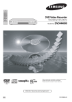
Level-Match Your QSC Speakers
If you’re using one of the following QSC Loudspeakers:
input-gain setting for your loudspeaker.
Main
For Main L/R:
OR
Setup
View Settings
Aux 1
For Aux 1-8:
your TouchMix tells you the optimum
Setup
View Settings
Aux Outputs
In the popup all you need to do is touch the button associated with your loudspeaker,
and then adjust your loudspeakers as instructed in the popup.
You're probably wondering - why we recommend using input B. Input A has a switch
that adds gain for use with a direct microphone input. If this switch is set incorrectly
the speaker's input will be far too hot. Using input B eliminates the possibility of such a
mistake.
Select your QSC Speaker
K Series
K Series
KW Series
KLA Series
These settings will give you the optimum signal to noise performance and get the most
from your QSC powered speakers. The mixer’s output meters will reflect when you’re
“running out of speaker”. Note that you will see the “Limit” light on your speakers
illuminate as the mixer drives them harder during louder portions. This is normal and is
just the speaker’s internal DSP doing its job.
0dB
K Series
KW Series
OFF
+10dB
KLA Series
GAIN B
Rotate 4 detents (clicks) past zero
Done
— Figure 4 —
Phantom Power (+48V)
Most condenser microphones and some direct boxes require phantom power from the mixer. On TouchMix, phantom power may be turned on or off
on a per channel basis. Make sure that phantom power is on for those channels that need it and off for those that don’t.
Guitar
To Enable or Disable Phantom Power (+48V):
Cond Mic
To exit
+48V
+48V
Phantom power is also accessible from the channel Setup screens.
TD-000472-00-A
11
Work on Your Inputs
Ask the performers in turn to do what they do to make their audio contribution to the performance. Without
un-muting their channels, bring the channel’s input gain Trim up while watching the channel meter on the Home
screen. What you are looking for is a meter that is bouncing around the 0 mark when the performer is producing
a normal output level.
Not
Acceptable
Acceptable
0
0
0
0
TIP: During sound check performers will usually not play as loudly as they do in an actual
performance so keep this in mind and allow a little extra headroom.
With the performer performing, un-mute the channel and bring the fader up until the desired performance level
is reached.
If you are using one of the internal channel presets, this channel should already be sounding good. If it’s not what
you’re looking for, try some of the other preset choices. For most instruments and musical styles, there will be a
preset that works well. If not, you'll need to dive into the channel and dial it in manually.
— Figure 5 —
In 1
To Adjust Channel Parameters:
Inputs 1-8
At the top of the screen, select the tab for the channel processing element you want to work on.
Simple and Advanced Mode
TouchMix offers two modes of operation.
• Simple Mode – Presents the user with a reduced set of controls. It’s important to know that switching into Simple mode does not alter the values
of any Advanced-mode controls.
• Advanced Mode – Presents all mixer controls to the user.
You can select Simple and Advanced modes individually for an EQ, Gate, Compressor or Effect. Note that the Stereo and Mono Delays do not have a
Simple mode. Look for the Simple button on the screen. Or you can make the selection globally.
To Globally Select Simple / Advanced Mode: Menu
Simple
OR
Advanced
Yes
Auxiliary (Stage Monitor) Mixes
There are two general approaches to setting up stage monitor mixes:
Input by Input
With all the performers on stage, ask each performer in turn to play or sing just one thing (Kick, Snare, Guitar, Sax, etc). Ask each performer how
much of that instrument they want in their monitor. Our guess is that they will all say “that’s plenty” during sound check and then ask for lots more
after the first song – just sayin’.
Auxes
In 1
To Set Up Monitor Mixes:
Inputs 1-8
You will see sliders representing the send levels to all the aux mixes. Auxes 7/8 and 9/10 are stereo auxes so each has a Pan control. If any mono auxes
are linked they also have Pan controls.
Adjust
-40
-20
TD-000472-00-A
-10
-5
U
5
10
for each performer in turn then use the
Prev
12
and
Next
buttons to move through the channels.
Mix by Mix
In this approach, you'll dial in a complete monitor mix for one performer at a time. There are two ways of doing this.
Overview Screen (TouchMix and TouchMix App)
One way is from the Aux Overview screen. The Aux Overview screen, as the name implies, provides a view of all the aux mixes for a bank of channels
at once, in matrix format.
To Set Up Monitor Mixes:
Aux
OR
Inputs 1-8
OR
Inputs 9-16
Stereo In / 2 Trk
Each horizontal row of sliders represents one of your monitor mixes. If you have named your Aux outputs, the name displays above the Master slider
on the right of the screen. Auxes 7/8 and 9/10 are stereo auxes so each has a Pan control. If any mono auxes are linked they also have Pan controls.
Touch any
to select and change its value using
.
Mix on Faders (TouchMix App Only)
This screen presents the controls for one Aux Mix at a time using the same style of large faders as the Home screen.
To Set Up Monitor Mixes:
Aux
Aux
Aux Mix
Select
Touch the Aux Mix Select to go to the mix you want, then use the faders to adjust the sends to the selected Aux Mix. If necessary, select another bank
of channels. Mix on Faders is the perfect method for a performer using the TouchMix App to dial in their own stage monitor – they see only the
channel sends for their monitor.
Output Processing
Like the input channels, the outputs (Main L/R and Aux Outputs) have their own processing.
To access Main Output Processing:
Main
Aux 1
To access Aux Output Processing:
Aux Outputs
EQ Tab
For the Main and Aux 1 – 8 outputs, the EQ tab displays the 1/3 octave graphic equalizer.
To better fit the screen, the equalizer has been divided into four sections – Low, Low-Mid,
High-Mid and High. The four windows will display the setting of all faders. Touch any of
the windows to work on that part of the frequency spectrum.
For Auxes 7/8 and 9/10 the EQ is parametric and is identical to that found on input
channels.
Low
Low Mid
High Mid
31.5 to
125 Hz
160 to
630 Hz
800 Hz to
3.15 kHz
— Figure 6 —
Limiter Tab
Displays the limiter and its controls. We strongly encourage the use of the limiter for In Ear Monitors.
TD-000472-00-A
13
High
4 to
16 kHz
Filters Tab
There are multiple types of filters presented here.
• Low-Cut / High-Cut filters – These filters are used to roll off high or low frequency content. There are a number of possible applications. See
Tips & Tricks for more on Low and High-Cut filters.
◦ For stage monitors, it is common to roll off low frequencies at 80 – 100 Hz. There is usually ample low frequency energy on stage without
any help from the monitors. Keeping it out of the monitors can reduce “rumble” on stage and in the house.
◦ For speech only systems, rolling off low frequencies can reduce microphone handling noise or, if outdoors wind noise.
◦ Fill speakers may not need any additional low-frequency energy as there is ample bottom end coming from subwoofers.
◦ There is a technique known as “subs on auxes” in which the subwoofer is fed from one of the auxes while the main speakers are fed from
the mixer’s main outputs. Only those instruments that contain low-frequencies are sent to the subwoofer. This provides more control over the
lows and can help keep the bottom end tighter. If this is being done, the Low and High-Cut filters could be used to set the crossover point
between subs and main speakers.
• Anti-Feedback Notch Filters – These are very deep (up to -20 dB), very narrow cut only filters that can be quite effective in fighting feedback
frequencies while doing little to alter the overall sound. Experienced engineers will bring the system up just to the edge of feedback while adjusting
the frequency to tune out feedback. This must be done with care as the system is very close to uncontrolled feedback.
Presets Tab
This tab offers a Factory Preset named Reset that returns all output control parameters to their factory values. In addition, any settings you make can
be stored to or recalled from either internal or external (USB) memory.
Setup Tab
Name the Aux Output:
Type new name
Touch to enter a new name for the output. (not available on Main output) to name the output.
Link
Linking:
Available on Auxes 1-8 only, this Links odd/even pairs of auxiliary mixes to create a stereo mix.
Delay:
Delay In
Delay is most commonly used for remote fill speakers. The objective is to set the delay so that the sound from the primary system arrives at the
listeners ears just slightly (20 – 30 msec) ahead of the sound from the fill system. When done correctly, the listeners perceive the sound as coming
from the primary system even though most of what they hear is from the fill speakers.
In venues with very deep stages, the engineer will sometimes delay the house system so that it time aligns with the back-line. In other words, set up
the system so that the sound from the actual kick drum and the reinforced kick drum arrive at the listeners’ ears at the same time.
You can also drive your drummer nuts by delaying his monitor just a bit – but that wouldn’t be very nice, would it?
The delay provides a read out in msecs. (up to 100), meters (up to 34.3) and feet (up to 113).
QSC Speaker Settings:
View Settings
Please refer to "Level-Match Your QSC Speakers" on page 11 for details.
Pre / Post Fader
Pre/Post Fader
Pre
Post
Available for the Aux mixes only, this switch determines if the point from which the signal is taken is before or after the channel fader. For most
monitor mixing applications, this should be set to Pre.
Assignments
Mute 1
DCA 3
And you didn’t think there would be any assignments. But these aren’t the kind of assignments that require homework. These buttons assign the
output to a Mute Group or a DCA Group. Mute Groups and DCA Groups are discussed previously.
TD-000472-00-A
14
Recording
TouchMix makes it easier than ever to capture a live performance in a stereo or a multi-track recording. All you need is a USB hard-drive.
NOTE: Hard-drive requirements – A list of hard-drives that QSC has qualified may be found at qsc.com. There are far too many
hard-drives available for us to test them all so there are certainly many unlisted drives that will work well with TouchMix. Higher speed
drives (>7200 RPM) tend to work best. Some higher speed drives don’t do their best when powered from the USB port but will work
when used with an external power supply. We have also had very good luck with solid state drives. The drive must be formatted as FAT
32 and de-fragmentation improves seek time.
Be sure that there is sufficient space on the drive for your recording. To calculate the space required for your recording…
• For 48 kHz – Space required (in MB) = 8.64 x minutes x tracks
• For 44.1 kHz – Space required (in MB) = 7.94 x minutes x tracks
It is good practice to have more disk space available than you need. If the drive is nearly full, TouchMix has to look for nooks and crannies of
available space. This will result in fragmented wave files and potential loss of audio data and synchronization across tracks. At approximately 3
hours of non-stop recording, the maximum file size supported by FAT32 is exceeded. To avoid problems, stop and then resume recording. It is not
necessary to create a new session. TouchMix displays a pop-up that warns you when this limit is approaching. If you do exceed the FAT32 limit, track
synchronization may be lost.
NOTE: Depending on the number of tracks recorded and the performance of the hard drive, multi-track playback may slow down the
rendering of objects on the TouchMix screen resulting in lagging movement of controls.
In general, use 44.1 kHz for CD projects, and 48 kHz for video projects. Do not change sample rate while recording.
To View or Change Sample Rate:
Menu
Mixer Setup
Record/
Play
To Select Channels for Recording:
Sample Rate
48.0 kHz
44.1 kHz
Arm
Repeat for all channels you wish to record.
Inputs 1-8
All 20 mixer inputs may be recorded simultaneously. In addition, you can select one of the following outputs: Main L/R, Aux 7/8, or Aux 9/10 to be
recorded.
To Select Stereo Mix to Record:
Main
OR
To Name a New Session:
TD-000472-00-A
Record/
Play
Aux 7/8
Record/
Play
2-Trk Rec
Stereo In / 2 Trk
OR
Aux 9/10
New / Recall
Default
Session:
Pre/Post Fader
Pre
New Session
15
Post
Arm
Type Session Name
Create
Recording Directory Structure
When you create a new Session, TouchMix creates a new folder on the USB drive named for the Session. Within the folder there is a folder for each
channel. When you begin recording, the .wav files are written from the channels to their folders. If you start, stop and resume recording, additional
.wav files are written in the folders each time you resume recording. If you don't arm a channel for recording, nothing is placed in that folder.
IMPORTANT: Do not unplug your TouchMix until you have
stopped recording! If you do, your recorded tracks will not be usable.
You must end the Session by touching the STOP button on the
transport control. Doing so writes a header file that is needed in order
to play back the recording or import it into a DAW.
USB Hard Drive
NewSession.tmRecord (Session name +tm.Record)
Track1 (Channel 1 recordings)
Region-1.wav (first time channel is recorded)
Region-2.wav (resumed recording channel)
Track2
You'll notice that in — Figure 7 Track1 contains sequential wave files named
Region-1, Region-2, and so on. Each time a session is paused and resumed a new
set of wave files is recorded. So, if you played 3 sets, stopping the recorder after
each, you would find 3 wave files in each Track folder. These wave files can be
imported into most DAW (Digital Audio Workstation) software. See your DAW’s
documentation.
Region-1.wav
Region-2.wav
NewSession.tmRecordhdr
— Figure 7 —
IMPORTANT: If you plan to edit the files/folders in any way (even just opening and saving a file), make sure you make a copy of the
files and use the copy for editing. If you change anything, the entire session cannot be used on the TouchMix for more recording or
for playback.
Playback
Tracks that you have recorded on the TouchMix may be played back and mixed down on your TouchMix. The first step is to load the Session you wish
to play back.
To load a recorded Session:
Record/
Play
Session:
New / Recall
Default
Recall Session
Select a USB Session
The next step is to select “Track” as the source for the mixer’s input channels.
To select Track as the input source:
Record/
Play
Track
Repeat for all channels you wish to play back.
Inputs 1-8
Mix Down
There are three ways to mix down your multi-track recording.
• Import the multi-track waves into a DAW (digital audio workstation). See your DAW’s documentation for instructions on importing files.
• Record the mixer’s analog output to an external 2-track recorder. Simply connect the TouchMix Main R/L outputs to the inputs of your 2-track
device.
• Internal mix down to 2-track. The TouchMix-16 can record all 20 inputs plus one stereo mix. So here’s how to proceed.
To mix down to 2-track:
1. Recall the session and set up the mixer for Playback as described above.
2-Trk Rec
2. From the Record/Play Screen:
Main
Stereo In / 2 Trk
3. To begin recording:
Record/
Play
Make sure that no other channels
are armed for recording.
4. Operate the transport normally.
The .wav files for the 2-track recording can be found in the session folders Track21 and Track22.
TD-000472-00-A
16
Pre/Post Fader
Pre
Post
Arm
Tips & TricksLow-Cut Filters (AKA High Pass Filters)
Most small mixers lack this really useful feature. But once you learn how to use it, you’ll never want to mix a show without it. There really are only a
few instruments on stage like kick drum, larger toms, bass and keyboards that are even capable of producing low frequencies. For most everything
else, low frequencies just cause problems. Even a low male voice doesn’t produce frequencies much below 100 Hz. By using the low cut filter to
eliminate low-frequencies from channels that have no lows, we can reduce microphone handling noise and potential feedback. And by keeping low
frequencies from the bass and kick-drum out of (for example) the vocal microphones, we can keep these instruments sounding cleaner. Many of the
TouchMix presets already include appropriate Low-Cut filter settings.
To set up a Low-Cut filter manually, just ask the performer to speak, sing or play in the lower register of their range. Raise the Low-Cut filter frequency
until it begins to make the channel sound too thin. Then back it down until the thinness goes away. The Low-Cut Filter is handy on drum overheads,
snares, hi-hats, horns, guitars and vocals.
Here’s just one example of some of the things you can do with high and low cut filters. If you ever mike a Leslie® speaker, one neat trick is to take the
Low-Cut filter for the top rotor channel up to 800 Hz. That’s the cross-over frequency for a Leslie so anything below 800 Hz is going to be wind-noise
from the rotor or bleed from other instruments. For the bottom rotor microphone – you guessed it – use the High-Cut filter set to 800 Hz.
Compressor Latch
When the band is playing, everything is just fine but between songs the lead vocal microphone starts feeding back. What’s going on? You may be a
victim of Compressor Latch. Here’s how it works. The compressor’s threshold is set so that it is reducing channel gain pretty much all the time that the
band is playing. During a song, the mixer operator brings up the lead vocal channel because it’s not loud enough. Of course it’s not loud enough, the
compressor is bringing down the channel level all the time. Once the song ends though, the level coming in to the channel is no longer hot enough to
reach the compressor threshold. So now, the compressor is not reducing channel gain. Without the gain reduction, the channel is unstable and starts
taking off. The solution is to turn the channel down and raise the threshold setting of the compressor so that it is not reducing gain all the time. Think
about it. If you’re reducing gain all the time, you’re really not compressing anything. You’re just turning down the channel during a song and turning it
back up again between songs.
TD-000472-00-A
17
About Effects Routing
We have effects on a mixer because we want to apply them to one or more inputs in order to enhance the sound. This means that somehow the
mixer has to be able to take the sound from selected input channels and "send" the sound to the effects processor. Back in the day, before mixers had
effects processors built in, the audio was "sent" from an output (usually an Aux channel) to another box, the effects processor. The audio level sent to
the Effects Processor was, and still is, controlled by a "send" control. The send controls how much audio is sent from an input channel to somewhere
else – in this case, the Effects Processors. The TouchMix has four Effects Sends for each input channel. Each Send is connected to one of four FX Mixes
(or channels). You can assign any one of the mixer’s internal Effects Processors to each of the four FX Mixes.
Input Channels
Input Channel
FX Sends
-40
-20
-10
-5
U
5
Four FX Mixes
(or Channels)
Four FX
Processors
To Master Faders
FX Master Faders
(or Returns)
10
FX Processor
FX1 Mix
In 1
FX1 Send
FX2 Send
FX3 Send
FX4 Send
In 2
FX1 Send
FX2 Send
FX3 Send
FX4 Send
FX2 Mix
FX Processor
Main L/R
Output
FX Processor
FX3 Mix
Stereo In
19/20
To FX1 Mix
To FX2 Mix
To FX3 Mix
To FX4 Mix
FX1 Send
FX2 Send
FX3 Send
FX4 Send
FX Processor
FX4 Mix
Any of eight
Aux Outputs
1
2
3
4
5
6
7
— Figure 8 —
1. Each Input Channel (1) has four FX Sends (2); FX1 through FX4.
2. The FX Sends control the level of the audio from the input channel(s) to the associated FX Mix (3) – FX1 Send controls the audio level to FX1 Mix.
3. Each FX Mix can be assigned only one FX Processor (4). The FX Processors can all be the same, or all different The audio from all input channels
sent to FX1 Mix is processed by the same Effect Processor.
4. After the audio is processed by the Effect, you can send that audio to any of the Aux Outputs (5).
5. The FX Master fader (6) controls the mixed output level of all FX'd input-channel audio sent to an FX mix.
TD-000472-00-A
18
— Figure 9 is a diagram of a single channel and one effects send and return. Lets walk through the diagram.
Audio
Input
Input
Channels
Channel
Fader
EQ
Channel
Pan
Dynamics
L
FX
Sends
-40
-20
-10
-5
U
5
C
Main
L/R
R
Main
Left
10
FX
Main
Right
FX
— Figure 9 —
1. Audio (1) is input via one of the TouchMix inputs (2).
2. The audio is then sent through the EQ processor (3).
3. After the EQ, it goes through the Dynamics (4) – Compressor and Gate.
4. Then the Channel Fader (5) does its thing. (It's thing is controlling the audio level being sent to the FX Sends.) After the channel fader, the audio is
split to the:
a. Channel Pan control, then to the Main outputs (follow the gray line in the diagram) and the
b. Effects processing (follow the blue line in the diagram)
5. The first stop in the Effects path is the Effects Send control (6). This controls the level of the audio sent to the selected Effects Processor from
this channel.
6. The Effects Processor (7) takes the channel audio (mono), applies the selected effect, then creates a stereo output signal.
7. At this point, you have the option to send the FX'd audio to the Aux (8) stage monitors for the people who want it in their monitor mix.
8. The stereo audio level is controlled by the FX Return (or Master) fader (9). It is called a return because again, back in the day, after the audio was
"sent" to the Effects box it had to be "returned" to the mixer - clever eh? Since any of the channels can send audio to this Effects Processor, the
audio from all of the channels using this Effects Processor is controlled by the FX Master (or Return) fader. You can easily see this if you look at the
FX Overview screen.
9. The final step is mixing the audio from the input channel with the audio from the effects channel and sending it to the Main L/R fader (10) then to
the Main L/R outputs (11). Remember, this example is just one channel. You'll probably have more than one channel, so all the Input channels are
mixed with all the FX Return audio into the Main L/R outputs.
NOTE: There are four dedicated mixes feeding your effects so you don’t have to “borrow” an aux mix.
So much for getting the channels’ sound into the effects processor. How are we going to get the sound of the effect returned to the mix? Those same
clever guys who came up with the “send” control, also came up with the idea of a “return” control. This is a control that determines how much of the
effect is going to be returned and blended into the mix. Or maybe we should say “blended into the mixes”. That’s because the performers may want
to hear the effect in their monitors. So the output of the TouchMix effects can be sent to the monitors as well as to the main speaker system.
There is one thing to be aware of when sending effects to the performers’ monitors. Let’s say that you are sending the sax and the lead vocals to the
same reverb processor. You then return the reverb to both the saxophonist’s monitor and the lead vocalist’s monitor. But neither wants to hear the
other in their respective monitors. Unfortunately, the vocalist is now going to hear sax with heavy reverb and the saxophonist is going to hear lead
vocals coming out of a huge cave. The answer is to either forget about putting the reverb into the monitors or to use separate processors for each
musician.
TD-000472-00-A
19
About DCA Groups
What is a DCA? DCA stands for Digitally Controlled Amplifier. What this function does is allow a single fader to control the level of a group of channels.
Let’s say that you have your drum mix set up and it’s perfect but the drums are just a bit hot relative to the rest of the mix. When you assign a DCA to
all the drum microphones, you can pull down a single fader and bring down the level of all the drums at once without changing their mix.
TIP:
The TouchMix allows a DCA master to control outputs as well as inputs. One of our favorite tricks is to assign all the stage
monitor outputs (auxes) to a DCA. If the monitors start to feed back and you don’t know which one is the problem, you can bring all the
monitors down at the same time until you figure out what to do.
Consider what groups of things you might want to control at the same time. Here is an important thing to know – if the DCA fader is at 0.0 (the
U mark), it will do nothing to the level of an assigned channel. The DCA adds or subtracts level. Move the DCA Fader up 3 dB and everything it’s
assigned to will increase by 3 dB. Remember that assigning a channel to a DCA Group can cause a sudden change in the level of the channel so it’s
good practice to have the DCA master at 0.0 when changing assignments.
About the TouchMix Compressor Display
Dynamics processing (compressors, limiters) is not well
understood by many users. This is probably due to the
fact that the actions of compressors and limiters are subtle
unless they are completely mis-adjusted. Most displays of
dynamics processors use a graph that shows input level
versus output level. But these displays don’t capture the
other important aspect of dynamics processing – time.
The TouchMix dynamics display was developed to visually
present time and level simultaneously. Looking at the
display we see these indications.
D
B
0
A
-15
-30
C
-45
A – Threshold. This indicates the level of the input signal
that is required to cause compression or limiting to take
place. As long as the signal remains below the Threshold
level, it’s as if the compressor / limiter didn’t exist.
-60
— Figure 10 —
B – Attack Time. Once the input signal exceeds the
Threshold level, the compressor / limiter goes to work and reduces signal level. Attack determines how quickly the compressor reduces the audio to
the level set by the Ratio.
C – Ratio. This determines how much the signal is reduced in level once compression / limiting takes place. A ratio of 1:1 would mean that no
reduction is taking place. While a ratio of 20:1 would indicate extreme compression.
D – Release Time. Once the signal level has dropped below threshold, the compressor will stop reducing the signal level. Release determines how
quickly gain reduction ceases.
TD-000472-00-A
20
TouchMix™ Reference
The information provided in this section gives you a detailed description of the screens and controls for the TouchMix and the TouchMix iPad App.
The screen shots provided are taken from the TouchMix iPad App, and because of a different screen size, may appear slightly different than the
TouchMix screens.
Getting to Know Your TouchMix
Left Side of the Mixing Surface
1
Aux 1
Aux 2
Aux 3
Aux 4
Aux 5
Aux 6
Main Left
Main Right
Talkback
1. Rear Panel labels.
2. Balanced female XLR inputs (1–12).
3. Trim − Channels 1–16 adjusts input signal level prior to
A/D conversion.
2
1
2
3
4
5
6
7
8
9
10
11
12
13
14
15
16
1
2
3
4
5
6
7
8
5
4. Color LCD touchscreen
5. Balanced female XLR and 1/4” TRS combo inputs (13-16)
3
6. Home – Navigates up the menu structure to the
Home screen
10
9
Trim
11
Trim
12
Trim
13
Trim
7. Menu – Displays a choice of menu options, including
Mixer Setup.
14
Trim
15
Trim
16
Trim
Trim
Home
6
8. Record/Play − Displays recording controls and options.
NOTE: The TouchMix-16 is shown
in — Figure 11. The layout is similar to
the TouchMix-8. For an illustration of the
TouchMix-8 layout, see “Dimensions” on page
60.
4
— Figure 11 —
TD-000472-00-A
21
Menu
7
Record/
Play
8
Right Side of the TouchMix Surface
1. ¼” TRS inputs (17/18 and 19/20)
– Line level, stereo.
2. ¼” TRS outputs Aux (7/8 & 9/10)
– For line-level / in-ear monitors.
3. ¼” TRS output Cue – For stereo
Cue headphones.
4. Phantom +48V – Displays input
channel Phantom Power buttons.
TouchMix-16 Hardware
TouchMix-16 App
1
Stereo In
17/18
Stereo In
19/20
2
Aux Out
7/8
Aux Out
9/10
3
Cue
Monitor
23
24
25
7
5. Wizard – Links to wizards that assist
with various tasks.
6. Aux Overview – A shortcut to the
Aux Overview screen.
7. ¼” TRS output Monitor – For
stereo control-room loudspeakers.
26
4
Phantom +48V
5
Wizard
6
Mute
Groups
5
9
6
10
10
11
12
Level
Talkback
Level
Phones
Talk
Monitor
12
14
14
13
13
21
12. Phones Level – Displays Phones
level control, use Master Control
to adjust.
User
13. Talk – Enables the Talkback
microphone - press/hold to talk.
16
14. Monitor Level – Displays Monitor
level, use Master Control to adjust.
15
17
User
0
U2
18
U3
User
User
U1
U4
16. U2 – Clears all clipping indications.
16
18
15
19
17
22
19
15. U1 – Selects the next control to
the left.
20
Press for fine
17. Ø – Returns the selected control to its
default position.
— Figure 12 —
18. U3 – Clears all Cues.
19. U4 – Selects the next control to the right.
20. Master Control – Adjusts the selected parameter, press & turn for fine adjustments.
21. Nudge (+/-) – Increases or decreases the value setting of the currently selected parameter.
22. Control Mode – Changes the granularity of the Nudge control.
23. Link – Displays the Link status and Network Name if connected.
24. Scene – Displays the name of the current Scene.
25. Home – Navigates up the menu structure to the Home screen.
26. Menu – Displays a choice of menu options, including Mixer Setup.
27. Record/Play − Displays recording controls and options.
TD-000472-00-A
27
9
11
9. Info – Displays the menu of help
topics.
11. FX Mute – Mutes all four FX outputs.
8
Info
FX
Mute
Auxes
8. Standby – Takes the mixer in and out
of Standby.
10. Mute Groups – Displays Mute
Group controls and setup options.
Standby
22
Backside of the TouchMix-16
USB
Accessory
Only
1
2
Power
Talkback
3
4
Main Right
Main Left
Aux 6
Aux 5
5
Aux 4
Aux 3
Aux 2
Aux 1
6
— Figure 13 —
1. USB 3.0, Type A – For attaching USB storage devices* and Wi-Fi adapter.
2. RJ45 – Future use, accommodates accessory devices, not for use with Ethernet devices
3. Power Supply – Use the power supply delivered with the mixer, do not substitute.
4. Talkback microphone – Balanced female XLR
5. Main Right and Left output – Balanced male XLRs
6. Auxiliary outputs 1 through 6 – Balanced male XLRs
* All USB memory devices must be formatted as FAT32 to work with TouchMix. Drive performance is critical for recording. For more information
and to see a list of qualified drives, visit qsc.com. At this time, the TouchMix does not support importing or re-importing digital audio files that
have been created or edited on another device.
Home
There’s no place like it. The Home screen displays the large faders and the navigation strip. The Home button takes you to the Home screen but
also acts as a Back button in some instances. Depending on where you are in the mixer, it may be necessary to push Home twice to get to the
Home screen.
TD-000472-00-A
23
Where and What Things Are on the Home Screen Channels
Scene:
1. Select button – Displays the channel name. Touch to access Master
Channel controls.
Gigmaster 7
15
2. Pan Indicator – Adjust in Master Channel.
3. Channel Cue – Routes the channel signal to the Phones and Monitor
outputs.
4. “1” – Represents physical XLR. Channel type (In, Aux, FX, etc.) is hidden by
Record/Arm indicator.
5.
Record/Arm – Indicates channel is armed for multi-track recording.
Playback - indicates multi-track recorder is the input source.
6. 48V – Indicates the Phantom Power is on.
1
Lead Gt r
Main
M u te
Cue
2
3
4
1
L /R
10
5
7. C – Indicates Compressor is engaged.
6
48V
8. G – Indicates Gate is engaged.
7
C
9. Unity – 0 dB (Fader)
8
G
10. Channel/Main Fader – Adjust by touch or Master Encoder. Yellow
indicates selected.
9
5
10
F
U
5
L
5
11. Unity – 0 dB (Meter)
11
13. Channel color – Blue = selected, Gray = not selected. Touch to select.
14. Channel Mute – Silences the channel audio to the Main L/R and Aux
outputs.
12
13
15. Scene – The currently active Scene. Select from Menu > Scenes.
16. Link – Indicates linked adjacent channels
14
20
40
40
ȭ
ȭ
M u te
M u te
19. L/R Meters – Indicate Main output signal level.
— Figure 14 —
20. Infinity – Fader position for fully attenuated output signal.
TD-000472-00-A
24
19
0
0
17. L – Indicates the Limiter is engaged
18. F – Indicates the Filter is engaged
17
18
U
10
12. Meter (Input channel) – Indicates the pre-fader signal level.
16
20
The Nav (Navigation) Strip
Inputs 1-8
Inputs 9-16
Stereo In / 2 Track
FX Masters
Aux Outputs
DCA Groups
— Figure 15 —
To access the Nav Strip – From any screen, press Home once or twice to display Home page.
Blue Nav Strip Bank – Indicates the currently selected bank.
Nav Strip Titles – Indicates the type and range of the channels.
Faders – The faders represent the current position of all the mixer’s faders. You cannot change the fader levels on the Nav Strip
Red Fader Slot – This is a “sticky” clipping indicator letting you know the channel is, or has been, clipping. Make necessary adjustments to the
channel trim, then go to Menu > Mixer Setup > Clear Clip, or push the U2 button.
Inputs 1-8 and 9-16 – Display the fader settings for main mic/line inputs.
Stereo In/2-Track Playback – Displays the fader settings for stereo line inputs 17/18 and 19/20 and for 2-track playback from USB.
FX Masters – Displays the level of the returns for the four internal effects processors.
Aux Outputs – Displays the level of the six mono and two stereo auxiliary outputs.
DCA Groups – Displays the level of the eight DCA master faders. See Misc > DCA Groups.
TD-000472-00-A
25
Input Channel
Trim
The Trim (gain) control sets the level of the analog input signal just before conversion to digital. The Trim controls are not available on the iPad App.
Home
Select an
Input Bank
Trim
1
Inputs 1-8
IMPORTANT: Proper gain trim adjustment prevents clipping, improves signal-to-noise performance, and allows preset compression
and gate dynamics to function as intended.
The following controls and indicators are used to set the input gain Trim.
Refer to — Figure 16.
1
2
3
4
5
6
7
8
1
10
9
1. Trim Controls 1 Through 16 – These are mechanical controls found
on the TouchMix mixing surface.
Trim
11
Trim
12
Trim
13
Trim
14
Trim
15
Trim
16
Trim
Trim
2
2. Nav Strip – Touch to select. For the TouchMix-16, the first two selectors
are for Input channels 1–8, and 9–16. The TouchMix-8 uses the first
selector for Input channels 1–8. The red line in Inputs 1-8 selector is
a clip indication that is persistent until cleared. When you clear a clip
indication, it is cleared only for the device (iPad or TouchMix) on which
you cleared it.
3. Input Channel Fader – Adjusts the output of the channel to the Main
L/R outputs.
3
4. Level Meter – Indicating that the signal level in the channel is below
unity. If input gain trim is properly adjusted, this is what you will see
when the source is playing somewhat below its average level
4
5
6
7
5. Level Meter – Indicating that the signal level in the channel is at unity.
If input gain trim is properly adjusted, this is what you will see when the
source is playing at its average level.
— Figure 16 —
6. Level Meter – Indicating that the signal level in the channel is above
unity. If input gain trim is properly adjusted, this is what you will see when the source is playing somewhat above its average level.
7. Level Meter – Indicating that the channel is clipping. This is an indication the mixer’s input gain or the source’s output level needs to be reduced.
The meter in the Nav Strip stays red until you touch Clear Clip (on the Menu screen) or press User button U2.
TD-000472-00-A
26
EQ
Controls and displays the settings for Input-Channel equalization.
Home
Select an
Input Bank
Touch Select
Button
Select
EQ Tab
In 2
EQ
Inputs 1-8
1. EQ Tab – Selects the EQ screen.
2. Parametric EQ Graph – A graphic representation of the equalization
curve based on the EQ settings. When the EQ is engaged, the trace
changes from black to white.
• EQ Graph Vertical Scale – Represents audio level from 20 dB
to +20 dB.
1
2
• EQ Graph Horizontal Scale – Represents frequency from 20 Hz to
20 kHz.
3. Low and High Cut Filter Buttons – These filters cut frequencies below or
above the frequency set by the corresponding Freq control.
4. Low and High Shelf Filter Buttons – Changes EQ Band 1 and Band 4
from parametric filters to shelving filters. When a shelf filter is engaged, the
Bandwidth control is not available.
5. Frequency Bands 1, 2, 3, and 4 Buttons – Engages / disengages
the associated parametric EQ band. Four overlapping frequency ranges,
each adjustable from 20 Hz to 20 kHz. Each band has an associated Gain,
Frequency, and Bandwidth control.
6. Freq Control Knob (Low and High Cut) – Sets the frequency of the low
and/or high cut filter as measured from a point 3 dB below 0 or unity.
3
4
5
6
7
8
9
10 11
12
— Figure 17 —
7. EQ In Button – Engages the equalizer.
8. Gain Control Knob – Adjusts the gain at the frequency setting of the associated EQ band. Range of -15 dB to +15 dB.
9. Freq Control Knob (Frequency bands 1 – 4) – Sets the center frequency of the associated EQ band. If the Shelving filter is engaged, the Freq
control sets the frequency of the shelf filter at a point 3 dB above or below 0 or unity.
10. Bandwidth Knob – Adjusts the bandwidth of the associated EQ band. The Bandwidth is measured in Q. When the Self Filter is engaged, the
Bandwidth knob is hidden.
11. Simple Button – Hides the Low Cut, High Cut, Frequency, and BW controls. Does not effect existing settings.
12. Reset Button – Sets all the EQ controls to their factory default position.
TD-000472-00-A
27
Compressor
The Compressor controls the dynamic range of a signal above a set Threshold.
Home
Select an
Input Bank
Touch Select
Button
Select
Comp Tab
In 2
Comp
Inputs 1-8
1. Comp Tab – Selects the Compressor screen.
2. Meter, In – RMS input level
3. Meter, Out – Output level after any applied compression
4. Meter, GR – Gain Reduction – (red) indicates how much the signal is
being reduced by the compressor.
1
2
3
4
5
5. Threshold Slider – Sets the point at which the compressor will begin to
reduce signal level.
A C
6
6. Compressor Graph – When the Compressor is engaged, the trace
changes to yellow.
• Vertical Scale – From 0 dB to -60 dB
D
B
7
• Threshold (A)
• Ratio (B)
8
• Attack time (A to C)
• Release time (C to D).
7. Attack Slider – Adjusts how quickly the compressor reacts to a signal that
exceeds the threshold.
9
10 11 12 13 14
15 16
— Figure 18 —
8. De-Esser Knob – Adjusts the amount of compression at the frequencies
of sibilant consonants such as “s”, “z”, and “sh”.
9. Comp In Button – Engages and disengages the compressor.
10. De-Esser Button – Engages or disengages the De-Esser.
11. Release Slider – Adjusts how quickly the compressor stops compressing when signal falls below threshold.
12. Knee In Button – The knee determines whether the compressor comes on abruptly (not engaged) or gradually (engaged) as the threshold
is crossed.
13. Gain Knob – Adjusts the overall output gain to makeup any loss after the signal is compressed.
14. Simple Button – Turns Simple mode on and off. Hides all controls except:
• Comp In button
• Simple button
• Reset button
• Compression knob
15. Reset Button – Sets all the Comp controls to their factory default position.
16. Ratio Slider – Sets the ratio of input level to output level when the signal exceeds the threshold.
TD-000472-00-A
28
Gate
The Gate passes audio above a set Threshold, and attenuates or silences audio below the Threshold.
Home
Select an
Input Bank
Touch Select
Button
Select
Gate Tab
In 2
Gate
Inputs 1-8
1. Gate Tab – Selects the Gate Screen.
2. Meter, In – RMS input level
3. Meter, Out – Output level
4. Meter, GR – Gain Reduction – indicates how much the signal is being
reduced by the Gate.
1
2
3
4
C
5
5. Threshold Slider – Sets the point at which the Gate allows audio to pass.
6. Gate Graph – When the Gate is engaged, the trace turns green.
D
E
AB
6
• Threshold (A)
• Attack time (A-B)
7
• Release time (C-D)
• Attenuation Level (E).
7. Attack Slider – Adjusts how quickly the gate reacts to a signal that
exceeds the threshold.
8. Gate In Button – Engages or disengages the Gate.
8
9. Hold Knob – Sets the minimum time the Gate stays open once it is
opened, and the length of time the Gate stays open after the input level
drops below the Threshold.
9
10
— Figure 19 —
10. Release Slider – Adjusts how quickly the Gate attenuates the audio when signal falls below threshold.
11. Simple Button – Turns Simple mode on and off. Hides all controls except:
• Gate In button
• Simple button
• Reset button
• Gating knob
12. Reset Button – Sets all the Gate controls to their factory default position.
13. Attenuation Slider – Sets the amount of attenuation applied to the output when the signal is below the Threshold.
TD-000472-00-A
29
11
12 13
FX Sends
Controls how much of the Input channel’s audio is sent to the FX devices. In addition, you can adjust the FX Sends at Menu > FX Overview.
Home
Select an
Input Bank
Touch Select
Button
Select
FX Tab
In 2
FX
Inputs 1-8
1. FX Tab – Selects the FX Sends screen.
1
2
2. FX Send Sliders – Sets the level of audio “sent” from the channel to the
FX mix; -40 dB is off.
3
3. FX Processor – The thumbnail representation of the FX processor takes
you to a screen where you can select the processor for that FX mix.
4
4. Simple FX – Hides the Global FX Parameters for a simpler setup.
5
5. Global FX Parameters – Provides control over the two most important
parameters of the selected FX device. The controls are different depending
on the selected processor. For detail on these and other FX controls, refer
to the FX device topic.
FX Signal Flow
Audio input passes through the EQ, Dynamics (compressor and gate) and the
Channel Fader. At this point the audio signal is split and goes in two directions:
6
7
8
9
1. Through the Pan control to the Main L/R Fader and Main outputs.
— Figure 20 —
2. To the 4 Channel FX sends (Figure 6 shows just one of the four FX Sends)
The FX Send control determines how much of the channel audio is sent (or routed) to the assigned FX processor.
The FX processor works its magic on the audio and transforms the mono input into a stereo signal. The FX Master fader controls how much or how
little of the processed (“wet”) signal is combined with the unprocessed (“dry”) before going to the FX Master fader and on to the Main L/R outputs.
Audio
Input
Input
Channels
Channel
Fader
EQ
Channel
Pan
Dynamics
L
FX
Sends
-40
-20
-10
-5
U
5
C
— Figure 21 —
30
Main
Left
10
FX
TD-000472-00-A
Main
L/R
R
Main
Right
FX
Master
Pitch Correct
Refer to — Figure 22.
Pitch Correct (available on Input channels 1 through 16) shifts the frequency of an input signal to match the nearest “correct” musical pitch. The mixer
has only one Pitch Corrector and it can be assigned to only one channel at a time.
Home
FX Masters
Select FX
Channel
Select Effect
In 2
FX
Select
Pitch Shift
Inputs 1-8
1. Pitch Correct Enable Button – Assigns and enables/disables Pitch
Correct to the currently selected channel.
2. Blend Knob – Sets the ratio of uncorrected (Dry) to corrected (Wet)
signal. When fully clockwise, only corrected signal will be heard. When
fully counter clockwise, only the original signal will be heard. Intermediate
settings will result in a doubling effect.
3. Key Knob – Selects a key for the pitch corrector to use in determining
what the target note is. If “None” is selected, the Pitch Corrector will target
the nearest chromatic pitch.
None
E
A
C
F
A/B
C/D
F/G
B
D
G
D/E
G/A
1
2
3
4. Correct Rate Knob – determines how quickly the pitch is corrected
— Figure 22 —
TD-000472-00-A
31
4
Auxes
Auxiliary outputs are used to create a mix for stage monitors, in ear monitors, remote speakers or video / broadcast. There are six (1-6) mono and two
(7/8 – 9/10) stereo Aux mixes.
Home
Select an
Input Bank
Touch Select
Button
Select
Auxes Tab
In 2
Auxes
Inputs 1-8
1. Auxes Tab – Selects the Aux Sends screen
1
2. Overview Button – Navigates to the Aux Overview where you can see
and adjust all Aux Sends at one time
2
3
3. Aux Master Buttons – Touch one of the Aux Master buttons to go to the
associated Aux output controls.
4. Aux Send Sliders – The Aux Send sets the level of audio sent from the
channel to the Aux output; -40 dB (-Inf) is off.
4
5. Pre/Post Button – Takes you to the Aux Output channel where you can
change the setting. This setting is for all Aux Sends to the selected Aux
Output. Determines if the Aux signal level is affected by the channel fader
(Post), or is not affected by the channel fader (Pre). Pre is most commonly
used for monitors.
5
6
7
6. Aux Sends Pan Slider – Aux mixes (7/8 & 9/10) always have a pan
control. When two auxes are linked, the even aux’s send control becomes a
pan control. Refer to the Aux Output topic for Aux Linking information.
— Figure 23 —
7. Aux Link Indicator – Indicates the Aux channels are linked. Auxes 7/8
and 9/10 cannot be unlinked. You can link Aux channels from an Input channel Aux Sends screen by touching one of the Aux Master buttons, or
one of the Pre/Post buttons. Both take you to the Aux channel Setup screen where linking is accomplished.
Channel
Fader
Audio
Input
Input
Channels
EQ
Channel
Pan
Dynamics
L
C
R
Post Fader
Pre Fader
-40
Pre/Post
Button
— Figure 24 —
TD-000472-00-A
32
-20
-10
-5
U
Aux
Sends
5
10
Aux Outputs
Presets
Select, recall and store channel settings.
Home
Select an
Input Bank
Touch Select
Button
Select
Presets Tab
In 2
Presets
Inputs 1-8
1. Presets Tab – Selects Presets screen.
1
2. Current Preset – The current preset.
3. Preset Info Button (Factory only) – After selecting the Instrument, Type,
and Preset, press this button to see more information about the preset.
Information provided varies and may include style of music, instrument
details, microphone/pick-up type and position, or other helpful information.
4. Factory / User Switch – Displays a list of Factory or User presets.
• Factory Presets – A library of QSC designed input-channel presets. (—
Figure 25)
• User Presets – User Presets may be stored to and recalled from Internal
memory or an External (USB) storage device. (— Figure 26)
5. Instrument List (Factory only) – Displays a list of instrument categories.
For example, Drums, Strings etc. Select the instrument assigned to this
channel.
2
3
4
5
6
7
8
6. Type List (Factory only) – Displays a list of instruments within the
Instrument category you selected. Select one.
9
7. Preset Name List (Factory only) – Displays a list of factory-designed
presets, select one.
Analog/Multi-track state
Track/Arm button
Cue
Mute
Channel Link state
11
— Figure 25 —
8. Recall Preset Button – Recalls the selected Preset. Recalls all parameters
for an Input Channel except:
•
•
•
•
•
10
12
13
14
15
9. Omit Levels Switch – When engaged, Channel Faders, FX Sends, and Aux Sends are not
recalled.
16
17
10. Omit Name Switch – When engaged, preset Channel Names are not recalled.
11. Omit Phantom Switch – When engaged, Phantom power “On” setting is not recalled.
12. Save / Save As Button (User only) – Displays a page with options for naming a preset
and selecting internal or USB storage destination.
— Figure 26 —
13. Internal List (User only) – Displays a list of user-defined presets that are saved on the mixer.
14. External (USB) List (User only) – Displays a list of user-defined presets that are saved on a USB drive currently connected to the mixer.
15. Copy to USB Button (User only) – Copy the selected Internal preset to a USB drive connected to the mixer. Cannot copy to Factory or to the
same location as the selected file.
16. Copy to Internal Button (User only) – Copy the selected USB preset to the Internal Mixer storage. Cannot copy to Factory or to the same
location as the selected file.
17. Delete Button (User only) – Select a User Preset and touch this button to delete the Preset.
TD-000472-00-A
33
18. Save Button – After pressing Save/Save As, the Save Preset As screen displays. The save button saves the currently active preset to the location
selected, and with the name displayed on this screen.
18
19. Enter Name Field – You can do one of the following:
IMPORTANT: Presets and Scenes are saved as files, so naming restrictions
are more strict than other names such as a channel name. When saving a
preset using the keyboard displayed on the TouchMix, the restricted characters
are not available. The iPad keyboard is not restricted. You can name a Scene or
Preset using characters 1 to 0, A to Z, a to z, a period (.), hyphen (-), equal sign
(=), exclamation point (!), parenthesis, underscore (_), or plus sign (+).
19
20
— Figure 27 —
a. Choose to keep the same name. If the name exists in Internal or USB preset, and you are saving to the same location, you are asked if you want
to overwrite the name. If the name does not exist, the presets saves to the selected location.
b. You can change the name partially or in whole. If the name does not exist in the selected location, the preset saves.
20. Save Location Switch – Select either Internal or External (USB).
Setup
Channel Setup provides control of various functions that apply specifically to a single channel.
Home
Select an
Input Bank
Touch Select
Button
Select
Setup Tab
In 2
Setup
Inputs 1-8
1. Setup Tab – Selects the Setup screen
1
2. Link Button – Links adjacent channels. The odd numbered channel
settings are copied to the even numbered channel. Pan settings are
mirrored. Only odd > even pairings are supported – even > odd pairings
are not.
3. Channel Label – The system channel number. This does not change.
4. Name Field – Touch the Name to display a keyboard that may be used to
enter a name for the channel.
5. Source Buttons – Selects the corresponding Analog input or multi-track
(Track) as the audio source for the channel.
2
3
4
5
6
7
8
9
10
6. Polarity Switch – Touch to change polarity of the channel output.
7. Digital Gain Knob – Digital Gain may be added when a source has
insufficient output level to adequately drive an input channel. Stereo Input
channels 17/18 and 19/20 do not have a mechanical gain control, only
Digital Gain.
11
— Figure 28 —
8. Arm to Record Button – Sets the channel to be included in a multi-track
recording.
9. Phantom Power Button – Turns 48V phantom power on/off for the channel.
10. Mute Group Assignment Buttons – Select the Mute Groups this channel is to be part of. User-assigned names display on the buttons. See the
Mute Groups topic.
11. DCA Group Assignment Buttons – Select the DCA Groups this channel is to be part of. User-assigned names display on the buttons. See the
DCA Groups topic.
TD-000472-00-A
34
Output Channel
EQ
The Main LR and Aux 1 – 6 outputs have a 1/3 octave graphic EQ. Stereo auxes 7/8 and 9/10 use a parametric EQ similar to the input channel’s EQ.
Home
Select the
Aux Bank
Touch a
Select Button
Select
EQ Tab
Aux 1 or Main
EQ
Aux Outputs
1. EQ Tab – Selects the EQ screen
1
For Aux 1-6 and Main L/R
2
2. Band Selector Buttons – Touch a band to access faders.
3
3. GEQ Graph – Graphic representation of the equalizer settings. The
currently selected group of frequencies has a blue background.
4
4. Center Frequency Labels – Indicates the center frequency of a
frequency band.
5
5. EQ Faders – Adjusts the audio level at the indicated frequency. Yellow
background indicates the fader is selected.
For all Output Channels
6. Reset Button – Sets all EQ controls to factory default.
6
7
7. EQ In Button – Engages the Graphic or Parametric EQ.
For Aux 7/8 & 9/10
— Figure 29 —
8. Parametric EQ Graph – A graphic representation of the equalization
curve based on the EQ settings. When the EQ is engaged, the trace
changes from black to white.
• Vertical Scale – Represents audio level from 20 to +20 dB.
• Horizontal Scale – Represents frequency from 20 Hz to 20 kHz.
8
9. Low and High Cut Buttons – Engages/disengages the filters. These filters
cut frequencies below or above the frequency set by the corresponding Freq
control.
10. Low and High Shelf Buttons – Changes EQ Band 1 and Band 4 from
parametric filters to shelving filters and back. When a shelf filter is engaged,
the Bandwidth control is not available.
11. Frequency Bands 1, 2, 3, and 4 Buttons – Engages / disengages
the associated parametric EQ band. Four overlapping frequency ranges,
each adjustable from 20 Hz to 20 kHz. Each band has an associated Gain,
Frequency, and Bandwidth control.
12. Freq Control Knobs (Low and High Cut) – Sets the frequency of the low
and/or high cut filter as measured from a point 3 dB below 0 or unity.
13. Gain Control Knobs – Adjusts the gain at the frequency setting of the
associated EQ band. Range of -15 dB to +15 dB.
9
10
11
12
7
13
14
15 16
6
— Figure 30 —
14. Freq Control Knobs (Frequency bands 1 – 4) – Sets the center frequency of the associated EQ band. If the Shelving filter is engaged, the Freq
control sets the frequency of the shelf filter at a point 3 dB above or below 0 or unity.
15. Bandwidth Knobs – Adjusts the bandwidth of the associated EQ band. The Bandwidth is measured in Q.
16. Simple Button – Hides the Low Cut, High Cut, Frequency, and BW controls. Does not effect existing settings.
TD-000472-00-A
35
Limiter
The Limiter keeps the audio level from going above the set Threshold.
Home
Select the
Aux Bank
Touch a
Select Button
Select
Limiter Tab
Aux 1 or Main
Limiter
Aux Outputs
1. Limiter Tab – Selects the Limiter screen
1
2
3
4
5
2. Meter In – RMS input level
3. Meter Out – Output level
4. Meter GR – Gain Reduction – indicates how much the signal is being
reduced by the Limiter.
6
A
5. Limiter Graph – When the Limiter is engaged, the trace is blue.
C
B
• Threshold (A)
• Ratio (B)
7
• Attack time (A to B)
8
9
• Release time (B to C)
• Vertical scale = dB
6. Threshold Slider – Sets the point at which the Limiter will begin to
reduce signal level.
10
7. Ratio Slider – Sets the ratio of input level to output level when the signal
exceeds the threshold.
11
12
13
— Figure 31 —
8. Attack Slider – Adjusts how quickly the Limiter reacts to a signal that exceeds the threshold.
9. Release Slider – Adjusts how quickly the Limiter stops Limiting when signal falls below the Threshold.
10. Limiter In Button – Engages or disengages the limiter.
11. Knee In Button – Engages or disengages the Knee. The Knee provides a smoother transition from the Attack to the Release. — Figure 31, 7b
shows the knee engaged.
12. Simple Button – Turns the Simple mode on and off. Hides all controls except:
• Limiter In button
• Simple button
• Reset button
• Limiting (Threshold) knob
13. Reset Button – Sets all the Limiter controls to their factory default position.
TD-000472-00-A
36
Filters
Available on the Main L/R and Aux 1 – 6 outputs, these narrow, cut-only filters are useful for dealing with feedback.
Home
Select the
Aux Bank
Touch a
Select Button
Select
Filters Tab
Aux 1 or Main
Filter
Aux Outputs
1. Filters Tab – Selects the Filters screen
1
2. Filter In Buttons – Engages a single Filter.
3. Lo Cut – Attenuates, or “cuts” frequencies below this frequency setting.
Range is 20 Hz to 2 kHz. The slope of this filter is 18 dB/octave.
2
4. Graph – Graphic representation of engaged filters.
3
4
• Vertical scale = dB
5
2
• Horizontal scale = frequency
5. Hi Cut – Attenuates, or “cuts” frequencies above this frequency setting.
Range is 200 Hz to 20 kHz. The slope of this filter is 18 dB/octave.
6
6. Freq Knob – Sets the center frequency of a filter.
7
7. Cut Knob – Sets amount of Cut (or attenuation) for a notch filter.
NOTE: Aux Outputs 7/8 & 9/10 have only low- and
high-cut filters.
8
— Figure 32 —
8. Filters In Button – Enables / disables individual filter engagement.
9. Reset Button – Sets all the Filter controls to their factory default position.
TD-000472-00-A
9
37
Presets
Store, recall and copy the settings associated with an output channel.
Home
Select the
Aux Bank
Touch a
Select Button
Select
Presets Tab
Aux 1 or Main
Preset
Aux Outputs
1. Presets Tab – Selects the Presets screen
1
2. Current Preset Label – Displays the name of the current active preset.
3. Save / Save As Buttons – Displays a page with options for naming a
preset and selecting internal or USB storage destination.
4. Internal Presets List – Internal Presets may be stored to and recalled
from Internal memory.
2
3
4
5
6
5. Factory Presets List – Displays a list of factory programmed presets.
Currently, the only preset available is Reset. Reset sets all output channel’s
parameters to their factory default state.
6. External Presets List – External Presets may be stored to and recalled
from an External (USB) storage device
7
7. Recall Preset Button – Recalls stored output channel EQ settings, limiter
settings, filter settings, mute assignments, DCA assignments, link state,
name and (optional) channel level.
8
8. Omit or Include Levels Switch – Determines whether or not the
channel’s output level will be recalled with the preset.
10
— Figure 33 —
9. Copy to Internal Button – Copy the selected Preset to the Internal
Mixer storage.
10. Copy to USB Button – Copy the selected Preset to a connected USB drive.
11. Delete Button – Select a User Preset and touch this button to delete the Preset.
TD-000472-00-A
9
38
11
Setup
Output Channel Setup provides control of various functions that apply specifically to a single output channel.
Home
Select the
Aux Bank
Touch a
Select Button
Select
Setup Tab
Aux 1 or Main
Setup
Aux Outputs
1. Setup Tab – Selects the Setup screen
2. Link Button (For Aux Channels 1-6 Only) – Links adjacent channels. The
odd numbered channel settings are copied to the even numbered channel.
Pan settings are mirrored. Only odd > even linking is supported – even >
odd linking is not.
3. Channel Label – The system name for the channel. This name does not
change.
4. Name Field (For Aux Channels Only) – Touch the Name to display a
keyboard that may be used to enter a name for the channel.
5. Delay In Button – Engages or disengages the Delay.
1
2
3
4
5
6
7
8
9
6. Delay Knob – Sets the output delay. Readouts are provided in
milliseconds, feet, and meters.
10
7. View Settings Button – Click this button to determine the best settings
for your QSC K Series, KW Series, and KLA Series Loudspeakers. Refer to
the QSC Speaker Settings topic for details.
— Figure 34 —
8. Pre/Post Fader Switch – This setting is for all Aux Sends to the selected
Aux Output Channel. Determines if the Aux signal level is not affected by the channel fader (Pre), or is affected by the channel fader (Post). Pre is
most commonly used for monitors.
9. Mute Group Assignment Buttons – Select the Mute Groups this channel is to be part of. User-assigned names display on the buttons. See the
Mute Groups topic.
10. DCA Group Assignment Buttons – Select the DCA Groups this channel is to be part of. User-assigned names display on the buttons. See the
DCA Groups topic.
TD-000472-00-A
39
QSC Speaker Settings
Provides help in properly adjusting QSC K, KW and KLA powered loudspeakers when used with the TouchMix.
Home
Select the
Aux Bank
Touch a
Select Button
Select
Setup Tab
Touch View
Settings
Aux 1 or Main
Setup
View Settings
Aux Outputs
1. Select Speaker Button – Touch the button that corresponds with the
QSC K, KW or KLA speaker connected to the output.
2. Set the Gain – Adjust the Gain knob on your loudspeaker to the position
indicated by the illustration and the text below it.
NOTE: Subwoofer level may be adjusted to get the desired
relative high/low balance.
When the speakers are adjusted as directed, signal to noise ratio
is optimized and the output meters on the TouchMix reflect how
much speaker system headroom is available. Note that the LIMIT
LED on the speakers is not a Clip indicator. It will be lit before the
mixer’s meters indicate any overdrive. This is because the
speakers’ DSP is preventing dynamic peaks in the program from
overdriving the amplifier and speakers.
1
2
3
4
— Figure 35 —
Other Recommended Speaker Settings
K8, K10, K12
KW121, KW152, K153
KLA12
K-Sub, KW181, KLA181
LF:
LF:
LF SETTINGS:
MODE: NORMAL
With subwoofer, EXT SUB
With subwoofer, EXT SUB
No subwoofer, NORM
No subwoofer, NORM
HF: FLAT
HF: FLAT
MIC LINE: LINE (if using channel A)
MIC: 0
TD-000472-00-A
With subwoofer, EXTERNAL
SUB
No subwoofer, NORM
ARRAY SIZE: As required based on
number of KLA12 boxes in the array
40
POLARITY: NORMAL
Aux Overview
Provides an overview of Aux Sends for all Input channels and FX Mixes, along with the Aux Master faders for each Aux mix.
All aux sends, pan controls, and master fader levels may be adjusted by touching to select and using the Master Encoder.
Menu
Press
Aux Overview
Aux
Overview
Menu
Select an
Input Bank
Inputs 1-8
1. Only Input and FX Master banks are selectable on the Nav Strip while in
the Aux Overview.
2. Each column (In 1, In 2) represents a channel, and lists the channel’s Aux
Sends and pan controls.
NOTE: If an input has been given a name, the name will be
displayed as the column heading. Touch the Select (name)
button to navigate to the input channel’s controls.
3. Each row represents an Aux mix, the name of the mix is displayed in the
first column and with the Master fader..
1
2
3
4
5
6
7
4. Pre/Post Button – Takes you to the Aux Setup screen to change the
pickoff point for the Aux mix. Pre is before the Channel fader, Post is after.
5. Aux Master Fader – Adjusts the overall level of the mix.
6. Stereo Aux Master Slider – A single slider is provided for a stereo
pair.Pan Control Slider – Pans the input between the left and right sides
of a stereo aux mix.
— Figure 36 —
NOTE: If an Aux output is given a user defined name, that
name will be displayed above the Aux Master.
TD-000472-00-A
41
Aux Mix-on-Faders (iPad Only)
Presents Aux mixes one at a time using a large-fader view.
Menu
Menu
Press the
Aux Overview Twice
Aux
Overview
Aux
Overview
Select an
Input Bank
Inputs 1-8
1. Input and FX Bank Selectors – The Nav Strip functions as it does for the
Main L/R mix. Touch a block of mini-faders to navigate to a group of inputs
or effects.
2. Channel Select and Friendly Name – touch a channel selector to go to
the details for that channel.
1
2
3
4
5
3. Aux Mix Select Button – Touch this button to select a different Aux mix.
4. System Channel Name Labels – 1 Mic, 2 Mic, ... does not change.
6
5. Cue Buttons – Sends signal from the input to the Phones and Monitor
outputs.
7
6. Send Faders – Adjusts the level of the selected input channel in the Aux
mix.
7. Channel Input Meter – Displays the pre-fader / post-compressor & gate
audio level of the channel.
8. Aux Master Fader – Adjusts the overall level of the mix.
9
— Figure 37 —
9. Mute Buttons – Silences the channel or output.
TD-000472-00-A
8
42
FX Masters
Effect
FX controls common to all Effects. Refer to the individual FX Processor topics for details.
Home
Select the FX
Masters Bank
Touch a
Select Button
FX 1
FX Masters
Select
Effect Tab
Effect
1. Effect Tab – Selects the FX Master Effect screen
2. Aux Send Knobs 1 through 10 – Adjust level of processed audio going to
the Aux mixes.
3. Reset Button – Returns processor and Aux Send controls to their default
settings.
4. Preset Label – Name of the current preset. Touch to access the library of Presets.
5. FX Pull-down – Touch to select a different processor.
6. Simple Button – Turns Simple mode on and off. Hides all but the
essential controls on the selected FX. The hidden controls are unique
to the selected FX device. The Mono and Stereo Delays do not have a
Simple mode.
7. Meters – The Input meter displays the incoming audio level before the FX.
The Output meters display the stereo audio level after the FX.
8. FX Master Fader – Controls the level of the FX mix to the Main L/R
Outputs. Select Pre-fader Listening (PFL) or After-Fader Listening (AFL) on
the Mixer Setup screen.
1
2
3
4
5
6
7
8
FX Masters − EQ
— Figure 38 —
Controls and displays the settings for the FX Master channel equalization.
Home
Select the FX
Masters Bank
Touch a
Select Button
Select
EQ Tab
FX 2
EQ
FX Masters
1. EQ Tab – Selects the FX Master EQ screen.
2. EQ Graph – A graphic representation of the EQ settings. The vertical
measurement is gain, the horizontal is frequency. In the example, the Low
Cut filter and the high Shelf filter are engaged.
3. Shelf Filter Buttons – 1 (low), 2 (high) – Engages / disengages the
associated shelf filter.
4. Low Cut Button – Engages/disengages the low cut filter. This filter cuts
frequencies below the frequency set by the Freq control.
5. Gain Knob – Adjusts the gain of the associated EQ band over a range of
-15 dB to +15 dB.
6. Frequency Knob – Sets the frequency at a point 3 dB below 0 for the
Low Cut filter and 3 dB above (when gain is negative) or below (when gain
is positive) the Gain setting of the associated Shelf Filter.
7. EQ In Button – Engages the equalizer
8. Reset Button – Sets all the EQ controls to their factory default position.
1
2
3
4
5
6
7
8
— Figure 39 —
TD-000472-00-A
43
Preset
Recall presets for the selected FX channel based on the current FX device. All Presets are available for all FX channels.
Home
Select the FX
Masters Bank
Touch a
Select Button
Select
Presets Tab
FX 2
Preset
FX Masters
1. Presets Tab – Selects the Presets screen.
2. Current Preset Label – Displays the name of the currently active preset
(if any).
3. Save / Save As Button – Displays a page with options for naming a
scene and selecting internal or USB storage destination.
4. External (USB) List – Displays a list of presets that have been saved on
an External (USB) drive.
5. Internal List – Displays a list of presets that have been stored to Internal
mixer memory.
1
2
3
4
5
6
6. Factory List – Displays a list of the factory programmed presets available
for the currently loaded FX device. Touch a preset name to select.
7
8
9
7. Delete Button – Deletes a selected preset from Internal or External user
memory.
10
8. External (USB) Button – Copies the selected preset to an External (USB)
Drive.
9. Copy to Internal Button – Copies the selected preset to the internal
mixer memory.
— Figure 40 —
10. Recall Preset Button – Recalls the effects parameters of a preset that has been selected in the Factory, Internal or External (USB) window. Recall
does not affect Aux Sends, EQ, Mutes, or Group assignments
TD-000472-00-A
44
Setup
Setup allows you to rename the FX Master channel, and assign the channel to Mute and DCA Groups
Home
Select the FX
Masters Bank
Touch a
Select Button
Select
Setup Tab
FX 2
Setup
FX Masters
1. Setup Tab – Selects the Setup screen.
1
2. Channel Label – System name for the FX channel (mix). Does
not change.
2
3. Name Field – Touch the Name to display a keyboard that may be used to
enter a name for the channel.
3
4. Mute Group Assignment Buttons – Select the Mute Groups this
channel is to be part of. See the Mute Groups topic.
5. DCA Group Assignment Buttons – Select the DCA Groups this channel
is to be part of. See the DCA Groups topic.
4
5
— Figure 41 —
FX Overview
Provides an overview of the FX Sends for all Input channels, and the FX Master fader for each FX processor. All FX sends and FX master levels may be
adjusted by touching the control to select and using the Master Encoder.
Menu
Menu
FX Overview
FX
Overview
Select Input
Bank
Inputs 1-8
1. Only Input banks are selectable on the Nav Strip.
1
2. Each column (In 1, In 2 ...) represents a channel, and lists the channel’s
four FX Sends.
3. Each row represents an FX mix, and lists the FX Sends for the mix.
2
3
4. FX Master fader – Adjusts the combined level of all FX Sends for the mix.
5. FX Processor Icon – Indicates the currently selected FX device for the FX mix.
4
5
— Figure 42 —
TD-000472-00-A
45
Basic Chorus
The Chorus FX Varies the pitch of a signal at a steady rate to “thicken” a sound.
Home
FX Masters
Select FX
Channel
Select Effect
FX 1
Effect
Select Chorus
Chorus
FX
+
FX Masters
1. LFO Type Switch – Selects how the pitch will be varied. Sine will vary the
pitch smoothly. Saw will cause the pitch to change abruptly and then ramp
back.
1
2. LFO Rate Knob – Determines the rate at which the pitch will be varied.
3. LFO Depth Knob – Controls the amount of modulation applied to the
audio signal.
4. Lo Cut Knob – Attenuates, or “cuts” frequencies below this frequency
setting. Range is 20 Hz to 2 kHz.
5. Hi Cut Knob – Attenuates, or “cuts” frequencies above this frequency
setting. Range is 200 Hz to 20 kHz.
2
Pitch Shift
3
FX Masters
5
— Figure 43 —
The Pitch Shift raises or lowers the pitch of an audio signal by fixed interval. In
addition, the signal can be delayed from the original. The two output channels
can be adjusted independently.
Home
4
Select FX
Channel
Select Effect
FX 1
Effect
Select
Pitch Shift
FX
Pitch Shift
+
FX Masters
1. Lo Cut Knob – Attenuates, or “cuts” frequencies below this frequency
setting. Range is 20 Hz to 2 kHz.
2. Hi Cut Knob – Attenuates, or “cuts” frequencies above this frequency
setting. Range is 200 Hz to 20 kHz.
1
2
3. Left and Right Shift Knobs – Sets the amount of shift, down (-) or up
(+) for the two output channels.
• 100¢ = 1 half step,
• 200 ¢ = 1 whole step,
• 1200¢ = 1 octave
Rotating the Master Encoder will change the amount of pitch shift in
half-step intervals. For finer adjustments, hold the Encoder down while
adjusting.
4. Left and Right Delay Knobs – Adds up to 100 milliseconds of delay to
the Pitch Shift output.
TD-000472-00-A
46
3
4
— Figure 44 —
Dense Reverb
The Dense Reverb (presets with a “D” suffix) is a model of a DSP reverb with more dense reflections that some may find
more representative of actual acoustic spaces.
Home
FX Masters
Select FX
Channel
Select Effect
FX 1
Effect
Select
Dense Reverb
Dense Reverb
FX
+
FX Masters
1. Lo Cut Knob – Attenuates, or “cuts” frequencies below this frequency
setting. Range is to 20 Hz to 2 kHz.
2. Hi Cut Knob – Attenuates, or “cuts” frequencies above this frequency
setting. Range is 200 Hz to 20 kHz.
1
2
3. Reverb Time Knob – Reverb Time (RT) is the length of time required for
the reverberation to drop by 60 dB.
4. Initial Delay Knob – Sets the time interval between input signal and first
reflection.
5. High Ratio Knob – Changes the amount of high frequency reflections.
6. Diffusion Knob – Controls the density of groups of Early Reflections. Or
Simulates the complexity of surfaces off which the sound reflects.
3
4
5
6
7
8
6
7
8
— Figure 45 —
7. Reverb Delay Knob – Changes the delay between reflections.
8. Early Reflections Knob – Changes the amplitude of the early reflections.
Lush Reverb
Lush Reverb (presets with an “L” suffix) is a model of a DSP reverb with a more “lush” character.
Home
FX Masters
Select FX
Channel
Select Effect
FX 1
Select
Pitch Shift
Effect
Lush Reverb
FX
+
FX Masters
1. Lo Cut Knob – Attenuates, or “cuts” frequencies below this frequency
setting. Range is 20 Hz to 2 kHz.
2. Hi Cut Knob – Attenuates, or “cuts” frequencies above this frequency
setting. Range is 200 Hz to 20 kHz.
1
2
3. Size Knob – The longest dimension of the simulated acoustic space
in meters.
4. Pre Delay Knob – Sets the time interval between input signal and
first reflection
5. Low Reverb Knob – Adjusts the reverb decay time for frequencies below
the crossover frequency.
6. Crossover Knob – Sets the crossover point for the Low Reverb Time and
the High Reverb Time.
3
4
5
— Figure 46 —
7. High Reverb Knob – Adjusts the reverb decay time for frequencies above
the crossover frequency.
8. Diffusion Knob – Adjusts the early reflections to simulate a more complex or less complex reflective acoustic surface.
TD-000472-00-A
47
Mono and Stereo Delay
These effects delay the audio signal to create echo and similar effects. Controls for the stereo delay may be linked or operated independently.
Home
FX Masters
Select FX
Channel
Select Effect
FX 1
Effect
Select
Pitch Shift
FX
Stereo Delay
+
FX Masters
1. Lo Cut Knob – Attenuates, or “cuts” frequencies below this frequency
setting. Range is 20 Hz to 2 kHz.
2. Hi Cut Knob – Attenuates, or “cuts” frequencies above this frequency
setting. Range is 200 Hz to 20 kHz.
1
2
3. Delay Knob – Sets the time between the dry audio and the
delayed audio.
4. Tap Tempo Knob – Sets the tempo of the regenerations by tapping.
Touch the Tap Tempo button, then tap the Master Control knob at a
steady rate.
5. Regeneration Knob – Adjusts the amount of delayed signal that is sent
back to the input. At 0% only the first echo will be heard. At 99% the echo
will repeat indefinitely at the same level.
3
4
5
6
— Figure 47 —
6. Channel Linking Knob (Stereo Delay only) – Links all controls of both
channels. Channel two is set to the same level as Channel one.
Talkback / Noise
This screen controls the routing and level of Talkback and Noise.
Press
Touch
Menu
Talkback
Menu
Talkback
1. Assignments – These buttons select the destination for the noise or
talkback signals.
Note that it is possible to route talkback to the four FX devices. This is very
useful when auditioning and selecting effects.
1
2. Talk Level – Adjusts the level of the talkback signal to the assigned
outputs. -Inf is off.
3. Talkback Enable – Touch to enable Talkback, touch again to disable
Talkback. Unlike the mixer’s hold-to-talk Talk button, this button is latching.
On the iPad, both Talk and Enable are latching.
4. Noise Level – Adjusts the level of the noise signal to the assigned outputs.
-Inf is off.
2
5. Noise Enable – Touch to enable Noise, touch again to disable Noise.
3
4
5
— Figure 48 —
TD-000472-00-A
48
7
8
Phantom Power
Supplies +48 VDC output to Inputs 1-16.
Phantom power is not available on the 1/4” phone jack connectors of channels 13 – 16. Phantom power may be switched on and off independently
for each
Press
Touch Mic
Menu
Phantom
Menu
Mic Phantom
hcan.el
1. Input Selection On – Touch the Input channel name button, or the
corresponding XLR icon to turn +48V on or off. Red indicates on.
2. Input Selection Off – Touch the Input channel name button, or the
corresponding XLR icon to turn +48V off. Gray indicates off.
In addition, Phantom power may be switched on and off from the Setup
screen of each input channel.
1
2
— Figure 49 —
Phones and Monitor
Phones and Monitor level control
Press
Phones
Phones
OR
Press
Monitor
Monitor
Phones (1) and Monitor (2) Level – Controls the level of the Cue signal on
the Phones and Monitor outputs.
NOTE: By default, no audio signal is sent to the Phones / Monitor Outputs.
To send audio channel signals (including Main LR) to the Phones / Monitor
Outputs. Enable the Cue button for the channels you want to listen to.
1
2
— Figure 50 —
TD-000472-00-A
49
Mixer Setup
Global and Utility Functions
Press
Menu
Press
Mixer Setup
Mixer
Setup
Menu
NOTE: — Figure 51 refers to the TouchMix, — Figure 52 refers to the iPad App.
1. Display Brightness Knob – Controls the brightness of the LCD screen and the illuminated buttons on the TouchMix.
2. Solo Mode Switch – Changes the Cue pick-off point to pre-fader listen (PFL), or after-fader listen (AFL).
3. Sample Rate Switch – Selects the sample frequency (bit rate) for the mixer. Most relevant for recording. Typically, 44100 is used for audio CD,
and 48000 for audio with video.
4. Demo Mode Switch – Demo mode provides a slide show that highlights some of the TouchMix features.
5. Clear Storage Button – Deletes all user-defined presets and scenes from the mixer. Does not delete presets or scenes stored on a USB device.
6. Software Version Label – Displays the version number of the currently installed firmware.
7. Upgrade Button – When QSC makes an update to the TouchMix firmware, you can download it from the QSC website and onto a USB device.
After inserting the USB device into the TouchMix, touch the Upgrade button to start the process. Follow the instructions on screen.
8. End User License Agreement – Please read this agreement before using your TouchMix.
9. Save System Log to USB Button – The TouchMix saves various events that take place when the TouchMix is on. This log can be saved to a USB
device then sent to QSC Technical Support for use in troubleshooting TouchMix system errors. This file requires special software to read it.
10. Reset Network Button – Pressing this button reloads the Wi-Fi network driver. Use this if you are having trouble connecting your iPad(s). If any
iPads are connected, they must be reconnected after the reset.
11. Mixer Name (Network SSID) Field – Displays the name of the mixer’s network. Touch the Name to display a keyboard and enter a new SSID.
12. Network Password Field – Displays the password for the network to which your iPad connects. Touch the Name to display a keyboard that may
be used to enter a Password for the network. The password must be numeric; 0-9 only, and must be 10 characters.
13. Reset Mixer Button – Restores factory settings but retains user presets, scenes, SSID and Network Password.
1
2
3
4
5
6
7
8
9
2
3
5
End User License Agreement
Save System Log to USB
8
Reset Network
13
10
11
12
13
— Figure 52 —
— Figure 51 —
TD-000472-00-A
50
Connecting Your iPad
In order to connect an iPad to the QSC TouchMix, you must first install the supplied Wireless USB Adapter into one of the USB ports on the mixer’s
rear panel. Use only the adapter supplied with the Mixer.
Connect the iPad
On the TouchMix, go to Menu > Mixer Setup. Make sure the Mixer Name and Password are what you want.
NOTE: Review items 10 through 12 above for a list of controls not available on your iPad.
On your iPad
1.
2.
3.
4.
5.
6.
7.
8.
Get the App from the App Store, and install on your iPad.
In the iPad Settings > Wi-Fi > Devices, select your mixer’s SSID Name.
An information dialog displays letting you know you are not connected to the Internet. Touch “Join Anyway”.
The Password dialog displays, enter the Network Password and touch Join.
When the connection is made, touch the SSID Name again. On the details page, turn on Auto-Join.
Wait for a minute or two.
Open the App.
The Link in the upper right corner of the iPad screen shows the network name, and a green LED. Your iPad is connected.
Troubleshooting the Wi-Fi/iPad Connection
If you are having trouble seeing the TouchMix Wi-Fi network on your iPad (Settings > Wi-Fi > Devices), there are a few things you can do.
1. Make sure the Wi-Fi dongle is the one supplied with your TouchMix, and that it is plugged into the TouchMix USB slot all the way.
2. On your TouchMix, go to Menu > Mixer Setup > Network section, and touch the Reset Network button.
3. Make sure there are no other TouchMix mixers in the area with the same SSID (Mixer Name). If there are, change the name(s) as necessary.
4. Power-cycle your iPad. Press and hold the Home and Sleep/Wake buttons until the iPad goes off. Press and hold both buttons again until the iPad
restarts.
5. Make sure you are close enough to the mixer. You can test this by locating your iPad right next to the TouchMix and wait a few minutes. If you see
the TouchMix network, move back to the point at which the network starts becoming unstable. You may see a message indicating that the network
is intermittent.
6. Turn the mixer off, then back on. If turning the mixer off is not possible at the time, remove the dongle and replace it. Perform the normal network
setup procedure.
If you are connected to the TouchMix network (iPad > Settings > Wi-Fi displays the mixer name) but the TouchMix App shows Link: Not Connected.
1. You may have an incorrect network password.
a. On the iPad, close the TouchMix App.
b. On the TouchMix, go to Menu > Mixer Setup > Network Password and check to see what the password is.
c. On the iPad Settings > Wi-Fi, the mixer name (SSID) displays with a check mark beside it, indicating that it is connected. Touch the network
name next to the check mark. Details for the TouchMix network display.
d. Touch “Forget this Network”, a message displays asking to confirm forgetting the network. Touch Forget.
e. Go to Settings > Wi-Fi > Devices, touch the TouchMix mixer name (SSID). Touch “Join Anyway” on the popup. The “Enter Password” screen
displays. Enter the password as it is shown on the Mixer Setup screen. The password must be 10 digits (numeric only). Wait for two minutes
and start the App again.
2. The TouchMix App may have been open before you connected to the network. Close the App and re-open it.
3. You may have an earlier version of the iPad operating system. Your iPad must have iOS 6 or higher installed.
TD-000472-00-A
51
Scenes
Scenes provide the ability to store and recall all mix parameters.
Press
Menu
Touch
Scenes
Menu
Scenes
1. Current Scene Label – Displays the name of the most recently recalled scene.
2. Save / Save As Button – Displays a page with options for naming a
scene and selecting internal or USB storage.
1
2
3
4
5
3. External (USB) List – Saves scene data to the a USB storage device.
4. User Scenes List – Saves scene data to the mixers internal storage.
5. Factory Scenes List – A library of preset scenes representing mixer
settings for a variety of bands, productions and styles. Factory memory
is read-only.
6. Delete Button – Deletes the selected Internal or External Scene.
7. Copy to USB Button – Allows scenes to be moved/copied between USB
memory and internal memory. Factory memory is read-only.
8. Copy to Internal Button – Allows scenes to be moved/copied between
USB memory and internal memory.
6
7
8
9
10
9. Recall Preset Button – Recalls the selected Scene. Does not change
Wi-Fi network settings.
10. Include / Omit Levels Switch – When engaged (omit), all Faders, FX
Sends, and Aux Sends are not recalled.
— Figure 53 —
NOTE: The mixer saves the state of all controls every 30 seconds. If you are making a lot of changes, the mixer can wait up to one
minute to save. When power is removed from the mixer, then restored, the mixer returns to the state of the last auto save.
TD-000472-00-A
52
DCA Groups
DCA Groups allow you to mute and control the signal level of channels assigned to it. The DCA does not move the faders or change the mute state of
channels assigned to it.
Press
Touch the
Home
DCA Bank
DCA 2
DCA Groups
You can also access the DCA Groups screen by touching Menu > DCA Groups,
or assign a DCA Group from the channel Setup screens.
About DCA Groups
1
• When a channel is in one or more DCA Groups, the output of that channel
is equal to the sum of the DCA fader settings and channel fader settings.
• When a channel is in one or more DCA Groups, the channel and all the DCA
Groups must be unmuted for audio to pass. The same rule applies when a
channel is in a DCA, and Mute Group – all must be unmuted for audio to pass.
1. DCA Select Button – Selects the associated DCA group for adding or
removing channels.
2
3
4
5
2. DCA System Name Label – This name does not change.
3. User-defined Name Field – Touch the name field to display a keyboard
that may be used to enter a name for the DCA Group.
4. Clear Button – Clears all assignments from the selected DCA Group.
5. Assignment Buttons – Touch one of the channel Assignment buttons
to add the channel to the selected DCA Group. You can assign all channel
types except DCAs.
— Figure 54 —
Mute Groups
Mute Groups allow you to mute a group of assigned channels, at the same time, by pressing the Mute Group mute button.
Press Mute
Groups
Mute
Groups
About Mute Groups
1
When a channel is in one or more Mute Groups, all Mute Groups containing
the same channel and the Channel Mute itself, must be unmuted for audio
to pass.
2
Mute Groups Mute Screen
1. Edit Button – Touch the Edit button to add or remove channels from
Mute Groups.
2. Mute Group Buttons – From the Mute Groups screen you can mute or
unmute any of the eight Mute Groups.
— Figure 55 —
TD-000472-00-A
53
Mute Group Edit Screen
1. Close Edit Button – Returns to the Mute Group Mute screen.
1
2
2. Mute Group Select Buttons – Selects the Mute Group for editing.
3. Mute Buttons – Mutes / unmutes the channels assigned to the Mute
Group.
NOTE: Channel Mute (on Home screen) – When a channel is
muted by a Mute Group only, the channel Mute button is a
lighter shade of red. (not gray)
4. User-Defined Name – Touch the name to display a keyboard that may
be used to enter a name for the Mute Group.
3
4
5
6
7
5. Mute Group System Label – This name does not change.
6. Clear Button – Clears all assignments from the selected Mute Group.
7. Assignment Buttons – Touch one of the channel Assignment buttons
to add the channel to the selected Mute Group. You can assign all channel
types except DCAs.
— Figure 56 —
Menu
The Menu provides links to some of the mixer’s functionality and global settings. In addition the Menu provides quick access to Clear Clip, Mute, Cue,
and global Screen mode.
Press
Menu
Menu
1. Clear Clip Button – Resets clip indications on the Nav Strip. Or, press the
U2 button. The clip indications are cleared only on the device on which the
clear Clip button was pressed.
1
2. Clear Mute Button – Unmutes all Mutes except Mute Groups, and
DCA Mutes.
2
3. Clear Cue Button – Clears the Cue. Or Press the U3 button.
4
4. Scenes Button – Refer to the Scenes topic.
5
6
3
5. DCA Groups Button – Refer to the DCA topic.
6. Advanced Button – displays and allows access to all mixer controls on
the associated screens.
NOTE: Switching from Advanced to Simple will not change any
control value settings.
7
8
9
10
11
12
7. Aux Overview Button – Refer to the Aux Overview topic.
— Figure 57 —
8. FX Overview Button – Refer to the FX Overview topic.
9. Simple Button – displays a reduced set of controls.
10. Mic Phantom Button – Refer to the Mic Phantom topic.
11. Talkback Button – Refer to the Talkback topic.
12. Mixer Setup – Refer to the Mixer topic.
TD-000472-00-A
54
FX Wizard
The FX Wizard aids in adding FX to channels and routing those FX to monitors so your mixes have depth and sound fantastic!
Press
Wizard
Touch FX
Wizard
Wizard
FX
Wizard
1. FX1, 2, 3, 4 Buttons – Selects which of the four FX mixes you want to
work with.
1
2
NOTE: The Source, Type, and FX Preset windows provide a
means of selecting an Effect based on what the source is.
3
4
5
6
7
8
If any of the lists fill the window, flick up on the list to show
more selections.
2. Source List – Use the Source window to select the source
instrument category.
3. Type List – Use the Type windows to select the type of instrument you
want to send to the Effect processor.
9
At this point you have narrowed your selection enough for TouchMix to
provide a list of recommended Effect presets.
— Figure 58 —
4. FX Preset List – Use the FX Preset window to select the Effect
and variation.
For example, in the FX Preset window if you see the letter “D”, it refers to the Dense Reverb Effect, and the text following the letter indicates the
Preset (variation) of the Dense Reverb.
5. Recall Button – Loads the effect that has been selected in the Source, Type and FX Style windows.
6. Clear Button – Un-assigns all the inputs and outputs.
7. Select Inputs to feed FX 1 Mono 250 Delay Label – Each input channel is represented by a button. Touch one or more of these buttons to feed
the input channel to the selected Effect.
8. Cue Button – Touch Cue above the FX fader to hear the output of the selected effect.
9. Select Aux Output Buttons – Each Aux Output is represented by a button. Touch one or more of these buttons to send the effect output to the
associated Aux Output.
TD-000472-00-A
55
Gain Wizard
The Gain Wizard aids in adjusting analog input gains to avoid clipping and distortion so your mixes sound great!.
Press
Wizard
Touch Gain
Wizard
Wizard
Gain
Wizard
NOTE: The Gain Wizard is designed to assist after setting the
Input Trim knobs, and during a performance. If a clip indication
displays on the Nav Strip, use the Gain Wizard to determine how
much you need to reduce the Trim. This is especially helpful
when the clip was caused by a momentary spike.
1
2
3
1. Tick-Mark Counters – Tells you how many tick marks to turn the Trim
knob counterclockwise to prevent clipping. The number changes based on
how long the input was clipping.
2. Trim Knob – Turn this knob (on the TouchMix surface) the number of tick
marks indicated on the Tick-Mark counter.
3. Reset Button – Clears the Tick-Mark counters.
— Figure 59 —
TD-000472-00-A
56
Record / Playback
Main Screen
IMPORTANT: All USB memory devices must be formatted as FAT32 to work with TouchMix. Drive performance is critical for recording.
For more information and to see a list of qualified drives, visit qsc.com. At this time, the TouchMix does not support importing or
re-importing digital audio files that have been created or edited on another device.
Press
Record / Play
Record/
Play
NOTE: All the standard channel controls act as they do
regardless of record / playback status. For example, if you Mute
the channel that is recording, the output gets muted, but
recording of the input continues.
1. Bank Selectors – You must have an Input Channel bank selected to setup
recording or playback.
1
2
3
2. Track Indicator – Indicates that a recorded track is the audio source for
the channel. Displays here and on the Home screen.
3. Armed Indicator – Indicates that the channel is armed for recording.
Displays here and on the Home screen.
4
4. Track Source Switch – Selects analog input (left) or track (right) for the
audio source of the channel.
6
5. Arm Button – Engage to select a channel to be recorded.
5
7
8
6. New/Recall Session Button/Label – Navigates to the Recording Setup
screen where sessions and recording utility functions may be managed. In
addition, the name of the currently active Session is displayed.
9
7. Transport Control Buttons – Standard controls. To record and playback
at the same time, arm the inputs you want to record, select Track for the
tracks you want to playback, then touch the Play button.
10
11
12
13 14
— Figure 60 —
8. Time Code Display – Displays position of the Play pointer in HH:MM:SS. Maximum record time is determined by the capacity of the attached
hard-disc drive.
NOTE: Due to a file size limitation, the max continuous recording time is roughly three hours. You will receive a message that you are
approaching this limit approximately 10 minutes beforehand. You may work around this by stopping the recording at a logical point
(between sets), and restart the recording at any time.
9. Time Line – Represents the session time line.
10. Play Pointer – Indicates current record/playback position.
11. Locate Pointer – The Locate pointer holds a set place on the Time Line to which the Play pointer can be relocated.
a. Position the Play pointer.
b. Touch the Set button.
c. Touch Go To to return to that spot.
12. Go To Button – Repositions the Play pointer to the position of the Locate pointer.
13. Total Record Time Counter – The total length of the recording in HH:MM:SS. If recording is in progress, this number grows until the recording
is ended.
14. Set – Marks the current location of the Play pointer and moves the Locate pointer to that position.
TD-000472-00-A
57
Recording Setup
Recall, initiate, and manage recording sessions.
Press
Record / Play
Touch
New / Recall
New / Recall
Record/
Play
Session:
Session Naming here
1. New Session Button – Displays a keyboard used to enter a name and
initiate a new session.
1
2
3
2. Current Session Label – Displays the name of the currently active
recording/playback session.
4
NOTE: All session names must be in upper-case letters.
The session you want to rename must be the current session.
3. Rename Button – Touch the Rename button to change the name of the
current session.
5
6
4. USB Sessions List – Displays a list of recording sessions available on the
USB device connected to the mixer. Select a session to Recall or Rename
5. Record Pick-off Point Switch –
• Pre – Recorded signal is taken before the channel EQ, compressor and
gate.
— Figure 61 —
• Post – Recorded signal is taken after channel EQ, compressor and gate.Recall Session Button – Loads the session selected in the USB Sessions
window.
NOTE: To return to the main Record / Play screen, press the Home button.
TD-000472-00-A
58
2-Channel − Playback and Record
The Main L/R, Aux 7/8, or 9/10 can be recorded then played back over the Main L/R Outputs.
Press
Home
Select the
2-Trk Bank
Touch the
Select Button
2-Trk PB or 2-Trk Rec
Stereo In/2-Trk
2-Track Recording Setup
Refer to — Figure 62
1. Source Select Buttons – Select the source for 2-Track recording. Main
L/R, Aux 7/8 or Aux 9/10.
1
2. Record Pick-off Point Switch – Determines if the recorded audio is
affected by the channel EQ and Dynamics (Post), or is not affected by the
channel EQ and Dynamics (Pre).
2
3. Arm to record Button – When engaged, the source channels you
selected are recorded when recording begins. This button is also available
on the Record/Play screen.
3
2-Track Playback EQ
— Figure 62 —
Refer to — Figure 63
1. EQ In Button – Engages the equalizer.
2. Low Cut Button – Engages / disengages the filter. This filter cuts frequencies below the frequency set by the Freq control.
3. High and Low Shelf Filter (1, 2) Buttons – Engages / disengages the
associated Shelf Filter.
1
4. Gain Knob – Adjusts the gain of the associated EQ band over a range of
-15 dB to +15 dB.
5. Frequency Knob – Sets the center, or shelving, frequency of the
associated EQ band.
2
6. Reset Button – Sets all the EQ controls to their factory default position.
3
4
5
6
7. EQ Graph – A graphic representation of the EQ settings.
7
8
9
— Figure 63 —
TD-000472-00-A
59
Dimensions
TouchMix-8
13.1 in (333 mm)
Accessory
Only
Power
Phones
Cue / Monitor
Aux 3/4
Right
Aux 1
Aux 2
2.2 in (56 mm)
USB
Aux 3
Aux 4
4
Left
Main Left
Main Right
3
2
1
Phones
TouchMix-8
2
1
3
4
5
6
7
8
Stereo In
Stereo In
9/10
11/12
Instrument
+48V
Phantom
1
2
Trim
3
Trim
4
Trim
5
Trim
6
Trim
7
Trim
Standby
8
Trim
Trim
Info
Mute
Groups
Cue/
Monitor
Wizard
Aux 3/4
U2
User
Menu
U3
0
U4
U1
Record/
Play
Press for f ine
TD-000472-00-A
60
User
9.6 in (245 mm)
Home
FX
Mute
TouchMix-16
14.2 in (360 mm)
Main Right
Main Left
Aux 6
Aux 5
Aux 4
Aux 3
Aux 2
2.3 in (58 mm)
Talkback
Power
Aux 1
Accessory
Only
USB
Aux 1
Aux 2
Aux 3
Aux 4
Aux 5
Aux 6
Main Left
Main Right
Talkback
TouchMix-16
1
2
9
3
10
4
11
5
12
6
13
7
14
8
15
16
Stereo In
Stereo In
17/18
19/20
Aux Out
Aux Out
7/8
9/10
Cue
2
3
4
5
6
7
8
9
10
11
12
13
14
15
16
Trim
Trim
Trim
Trim
Trim
Trim
Trim
Phantom
+48V
Standby
Wizard
Trim
Aux
11.5 in (291 mm)
1
Monitor
Info
FX
Mute
Mute
Groups
Talkback
Phones
User
Talk
0
U2
Monitor
User
U3
Menu
Record/
Play
User
User
U1
U4
Press for f ine
TD-000472-00-A
61
Specifications
TouchMix-8
TouchMix-16
DIsplay (both models)
6.1” x 3.5” (156mm x 90mm) color TFT, touch sensing.
Inputs (Mic/Line)
12 Total:
4, XLR/TRS combo
4, XLR
2 Stereo, 1/4” TRS
20 Total:
4, XLR/TRS combo
12, XLR
2 Stereo, 1/4” TRS
Input (Talkback)
N/A
1, XLR
Outputs
2 Main, XLR, line-level
4 Auxes, XLR, line-level
1 Stereo TRS, (Line or In Ear Monitor, 16 ohm min. impedance)
1 Stereo Cue, TRS, (Line or headphone, 16 ohm min. impedance)
2 Main XLR, line-level
6 Auxes: XLR, line-level
2 Stereo auxes: TRS, (Line or In Ear Monitor, 16 ohm min. impedance)
1 Stereo Monitor, TRS, (Line or headphone, 16 ohm min. impedance)
1 Stereo Cue, TRS, (Line or headphone, 16 ohm min. impedance)
Mic & Line Input Channel Processing
4-band parametric EQ with Hi/Low shelving option • variable 24db/octave Low-cut & High-cut filters • Gate • Compressor
2-Track (USB) & FX Return Processing
2-band shelving EQ • variable 24db/octave Low-cut • Gate • Compressor
Output Channel Processing
Main outputs and auxes 1–6: 1/3 octave GEQ • Limiter • 4 full-frequency notch filters • Variable 18dB/oct Low-cut and High-cut filters
Auxes 7/8 & 9/10 (TM-16 only): 4-band PEQ, Limiter • Additional variable 18dB/oct Low-cut and High-cut filters
Recording 1
14 tracks, requires USB 3.0 HD • FAT32 format • minimum 7800 RPM
22 tracks, requires USB 3.0 HD • FAT32 format • minimum 7800 RPM
Groups
8 DCA groups (with mutes) • 8 Mute groups
Cue
Selectable AFL or PFL
Effects
4 professional effects engines configurable as reverb (2 types) • pitch shift • mono delay • stereo delay • chorus.
1 Pitch Correct (assignable to any mono input channel)
Scene and Preset Memory
Scenes: 130 user-defined scenes, including all mixer parameters may be stored internally or on FAT32 formatted USB
Channel and FX Presets: 130 user-defined channel presets and 130 FX presets may be stored internally or on FAT32 formatted USB
External Control 2
iOS TouchMix app for iPad, iPad mini, iPad Air. Control via Wi-Fi provides access to all mixer functions. Requires iOS 6 or higher.
Wi-Fi
3
USB Wi-Fi adapter included
Dimensions (HWD)
56 mm x 333 mm x 245 mm
2.2” x 13.1” x 9.6”
58 mm x 360 mm x 291 mm
2.3” x 14.2” x 11.5”
Weight
4.3 lb (1.95 kg)
5.9 lb (2.98 kg)
Line Voltage Requirements
100 - 240 VAC, 50 - 60 Hz
Sampling Frequency
Selectable 44.1kHz or 48kHz
Internal Processing
32-bit floating point
Latency
<1.6msec, any input to any output
THD
<0.005%, +4 dBu, 20 Hz - 20 kHz, unity gain, any input to any output
Frequency Response
20 Hz - 20 kHz +/-0.5 dB, any input to any output
Dynamic Range
105 dB
Equivalent Input Noise
-126 dBu
Residual Output Noise
-86 dBu
Crosstalk
-80 dB
S/N Ratio
-94 dB
Maximum Input Level
+16 dBu (Mic/Line inputs, XLR), +26 dBu (Mic/Line inputs, TRS), +22 dBu (Stereo inputs)
Phantom Power
48V, individually switchable per channel
Included Accessories
USB WiFI adapter, Soft Carrying Case, Power Supply
1 A list of drives that have been validated by QSC may be found at qsc.com. The hard-drive market is huge and continuously changing so there are many
drives QSC has not validated that will work. Always test a new drive before using it for a critical session. Minimum requirement is USB 3.0 HD, SSD or
7800 RPM, FAT32 format.
2 The TouchMix App requires iOS 6 or higher.
3 Use only the Wi-Fi adapter supplied with your mixer.
TD-000472-00-A
62
R
Cue
L R
Control Line
L
FX
© 2014 QSC Audio, Ltd
Revised 9/30/2014
Aux (odd)
Aux (even)
Main Outputs
TouchMix Block Diagram
Main L/R Output
Mic/Line
Main Left
Ch Fader
Over
Trim
Meter
Digital
Gain
+48V
TM-8: Ch 1 - 2
Mic Pre
A/D
1/3 Oct GEQ
Low Cut
24dB/Oct
Channel
High Cut
12dB/Oct
4-Band PEQ
DCA
Comp
Gate
Inst
Pre
TM-16 Auxiliary 1 - 6
Shown in mono mode
Pre
Post
Low Cut
DCA
Delay
D/A
Ch
Fader
CUE
TM-16 Auxiliary 7/8 & 9/10
Post
(Global)
Shown in stereo mode, may be unlinked for dual mono
4 Band PEQ
Stereo Line Input (1 of 2)
Mute
CUE
Record Out
To USB Drive
Meter
Aux
1-6
Meter
Notch Filters
High Cut
Limiter
Aux. Send Level (even)
Pre
Fdr
From DCA Masters
1/3 Oct GEQ
Mono Aux. Mode
Aux. Send Level (odd)
Record In
From USB Drive
Pre
(Global)
Main Right
D/A
Ch
Fader
Pan
1 per Mixer
Assignable
TM-8: Ch 5 - 8
TM-16: Ch 1 - 12
DCA
CUE
Pitch
Corrector
+48V
D/A
Post Stereo Aux. Mode
Fdr
Enable
-10dB
Notch Filters
FX (1 of 4)
-10dB
TM-8: Ch 3 - 4
TM-16: Ch 13 - 16
High Cut
Meter
Mute
Delay
Pan
Mute
+48V
Low Cut
Limiter
Track
Instrument Input
100K Ohm
From DCA Masters
From DCA Masters
Ch Fader
Low Cut
From DCA Masters
Mute
High Cut
D/A
DCA
Delay
Limiter
Aux Out
7/8, 9/10
Meter
D/A
Phones
or Line
From DCA Masters
Line
Amp
Over Digital
Gain
A/D
CUE
Low Cut
24dB/Oct
Channel
TM-16
High Cut
12dB/Oct
A/D
4-Band PEQ
DCA
Comp
Gate
Track
Line
Amp
Ch
Fader
Width
To Cue Logic
Mute
Stereo Aux. Mode
Aux. Level
Balance
Record In
From USB Drive
TM-8 Auxiliaries
From DCA Masters
Pre
Line
Amp
Post
Record Out
To USB Drive
TM-8
Notch Filters
High Cut
Mute
DCA
Delay
CUE
Aux. Level (even)
SUM
Low Cut
Limiter
Aux. Level (odd)
Pre
(Global)
Line
Amp
1/3 Oct GEQ
Mono Aux. Mode
Aux
1&3
Meter
Line
Amp
D/A
Ch
Fader
Mono Aux. Mode
Pre
To Cue Logic
Aux 3 & 4 only
FX (1 of 4)
CUE
SUM
Headphone
Amp
Stereo Aux. Mode
Pre
CUE
To Cue Logic
TM-8 Auxiliary 2 & 4
Post
(Global)
May be paired with Aux 1 & 3
From DCA Masters
To Cue Logic
1/3 Oct GEQ
FX (1 of 4)
Ch Fader
Low Cut
Notch Filters
High Cut
Mute
DCA
Delay
Limiter
Aux
2&4
Meter
Line
Amp
D/A
From DCA Masters
CUE
Meter
Low Cut
Ch
Fader
(mono Mode)
2-Band Shelv.
DCA
To Cue Logic
Processor
Mute
Stereo Aux. Mode
Aux. Level
Cue / Monitor / Phones
Balance
TM-16 only
Control
Room
Out
Control Room Level
D/A
D/A
Phones
or Line
Mono Aux. Mode
Aux. Level (odd)
SUM
Phones Level
Cue
Out
Aux. Level (even)
D/A
D/A
Pre
Phones
or Line
CUE
Controls
Post
(Global)
Hardware Controls
To Cue Logic
Talkback (TM-16 only)
Wizard
Assignments
Home
Main
Talkback
Phones
Talkback Mic
Noise
Generator
Enable
Noise
Level
Mute
Groups
FX
Mute
Aux
Talkback
Level
Info
Talk
Main
Aux (1 of 8 shown)
Menu
FX (1 of 4 shown)
2-Trk Playback (PB)
User
U3
U2
Record/
Play
Enable
0
User
User
User
U1
U4
Ch Fader
From DCA Masters
Low Cut
EQ
2-Band Shelving
Balance
Meter
DCA
DCA & DCA Mute Masters
1
Mute
Aux. Sends
Stereo Aux. Mode
Aux. Level
3
4
5
6
7
8
1
2
3
4
5
6
7
8
Mute
Mute
Mute
Mute
Mute
Mute
Mute
Mute
Balance
Mute
Pre
1 of 10 (i-stage 16)
1 of 14 (i-stage 24)
2
Mute Masters
Mute
Mute
Mute
Mute
Mute
Mute
Mute
Mono Aux. Mode
Record Section
Aux. Level (odd)
SUM
Arm
From Mic/Line Input Channels
1- 8 (TM-8)
1 - 16 (TM-16
Aux. Level (even)
Arm
Pre
Pre
CUE
To USB Drive
Tracks 1- 12 (TM-8)
Tracks 1 - 20 (TM-16)
From Line Input Channels
(Stereo x 2)
Arm
Aux (Odd)
Main (L)
Post
(Global)
Aux (Even)
Main (R)
To Cue Logic
To Input Channels
To USB Drive
Tracks 13 & 14 (TM-8)
Tracks 21 & 22 (TM-16)
From USB Drive
Tracks 1 - 12 (TM-8)
Tracks 1 - 20 (TM-16)
From USB Drive
TD-000472-00-A
63
Control Line
FX
L R
Cue
ain Outputs
L R
Aux (odd)
Aux (even)
Tracks 13 & 14 (TM-8)
Tracks 21 & 22 (TM-16)
Mailing Address:
QSC Audio Products, LLC
1675 MacArthur Boulevard
Costa Mesa, CA 92626-1468 USA
Telephone Numbers:
Main Number: (714) 754-6175
Sales & Marketing: (714) 957-7100 or toll free (USA only) (800) 854-4079
Customer Service: (714) 957-7150 or toll free (USA only) (800) 772-2834
Facsimile Numbers:
Sales & Marketing FAX: (714) 754-6174
Customer Service FAX: (714) 754-6173
World Wide Web:
www.qsc.com
E-mail:
[email protected]
[email protected]
© 2014 QSC Audio Products, LLC. All rights reserved. QSC, the QSC logo, and TouchMix are registered trademarks of QSC Audio Products, LLC in the U.S. Patent and Trademark
office and other countries. iPod and iOS are trademarks of Apple Inc., registered in the U.S. and other countries. Leslie® is a registered trademark of Hammond USA. All other
trademarks are the property of their respective owners.
http://patents.qsc.com.
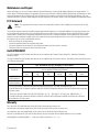


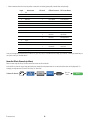
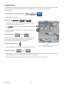

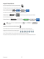
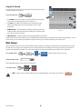
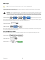
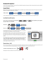

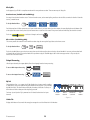
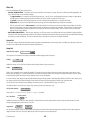

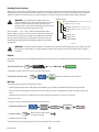

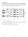
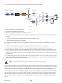
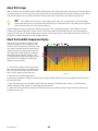
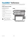
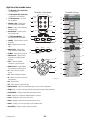
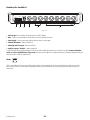


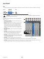

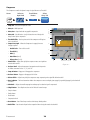
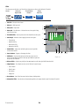


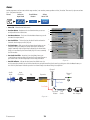
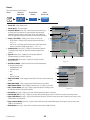
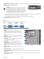
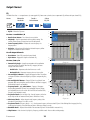
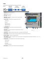
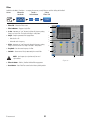
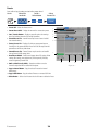
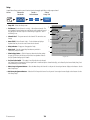
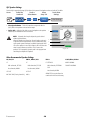
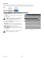

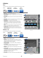

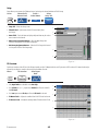
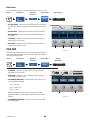
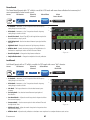

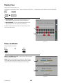


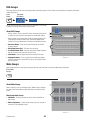
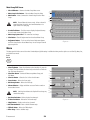
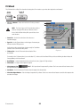

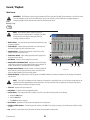
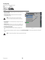
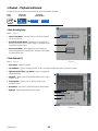
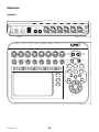


![[Manual Makeup] - inverter & Plc](http://vs1.manualzilla.com/store/data/005906079_1-ccf407c70ed6dc9ae9bfcbd31676317c-150x150.png)