1
True Diversity Receivers
True Diversity Receivers
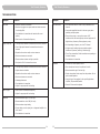
RECEIVER OPERATING TIPS
RACKMOUNT INSTALLATION FOR RECEIVERS
! Prior to powering on the receiver, ensure all transmitters are turned off and the mixer's
volume control is set to a minimized setting. Red LED power indicator is lit when
powered on.
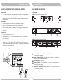
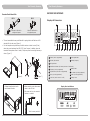
Single half-rack receiver
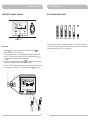
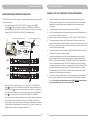
Install provided rack mount kit and fasten with screws on both sides. (Figure 4)
! Normally, the RF meter level glows when a transmitter is powered on to indicate the
receiver is ready for operation. Once an audio signal is received from the transmitter,
the AF meter level glows based on signal strength. If the meter or indicator does not
glow or there is no audio output, the system may not be set up properly. Re-check
that the transmitter is turned on and the receiver and transmitter are on the same
frequency (if not, the transmitter will need to be reset via the ACT function).
! The microphone output level needs to be adjusted at the mixer. There is no need to
adjust output levels at the receiver itself.
! The antenna inputs provide 8-volt DC biased and are designed to work with MIPRO
antenna boosters. If the connecting cable is longer than 10 meters (approx. 30'), it is
advisable to install an antenna booster to ensure optimal reception.
(Figure 4)
! Antenna dividers and receivers must be from the same frequency band.
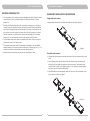
Dual half-rack receivers
Unfasten the top and bottom screws for each receiver. Push the receivers next to each
other.
Place holding plates on top and bottom of the two receivers first, and following the
directions, slide both plates into position over the screw holes. Then tighten screws
(screws should be used in their original location; i.e., top screws for top holding plate
and bottom screws for bottom holding plate).
After both receivers are fixed together, fasten the rack mount kit on both sides of the
joined receivers as shown in Figure 5.
(Figure 5)
8
9