1
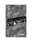
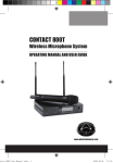
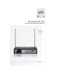
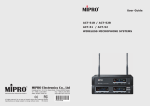
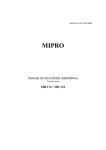
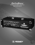
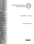
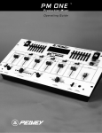
P
C
X
U
3
0
2
PLL True
diversity
UHF
wireless
receiver
OPERATING GUIDE
Intended to alert the user to the presence of uninsulated “dangerous voltage” within
the product’s enclosure that may be of sufficient magnitude to constitute a risk of
electric shock to persons.
Intended to alert the user of the presence of important operating and maintenance
(servicing) instructions in the literature accompanying the product.
CAUTION: Risk of electrical shock — DO NOT OPEN!
CAUTION: To reduce the risk of electric shock, do not remove cover. No user serviceable
parts inside. Refer servicing to qualified service personnel.
WARNING: To prevent electrical shock or fire hazard, do not expose this appliance to rain
or moisture. Before using this appliance, read the operating guide for further warnings.
Este símbolo tiene el propósito, de alertar al usuario de la presencia de “(voltaje)
peligroso” sin aislamiento dentro de la caja del producto y que puede tener una
magnitud suficiente como para constituir riesgo de descarga eléctrica.
Este símbolo tiene el propósito de alertar al usario de la presencia de instruccones
importantes sobre la operación y mantenimiento en la información que viene con el
producto.
PRECAUCION: Riesgo de descarga eléctrica ¡NO ABRIR!
PRECAUCION: Para disminuír el riesgo de descarga eléctrica, no abra la cubierta. No
hay piezas útiles dentro. Deje todo mantenimiento en manos del personal técnico cualificado.
ADVERTENCIA: Para evitar descargas eléctricas o peligro de incendio, no deje expuesto
a la lluvia o humedad este aparato Antes de usar este aparato, Iea más advertencias en
la guía de operación.
Ce symbole est utilisé dans ce manuel pour indiquer à l’utilisateur la présence
d’une tension dangereuse pouvant être d’amplitude suffisante pour constituer un
risque de choc électrique.
Ce symbole est utilisé dans ce manuel pour indiquer à l’utilisateur qu’il ou qu’elle
trouvera d’importantes instructions concernant l’utilisation et l’entretien de l’appareil
dans le paragraphe signalé.
ATTENTION: Risques de choc électrique — NE PAS OUVRIR!
ATTENTION: Afin de réduire le risque de choc électrique, ne pas enlever le couvercle. Il
ne se trouve à l’intérieur aucune pièce pouvant être reparée par l’utilisateur. Confiez
I’entretien et la réparation de l’appareil à un réparateur Peavey agréé.
AVERTISSEMENT: Afin de prévenir les risques de décharge électrique ou de feu,
n’exposez pas cet appareil à la pluie ou à l’humidité. Avant d’utiliser cet appareil, lisez
attentivement les avertissements supplémentaires de ce manuel.
Dieses Symbol soll den Anwender vor unisolierten gefährlichen Spannungen innerhalb des Gehäuses warnen, die von Ausreichender Stärke sind, um einen elektrischen Schlag verursachen zu können.
Dieses Symbol soll den Benutzer auf wichtige Instruktionen in der
Bedienungsanleitung aufmerksam machen, die Handhabung und Wartung des
Produkts betreffen.
VORSICHT: Risiko — Elektrischer Schlag! Nicht öffnen!
VORSICHT: Um das Risiko eines elektrischen Schlages zu vermeiden, nicht die
Abdeckung enfernen. Es befinden sich keine Teile darin, die vom Anwender repariert
werden könnten. Reparaturen nur von qualifiziertem Fachpersonal durchführen lassen.
ACHTUNG: Um einen elektrischen Schlag oder Feuergefahr zu vermeiden, sollte dieses
Gerät nicht dem Regen oder Feuchtigkeit ausgesetzt werden. Vor Inbetriebnahme
unbedingt die Bedienungsanleitung lesen.
2
INTRODUCTION
Thank you for selecting a Peavey Pro Comm PCXU302 quartz controlled single channel true diversity wireless
microphone system. Before operating and installing this
system please read this instruction manual carefully and
thoroughly in order to attain the correct operating
procedures and to achieve the best results.
True Diversity Receiver
The Peavey Pro Comm PCX-U302 quartz controlled
receiver is a true diversity wireless system. This system is
also equipped with “Superior frequency tracking and muting
techniques” that is effective in eliminating the random noise
interference when the receiver is in standby state. The
Peavey Pro Comm PCX-U302 receiver is equipped with
both balanced and unbalanced outputs.
This system includes the following accessories:
•
AC/DC Adapter
•
Mic Clip
•
Antenna (2)
•
Instruction Manual
1.
UNIT FEATURES AND FUNCTIONS
A.
Front Panel
1
2
5
6
3
4
7
Figure 1
3
8
9
10
1.
Antenna Input Connector A
2.
Power Switch and Indicator:
When the switch is turned on the red indicator
illuminates to denote normal power status.
3.
Group Selector:
Selects a group of frequencies.
4.
Channel Selector:
Selects a channel within a group. There are six
group numbers available. Groups one through four
each have six available channels (one through six).
Groups five through six each have three available
channels (one through three). All channels within the
same group are non-interfering when used in multiple
system installations (except group six).
5.
Group Indicator:
Indicates the group selected.
6.
Channel Indicator:
Indicates the channel selected.
7.
RF Signal Level Indicator:
Indicates the RF signal strength received from the
microphone. As soon as the signal is emitted from
the microphone the LED indicator illuminates.
8.
Audio Signal Level Indicator:
Indicates the audio signal level. As soon as the
microphone signal is modulated, the LED indicator
illuminates.
9.
Volume Control:
Adjusts the AF output level of the receiver.
4
10.
Antenna Input Connector B
REAR PANEL
11
12
13
14
15
Figure 2
B. Rear Panel
11.
DC 12V Input Jack:
Connect the 12V DC plug from the AC/DC adapter.
12.
Balanced Audio Output Jack:
XLR type connector
13.
Unbalanced Audio Output Jack:
1/4" Phone Jack
14.
Unbalanced Level Switch:
“LOW” selection is for “Microphone-Level” output.
“HIGH” selection is for “Line-Out” level output.
15.
Squelch Adjustment:
Adjust the squelch level to eliminate the RF noise
interference at the receiver.
2.
INSTALLATION OF THE RECEIVER
1.
Install one of the antennas at the antenna
input connector A. Then install the other
antenna at the antenna input connector B.
Make sure both antennas are in the vertical
position.
5
2.
AC/DC Power Connection:
Fig. 3
Connect the AC/DC adapter cable to the DC 12V
input jack. Then plug the adapter unit into an
appropriate AC outlet as shown in figure 3. Caution:
Make sure the correct voltage is present at the AC
outlet as indicated on the AC/DC adapter.
3.
AUDIO OUTPUT CONNECTION:
a.
Unbalanced Level Switch Setting Position:
Make sure to match the unbalanced output
setting to the device input setting. The
incorrect setting could result in low sensitivity
level or over load distortion. Ex. (If you are
going into the “Line” input on a mixer or
amplifier then the switch should be set to the
high position. If you are going into the “Mic”
input of an amplifier or mixer then the switch
should be set to the low position.)
b.
Unbalanced Output:
Connect the 1/4" phone plug of the audio
cable into the unbalanced output connector on
the back of the receiver. Connect the other
end of the cable to the proper input of the
6
desired device. Make sure the unbalanced
level switch is in the proper position before
applying power.
c.
Balanced Output:
Connect the male XLR connector into the
balanced output connector on the back of the
receiver. Connect the other end of the cable
into the “Mic/Balanced” input of the desired
device. The characteristics of the 3-pin XLR
connector are shown below in figure 4.
GND PIN 1
PIN 2
PIN 3
Fig. 4
7
3.
TWO 19/2-INCH UNITS RECEIVER INSTALLATION
A.
Setup for single half-rack receiver
1.
Push the rack mount brackets (RM-11)
upwards until it is firmly attached to the
receiver. (Figure 5)
Fig. 5
B.
SETUP FOR DUAL HALF-RACK RECEIVERS
1.
Remove the screws at the top and bottom of
the receiver where they will be joined together.
Remove one steel plate from each receiver.
Push the receivers next to each other. Refer
to figure 6.
2.
Insert the steel plate in between the two
receivers (top and bottom). Align and fasten
the screws tightly as shown in figure 6.
3.
Align and fasten the rack mount brackets
(RM-12) on the outer sides of both receivers
as shown in figure 6.
8
Fig. 6
4.
After completion, it can be rackmounted into
an EIA standard rack case. Shown in figure 7.
5.
Make sure that the system performs correctly
by placing the system away from noise
sources. Place the receiver at least one meter
above the ground and one meter away from
noise sources. Place the microphone at least
one meter away from the receiving antenna,
as shown in figure 8.
Fig. 7
Fig. 8
9
4.
OPERATION INSTRUCTIONS
1.
Turn the volume controls of the receiver and
device in use to a minimum setting before
turning on the microphone transmitter. After
the receivers power switch is set to the on
position, the power switch’s red indicator
illuminates to denote normal power status.
2.
If the SIGNAL LED indicators of the receiver
are illuminated before switching on the
microphone or transmitter, it indicates the
receiver is receiving interference signals. The
more LEDs that illuminate the more severity of
interference. This system has “Pilotone” and
“NoiseLock” dual-squelch features so noise
output will not occur. If multiple channels are
used and both SIGNAL and AUDIO LEDs
illuminate before the transmitter is turned on,
simply adjust the Squelch controls clockwise
until the AUDIO signal indicators extinguish.
(Figure 9). However, by adjusting the squelch
controls it affects the sensitivity level of the
receiver, therefore, shortening the operating
distance and decreasing the stability.
Figure 9
3.
Under normal circumstances, the SIGNAL
indicator lights up when a microphone or
transmitter is turned on near the receiver to
indicate the receiver is ready for normal
operation. Once sounds enter into the
microphone the AUDIO LED indicators will
10
illuminate according to the strength of sound
level. If the LEDs do not illuminate or sound is
not present at the output, the system is not
functioning properly and must be checked.
4. RECEIVER AND AMPLIFIER VOLUME ADJUSTMENT:
a.
Unbalanced Audio Output: Switch the level
switch on the rear panel of the receiver to the
left “LOW” Position, then adjust the volume
control to twelve o’clock position. Adjust the
volume control of the amplifier or mixer to an
appropriate sound level. The volume control is
used for fine adjustment of the microphone
sensitivity. When the knob is turned to the
twelve o’clock position the output sensitivity
level of the wireless microphone is the same
as a normal dynamic microphone. Once the
receiver output level is appropriately adjusted,
do not adjust the volume control again. Adjust
the mixer or amplifier volume control if the
sound level needs to increase or decrease.
b.
Balanced Audio Output: Adjust according to
the unbalanced audio output method in the
previous step. (Note: The level switch does
not effect the balanced output.)
c.
To obtain the same sensitivity level when
using a wireless microphone and a wired
microphone with one amplifier or mixer
connect both the receiver output and the wired
output to a “MIC-IN” input jack of the amplifier
or mixer. Adjust the volume controls of the
amplifier or mixer to the same desired level,
then properly fine adjust the receiver volume
control to match the same sensitivity as the
wired microphone.
11
d.
If the receiver output level is adjusted to a
level that is near the maximum input level of
the desired device, it will cause saturation
distortion of the device when the receiver
output level is increased due to a increase in
level by the sound source. Conversely, S/N
ratio will decrease if the receiver volume
control is adjusted too low.
5.
Plug the cable of the mains unit into DC
socket on the receiver’s back panel. Thread
the cable through the cable grip as shown in
the figure below (Figure 10). The cable grip
prevents the connector from being pulled off
by accident.
Fig. 10
5.
Caution
1.
Since the installation of the antenna influences
the operating efficiency of the receiver, the
most important rule is to minimize the distance
as much as possible between the receiving
antenna and the microphone for the best
reception and performance.
2.
The output voltage of the external DC power
supply should not be below 12V, otherwise it
will not work properly. If the voltage is over
15V some components of the receiver will be
damaged due to excessive current draw. Use
a power supply with a 1A minimum rating.
12
SELECTING A FREQUENCY CHANNEL ON THE RECEIVER
Your local dealer/distributor should be able to advise
you on the best frequency selection for your area and help
with selecting combinations of non interfering frequencies
for multi channel installations. Interference is the most
commonly reported “fault” with wireless microphone
systems; we offer thirty channels from which to choose to
help solve the problem. If you are interfered with, please try
changing the group/channel combination before picking up
the phone. Remember a group/channel combination which
works in one venue will not necessarily work in another
venue but the solution could be no more than the turn of a
dial away. Cross frequency interference is not a fault, it is a
merely a symptom of some form of outside interference or
incorrect frequency selection.
Make your choice of group and channel. (Ensure that
the same combination is selected at the transmitter). If a “-”
symbol is displayed, it means that your choice of switch
position has no connection (only thirty of the possible switch
settings are used so there will be some blanks). A two digit,
numeric display is required for an operational group/channel
combination. There are six group numbers available.
Groups one through four each have six available channels,
one through six. Groups five through six each have three
available channels, one through three. All channels within
the same group are non-interfering (except Group six) when
used in multiple system installations. Move through the
groups and channels until you come to a clear combination.
Please take care when changing the switch settings, the
switches are fragile components. Your local dealer/
distributor will be able to help you with advice as to the
specific frequencies represented by the various group/
channel combinations available to you. This information
may be useful, particularly in a multi use venue.
13
HANDHELD WIRELESS MICROPHONE TRANSMITTER
Like the receiver, the hand held microphone features
advanced synthesized PLL design. It is preprogrammed
with 30 user selectable frequencies and incorporates
“Superior frequency tracking and muting techniques” dual
squelch circuitry. The unique soft velvet rubber finish and
overall balance of the microphone offers comfort and
durability for the user.
The strong mechanical design and construction of the
microphone guarantees robust performance and a long
life of general wear and tear.
1.
Unit Features and Functions
5
1
2
3
4
Figure 11
6
1.
2.
3.
4.
Grill/Ball Screen: incorporates a combination
pop/wind filter and protects the microphone
capsule.
Battery compartment: Accepts a standard/
universal 9-volt. Simply unscrew the grill/ball
screen to access this compartment.
Housing/handle: finished in a durable rubber
velvet material for operator comfort.
Battery status indicator: A ‘flash’ at turn on
indicates that the batter is OK. No flash at turn
14
on indicates that the battery is either dead or
not installed. A constant glow indicates a weak
batter that should be replaced.
5.
On-Of switch. Push forward to turn the
transmitter on and slide back to turn the
transmitter off. RF signal is transmitted almost
immediately the switch is turned on (and the
corresponding RF present lamp will glow on
the receiver), setting the receiver in to ‘stand
by’ mode. AF signal is only transmitted when a
RF link is active and the microphone threshold
is opened, i.e. by speech.
6.
Group and channel selector cover: push this
cover down and back as indicated to access
the group and channel selector switches.
7.
Group selector switch: make sure this setting
matches the group selection on the receiver.
(Under group and channel selector cover.)
8.
Channel selector switch: make sure this
setting matches the channel selection on the
receiver. (Under group and channel selector
cover.)
9.
Unavailable setting indicator. This led glows
(when the transmitter has been powered on) if
you select a switch combination that has no
connection. (Under group and channel
selector cover..)
15
2.
BATTERY INSTALLATION
1.
2.
Fig.12
Unscrew the grill/ball screen assembly at the
collar to expose the battery compartment.
2.
Insert the 9-volt battery taking care to observe
the correct polarity. If the polarity is correct,
the battery status indicator lamp will flash
briefly. If no flash is observed, then it is likely
the polarity is incorrect or the battery is dead
flat and needs to be replaced.
3.
Replace the grill/ball screen assembly, taking
care to line up the 3 pins and polarizing lug
with the 3 contractor plates. Screw the grill/ball
screen back in to place, taking care not to
force the turns. The turns should be smooth
and easy. If the grill/ball screen assembly
appears to either not engage, or tries to cross
thread, remove it and check for the correct
alignment of the pins.
OPERATION OF THE HAND HELD TRANSMITTER
When the microphone is switched on, the led indicator will
flash briefly to indicate that the battery is OK and that the
transmitter is powered up. At the receiver, the RF indicator
will illuminate almost immediately to indicate that a RF link
has been established and the AF indicator will illuminate
16
once audio is present. As mentioned previously, the level of
these two indicators will indicate their signal strength at the
receiver. When the microphone is not in use, please switch
it off to conserve the battery
BELT PACK TRANSMITTER
1
2
3
4
5
7
10
8
6
9
Figure 14
Like the receiver, the belt pack transmitter features
advanced synthesized PLL design. It is preprogrammed
with 30 user selectable frequencies and incorporates
Pilotone and Noise Lock dual squelch circuitry. The
transmitter is capable of connection to a variety of input
sources including lapel microphones, headworn
microphones, guitars and other line level output devices.
1.
Audio input connector. This accepts a variety
of input levels and types. Please refer to page
21 for details of the various connections
options available. It is important that the right
17
connection is used. If you are having problems
with a system, this is one of the first places to
look for the solution.
2.
Transmit antenna: 1/4 wave
3.
GT/MT level selector switch: This switch works
in combination with the way you have wired
the input device (as detailed above). Set this
switch in the GT position if you are connecting
to the output of and electric guitar. Set the
switch to the MT position for all other
connections.
4.
Gain control: this control works when the
GT/MT selector switch is in the MT position
only. It provides the user with a small range of
independent system level control. Once set, it
should be left alone to avoid the user causing
self inflicted embarrassment by crossing the
threshold of feedback or reducing the output
to an inaudible level.
5.
Transmitter housing: made from heavy duty
poly-plastic with a discreet low profile and
smooth contoured shape for wearer comfort.
6.
Battery status indicator: A ‘flash’ at turn on
indicates that the batter is OK. No flash at turn
on indicates that the battery is dead or not
installed. A constant glow indicates a weak
battery that should be replaced.
7.
Power switch: turns power to the transmitter
on and off. A RF link (if available) is opened
immediately the transmitter is switched on. An
AF link is established when a suitable audio
18
signal is present at the input (from a lapel
microphone, guitar etc)
8.
9.
2.
Unused status indicator: this illuminates when
the combination of group and channel you
have selected is not connected.
Group selector switch: make sure this setting
matches the group selection on the receiver.
10.
Channel selector switch: make sure this
setting matches the channel selection on the
receiver.
11.
Battery compartment and cover: accepts one
standard 9V battery. (Figure 14)
OPERATION OF THE BELT PACK TRANSMITTER
11
Figure 14
1.
Push ‘down and out’ to open the battery
compartment.
2.
Insert the battery making sure that correct
polarity is observed. Close the battery cover
as shown in figure 15.
19
3.
Select a group/channel combination, making
sure that it matches the combination already
set on the receiver.
4.
Connect your lapel microphone, guitar lead, or
other input. Connection details are as per
figure 15.
5.
Adjust the gain control on the belt pack to the
desired level.
Figure 15
20
1.
AF 4-PIN INPUT CONNECTION METHODS
1. 2-Wire Electret condenser microphone Capsule
2. 3-Wire Electret condenser microphone Capsule
3. Dynamic Microphone
4. Electric Guitar
5. Line-in (Impedance 8KΩ Attenuated 10 dB)
21
SPECIFICATIONS
1. Overall: UHF PCX-U302
1.
2.
3.
4.
5.
6.
7.
8.
9.
10.
Carrier Frequency Range: UHF Band 790~960 MHz
Oscillation Mode: PLL synthesized
Frequency: Pre-programmed 30 switchable frequencies
Stability: + 0.005 %
Max. Deviation: + 56 KHz with level limiting
Dynamic Range: > 119 dB
S/N Ratio: > 100 dB
T.H.D.: < 0.4 %
Squelch: “Superior frequency tracking and muting
techniques” dual-squelch
Frequency Response: 60 Hz~18 KHz + 3 dB
2. Receiver: UHF PCX-U302
1.
2.
3.
4.
5.
6.
7.
8.
9.
Receiving Method: PLL true diversity single-channel
receiving
Sensitivity: 6 dBuV at S/N > 74 dB
Image Rejection: > 62 dB
Spurious Rejection: > 79 dB
Audio Output: can switch between –2 dB/5 K Ω and
-12 dB/600 Ω unbalanced and balanced
Power Supply: 12~15 VDC/1 A
Panel: 19/2-inch, half-rack size
Dimensions (m/m): 210(L) x 175(W) x 44(H)
Weight: Approx. 1.0 Kgs
3. Transmitter: UHF PCX-U302
1.
2.
3.
4.
5.
6.
7.
8.
Mic Element: Condenser Microphone Capsule
Antenna: Built-in
RF Output: 10~50 mW (according to regulation)
Spurious: < -60 dBc
Battery: One 9-Volt Battery
Dimensions (m/m): 49 x 234(L)
Weight: 250 grams (without battery)
20-hour battery life per single 9-volt alkaline
22
TROUBLESHOOTING GUIDE
Symptom
Distance
Possible
Cause
Possible
Solution
No AF signal
and no RF signal
Any
low transmitter
battery voltage
replace battery
No AF signal
and no RF signal
long
out of range
move transmitter
closer to receiver or
obstecles
No AF signal
but normal RF signal
any
microphone or
other input source
check input source
Distortion with no
AF peak indication
any
low transmitter
battery voltage
replace battery
Noise with low AF
signal and normal
RF signal
any
strong RFI
identify source and
eliminate, or change
frequency of wireless
microphone system
Intermittent AF signal
low RF signal
long
out of range
move transmitter and
closer to RCV
Intermittent AF and
RF signals
average
obstructions
in signal path
remove obstructions
or reposition transmitter
and/or RCV
MULITPLE SYSTEM
Symptom
Distance
Possible
Cause
Action
Distortion on two
or more systems without
any
units on same
frequency
change frequencies
Distortion on one
or more systems without
transmittertransmitter short
transmitter + transmitter change frequencies
intermod
Distortion on one
or more systems without
transmittertransmitter short
transmitter + transmitter increase transmitter
intermod
to transmitter distance
transmitter-receiver
short
transmitter +transmitter
receiver intermod
change frequencies
transmitter-rreceiver
short
transmitter +transmitter
receiver intermod
increase transmitter
to receive distance
Distortion on one or more
systems without
AF peak indication
23
NOTES:
24
NOTES:
25
PEAVEY ELECTRONICS CORPORATION LIMITED WARRANTY
Effective Date: July 1, 1998
What This Warranty Covers
Your Peavey Warranty covers defects in material and workmanship in Peavey products purchased and serviced in the
U.S.A. and Canada.
What This Warranty Does Not Cover
The Warranty does not cover: (1) damage caused by accident, misuse, abuse, improper installation or operation, rental,
product modification or neglect; (2) damage occurring during shipment; (3) damage caused by repair or service performed by persons not authorized by Peavey; (4) products on which the serial number has been altered, defaced or
removed; (5) products not purchased from an Authorized Peavey Dealer.
Who This Warranty Protects
This Warranty protects only the original retail purchaser of the product.
How Long This Warranty Lasts
The Warranty begins on the date of purchase by the original retail purchaser. The duration of the Warranty is as follows:
Product Category
Duration
Guitars/Basses, Amplifiers, Pre-Amplifiers, Mixers, Electronic
Crossovers and Equalizers
2 years *(+ 3 years)
Drums
2 years *(+ 1 year)
Enclosures
3 years *(+ 2 years)
Digital Effect Devices and Keyboard and MIDI Controllers
Microphones
1 year *(+ 1 year)
2 years
Speaker Components (incl. speakers, baskets, drivers,
diaphragm replacement kits and passive crossovers)
and all Accessories
1 year
Tubes and Meters
90 days
[*denotes additional warranty period applicable if optional Warranty Registration Card is completed and
returned to Peavey by original retail purchaser within 90 days of purchase.]
What Peavey Will Do
We will repair or replace (at Peavey's discretion) products covered by warranty at no charge for labor or materials. If
the product or component must be shipped to Peavey for warranty service, the consumer must pay initial shipping
charges. If the repairs are covered by warranty, Peavey will pay the return shipping charges.
How To Get Warranty Service
(1) Take the defective item and your sales receipt or other proof of date of purchase to your Authorized Peavey
Dealer or Authorized Peavey Service Center.
OR
(2) Ship the defective item, prepaid, to Peavey Electronics Corporation, International Service Center, 412 Highway 11 &
80 East, Meridian, MS 39301 or Peavey Canada Ltd., 95 Shields Court, Markham, Ontario, Canada L3R 9T5. Include a
detailed description of the problem, together with a copy of your sales receipt or other proof of date of purchase as evidence of warranty coverage. Also provide a complete return address.
Limitation of Implied Warranties
ANY IMPLIED WARRANTIES, INCLUDING WARRANTIES OF MERCHANTABILITY AND FITNESS FOR A PARTICULAR PURPOSE, ARE LIMITED IN DURATION TO THE LENGTH OF THIS WARRANTY.
Some states do not allow limitations on how long an implied warranty lasts, so the above limitation may not
apply to you.
Exclusions of Damages
PEAVEY'S LIABILITY FOR ANY DEFECTIVE PRODUCT IS LIMITED TO THE REPAIR OR REPLACEMENT OF THE
PRODUCT, AT PEAVEY'S OPTION. IF WE ELECT TO REPLACE THE PRODUCT, THE REPLACEMENT MAY BE A
RECONDITIONED UNIT. PEAVEY SHALL NOT BE LIABLE FOR DAMAGES BASED ON INCONVENIENCE, LOSS
OF USE, LOST PROFITS, LOST SAVINGS, DAMAGE TO ANY OTHER EQUIPMENT OR OTHER ITEMS AT THE SITE
OF USE, OR ANY OTHER DAMAGES WHETHER INCIDENTAL, CONSEQUENTIAL OR OTHERWISE, EVEN IF
PEAVEY HAS BEEN ADVISED OF THE POSSIBILITY OF SUCH DAMAGES.
Some states do not allow the exclusion or limitation of incidental or consequential damages, so the above limitation or exclusion may not apply to you.
This Warranty gives you specific legal rights, and you may also have other rights which vary from state to
state.
If you have any questions about this warranty or service received or if you need assistance in locating an Authorized
Service Center, please contact the Peavey International Service Center at (601) 483-5365 / Peavey Canada Ltd. at
(905) 475-2578.
Features and specifications subject to change without notice.
26
IMPORTANT SAFETY INSTRUCTIONS
1.
WARNING: When using electric products, basic cautions should always be followed, including the following:
Read these instructions.
2.
Keep these instructions.
3.
Heed all warnings.
4.
Follow all instructions.
5.
Do not use this apparatus near water. For example, near or in a bathtub, swimming pool, sink, wet basement, etc.
6.
Clean only with a damp cloth.
7.
Do not block any of the ventilation openings. Install in accordance with manufacturer’s instructions. It should not be placed flat against a
wall or placed in a built-in enclosure that will impede the flow of cooling air.
8.
Do not install near any heat sources such as radiators, heat registers, stoves or other apparatus (including amplifiers) that produce heat.
9.
Do not defeat the safety purpose of the polarized or grounding-type plug. A polarized plug has two blades with one wider than the other. A
grounding type plug has two blades and a third grounding plug. The wide blade or third prong is provided for your safety. When the provided plug does not fit into your inlet, consult an electrician for replacement of the obsolete outlet. Never break off the grounding. Write
for our free booklet “Shock Hazard and Grounding”. Connect only to a power supply of the type marked on the unit adjacent to the power
supply cord.
10.
Protect the power cord from being walked on or pinched, particularly at plugs, convenience receptacles, and the point they exit from the
apparatus.
11. Only use attachments/accessories provided by the manufacturer.
12. Use only with a cart, stand, tripod, bracket, or table specified by the manufacturer, or sold with the apparatus. When a cart is used, use caution
when moving the cart/apparatus combination to avoid injury from tip-over.
13. Unplug this apparatus during lightning storms or when unused for long periods of time.
14. Refer all servicing to qualified service personnel. Servicing is required when the apparatus has been damaged in any way, such as powersupply cord or plug is damaged, liquid has been spilled or objects have fallen into the apparatus, the apparatus has been exposed to rain or
moisture, does not operate normally, or has been dropped.
15. If this product is to be mounted in an equipment rack, rear support should be provided.
16. Exposure to extremely high noise levels may cause a permanent hearing loss. Individuals vary considerably in susceptibility to noise-induced
hearing loss, but nearly everyone will lose some hearing if exposed to sufficiently intense noise for a sufficient time. The U.S. Government’s
Occupational and Health Administration (OSHA) has specified the following permissible noise level exposures:
Duration Per Day In Hours
8
6
4
3
2
1 1/2
1
1/2
1/4 or less
Sound Level dBA, Slow Response
90
92
95
97
100
102
105
110
115
According to OSHA, any exposure in excess of the above permissible limits could result in some hearing loss. Ear plugs or protectors to the ear
canals or over the ears must be worn when operating this amplification system in order to prevent a permanent hearing loss, if exposure is in excess
of the limits as set forth above. To ensure against potentially dangerous exposure to high sound pressure levels, it is recommended that all persons
exposed to equipment capable of producing high sound pressure levels such as this amplification system be protected by hearing protectors while
this unit is in operation.
SAVE THESE INSTRUCTIONS!
27
Features and specifications subject to change without notice.
Peavey Electronics Corporations • 711 A Street • Meridian
MS • 39301 • (601) 483-5365 • Fax 486-1278
©2000