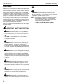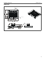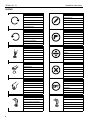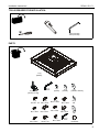
1
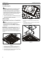
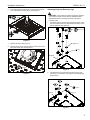
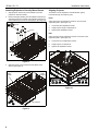
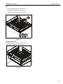
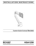
INSTALLATION INSTRUCTIONS
Locking Projector Mount
RPAA1, B1, C1
RPAA1, B1, C1
Installation Instructions
DISCLAIMER
Milestone AV Technologies and its affiliated corporations and
subsidiaries (collectively "Milestone"), intend to make this
manual accurate and complete. However, Milestone makes no
claim that the information contained herein covers all details,
conditions or variations, nor does it provide for every possible
contingency in connection with the installation or use of this
product. The information contained in this document is subject
to change without notice or obligation of any kind. Milestone
makes no representation of warranty, expressed or implied,
regarding the information contained herein. Milestone assumes
no responsibility for accuracy, completeness or sufficiency of
the information contained in this document.
Chief® is a registered trademark of Milestone AV Technologies.
All rights reserved.
IMPORTANT SAFETY INSTRUCTIONS
WARNING: A WARNING alerts you to the possibility of
serious injury or death if you do not follow the instructions.
CAUTION: A CAUTION alerts you to the possibility of
damage or destruction of equipment if you do not follow the
corresponding instructions.
WARNING: Failure to read, thoroughly understand, and
follow all instructions can result in serious personal injury,
damage to equipment, or voiding of factory warranty!
It is the installer’s responsibility to make sure all components
are properly assembled and installed using the instructions
provided.
WARNING: Failure to provide adequate structural strength
for this component can result in serious personal injury or
damage to equipment! It is the installer’s responsibility to
make sure the structure to which this component is attached
can support five times the combined weight of all equipment.
Reinforce the structure as required before installing the
component.
WARNING: Exceeding the weight capacity can result in
serious personal injury or damage to equipment! It is the
installer’s responsibility to make sure the combined weight of
all components attached to the RPAX1 does not exceed 50
lbs (22.68 kg).
WARNING: Use this mounting system only for its intended
use as described in these instructions. Do not use
attachments not recommended by the manufacturer.
WARNING: Never operate this mounting system if it is
damaged. Return the mounting system to a service center for
examination and repair.
2
WARNING: Do not use this product outdoors.
WARNING: The RPAX1 mounts are designed to be
mounted to a 1-1/2" NPT or NPSM following ANSI/ASME
B1.20.1 (Schedule 40, 0.154" minimum thickness aluminumASTM B221) threaded extension column.
NOTE: RPAA1, RPAB1 and RPAC1 models are included in
these installation instructions. Throughout these
instructions "RPAX1" is used to designate all of the
models covered by these instructions.
--SAVE THESE INSTRUCTIONS--
Installation Instructions
RPAA1, B1, C1
DIMENSIONS
27° YAW
ADJUST
12.31
312.7
6.11
155.1
1.50" DIA NPT
4° ROLL
ADJUST
25° PITCH
ADJUST
3.73
94.8
4.02
102.0
3
RPAA1, B1, C1
Installation Instructions
LEGEND
4
Tighten Fastener
Pencil Mark
Apretar elemento de fijación
Marcar con lápiz
Befestigungsteil festziehen
Stiftmarkierung
Apertar fixador
Marcar com lápis
Serrare il fissaggio
Segno a matita
Bevestiging vastdraaien
Potloodmerkteken
Serrez les fixations
Marquage au crayon
Loosen Fastener
Drill Hole
Aflojar elemento de fijación
Perforar
Befestigungsteil lösen
Bohrloch
Desapertar fixador
Fazer furo
Allentare il fissaggio
Praticare un foro
Bevestiging losdraaien
Gat boren
Desserrez les fixations
Percez un trou
Phillips Screwdriver
Adjust
Destornillador Phillips
Ajustar
Kreuzschlitzschraubendreher
Einstellen
Chave de fendas Phillips
Ajustar
Cacciavite a stella
Regolare
Kruiskopschroevendraaier
Afstellen
Tournevis à pointe cruciforme
Ajuster
Open-Ended Wrench
Remove
Llave de boca
Quitar
Gabelschlüssel
Entfernen
Chave de bocas
Remover
Chiave a punte aperte
Rimuovere
Steeksleutel
Verwijderen
Clé à fourche
Retirez
By Hand
Optional
A mano
Opcional
Von Hand
Optional
Com a mão
Opcional
A mano
Opzionale
Met de hand
Optie
À la main
En option
Hex-Head Wrench
Security Wrench
Llave de cabeza hexagonal
Llave de seguridad
Sechskantschlüssel
Sicherheitsschlüssel
Chave de cabeça sextavada
Chave de segurança
Chiave esagonale
Chiave di sicurezza
Zeskantsleutel
Veiligheidssleutel
Clé à tête hexagonale
Clé de sécurité
Installation Instructions
RPAA1, B1, C1
TOOLS REQUIRED FOR INSTALLATION
3/32" (included)
5/32" (included)
PARTS
Q (1)
[RPAX1]
R (4)
[security box leg]
S (1)
5/32"
A (4)
D (4)
#10-24 x 1/4" M5 x 12mm
B (4)
M3 x 10mm
C (4)
M4 x 10mm
E (4)
M6 x 12mm
F (4)
1/4-20 x 1/2"
T (8)
[spacer]
G (4)
M2.5 x 10mm
H (4)
M3 x 10mm
J (4)
M4 x 10mm
U (4)
[washer]
K (4)
M5 x 12mm
L (4)
M6 x 12mm
O (1)
3/32"
V (4)
[adhesive washer]
M (4)
M4
N (4)
M6
P (4)
[thumbnut]
5
RPAA1, B1, C1
Installation Instructions
PREPARATION
Locate Mounting Site
WARNING: IMPROPER INSTALLATION MAY LEAD TO
PROJECTOR MOUNT FALLING CAUSING SEVERE
PERSONAL INJURY OR DAMAGE TO EQUIPMENT! It is
the installers responsibility to make certain the structure to
which the projector mount is being mounted is capable of
supporting five times the weight of the projector mount and all
attached equipment. Reinforce the structure as required
before installing the projector mount.
1.
Determine required position of the RPAX1 projector mount.
2.
Determine required distance of the projector mount from the
screen using the projector specifications.
Security
Screw
3
INSTALLATION
Figure 2
Installing RPAX1 Outer Sleeve to Threaded Pipe
WARNING: IMPROPER INSTALLATION CAN RESULT IN
SERIOUS PERSONAL INJURY OR DAMAGE TO
EQUIPMENT! Structural members MUST be capable of
supporting five times the combined weight of all equipment
being mounted.
4.
Align RPAX1 outer sleeve with end of NTP pipe. (See
Figure 3)
5.
Thread RPAX1 sleeve up onto pipe by turning clockwise
until hand tight. (See Figure 3)
IMPORTANT ! : These installation instructions assume
that a 1-1/2" NPT or NPSM (Schedule 40, 0.154"
minimum thickness aluminum - ASTM B221) threaded
extension column (not included) has been properly
installed (with a minimum of four threads engaged) and is
in place.
1
5
2
4
Figure 3
Figure 1
1.
Install ceiling plate and extension accessories following
installation instruction provided by manufacturer.
2.
Remove drawer from RPAX1 outer sleeve. (See Figure 1)
3.
Loosen security screw on bottom of RPAX1 sleeve until set
screw is fully exposed. (See Figure 2)
6
Installation Instructions
6.
RPAA1, B1, C1
Turn RPAX1 sleeve clockwise or counterclockwise until the
front of the RPAX1 is facing target. (See Figure 4)
Attaching Projector Security Legs
CAUTION: Using screws of improper length may damage
set
screw
7
your projector! Proper screws will have adequate thread
engagement without contacting the bottom of projector
mounting holes.
6
1.
Attach the projector security legs (R) to the projector, using
the correct size screws (A-L) and washers (M or N) for your
specific projector. (See Figure 6)
8
(A-L) x 4
or
Figure 4
7.
Tighten set screw. (See Figure 4)
8.
Tighten security screw until set screw cannot be seen from
set screw access hole. (See Figure 5)
(M) or (N) x 4
(R) x 4
Projector
8
security
screw
Figure 6
Figure 5
2.
Add washers (U) to the projector security legs (R). Add
spacers (T) as necessary to the projector security legs (R).
(See Figure 7)
2 (U) x 4
(T) x 4
(R) x 4
Figure 7
7
RPAA1, B1, C1
Installation Instructions
Attaching Projector to Security Mount Drawer
Aligning Projector
1.
Align projector and security mount drawer so that the
projector is oriented correctly.
The RPAX1 can be adjusted for vertical elevation (pitch),
horizontal tilt (roll), and rotation (yaw).
2.
Remove the paper backing from the adhesive washers (V)
and attach projector to drawer using adhesive washers (V)
and thumbnuts (P) over the security legs (R). (See Figure 8)
Pitch
(P) x 4
2
(V) x 4
Adjust pitch using the adjustment screws on the end of the
adjustment plate. (See Figure 10)
1.
Loosen the pitch adjustment screws.
2.
Adjust projector angle to desired pitch.
3.
Tighten pitch adjustment screws.
Roll
Adjust roll using the two adjustment screws on the back of the
adjustment plate. (See Figure 10)
(R) x 4
4.
Loosen the two roll adjustment screws.
5.
Adjust projector to desired roll.
6.
Tighten roll adjustment screws.
Projector
2
Figure 8
3.
Slide the security mount drawer into the RPAX1 outer
sleeve. (See Figure 9)
Security
Mount
Drawer
5
RPAX1
Outer
Sleeve
4
5
1
6
Figure 10
Projector
3
Figure 9
8
2
3
pitch adjustment screws
roll adjustment screws
Installation Instructions
RPAA1, B1, C1
Yaw
1.
Loosen yaw adjustment screw. (See Figure 11)
2.
Adjust mount to desired yaw. (See Figure 11)
3.
Tighten yaw adjustment screw. (See Figure 11)
2
1
2
3
Figure 11
Locking the RPAX1
After all installation and adjustment steps have been
completed, lock the RPAX1. (See Figure 12)
RPAX1
Lock
Figure 12
9
RPAA1, B1, C1
10
Installation Instructions
Installation Instructions
RPAA1, B1, C1
11
RPAA1, B1, C1
Installation Instructions
USA/International
Europe
Chief Manufacturing, a products division
of Milestone AV Technologies
8802-000253 Rev01
2012 Milestone AV Technologies, a
Duchossois Group Company
www.chiefmfg.com
02/12
Asia Pacific
A
P
F
A
P
F
A
6436 City West Parkway, Eden Prairie, MN 55344
800.582.6480 / 952.225.6000
877.894.6918 / 952.894.6918
Franklinstraat 14, 6003 DK Weert, Netherlands
+31 (0) 495 580 852
+31 (0) 495 580 845
Office No. 1 on 12/F, Shatin Galleria
18-24 Shan Mei Street
Fotan, Shatin, Hong Kong
P 852 2145 4099
F 852 2145 4477