1
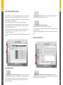
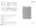
QUICK START GUIDE
Arcticroc 4-bay RAID System
with LCM Panel
®
Time Machine
Compatible
FireWire
Windows 2000
®
to Windows 8
Compatible
USB
2.0
HI-SPEED
USB
3.0
SUPER-SPEED
3 Gbits/sec
EN
EN
Contents
Package Content ....................................................................................
03
Front View .............................................................................................
04
Top View ................................................................................................
04
Rear View ..............................................................................................
04
Installing The RAID System ....................................................................
05
RAID Configuration ................................................................................
08
With LCM Operation ...............................................................
08
LCM Basic Menu .....................................................................
08
With RAID MASTER Operation ................................................
11
Basic Mode Menu .................................................................... 11
Advance Mode Menu .............................................................. 12
Number of Disks Supporting Each RAID Mode ...................................... 13
LED Indicators ........................................................................................ 14
Power LED x 1 .......................................................................... 14
RAID Alert LED x 1 ...................................................................
14
HDD LED x 8 ............................................................................. 14
01
02
EN
EN
This Arcticroc 4-bay RAID System with LCM panel and RAID
MASTER (Graphic User Interface) provides massive storage
capacity and advanced RAID configuration options with RAID 0,
RAID 1, Span, Clone, RAID 5, RAID 1+1, and optional HotSpare
in a desktop storage device.
Front View
The installation instructions in this manual apply to the following models:
• SATA-eSATA/USB 2.0/FireWire 400/FireWire 800 combo
Top View
Package Content
Please check all Package Contents when opening it.
SATA-eSATA/USB 2.0 Combo/FireWire 400/FireWire 800 Combo
4-bay RAID
4 spare HDD screws
provided on back
part of cover lid
03
FireWire 400
4 handles
FireWire 800
HDD
screws
x 16
External Power
Supply
CD and
USB Type
Quick
B to A
Installation
Cable
Guide
Rear View
eSATA
cable
04
EN
EN
Installing The RAID System
To assemble the RAID System, please follow the
steps listed in the instructions below:
05
1
Place the RAID System with its Front View
facing you. Push the lid in the direction
away from you, front to back, using your
thumbs.
2
Take out the handles from the RAID
System itself and locate the HDD screws in
the packaging box
3
Position the handle to the HDD end,
which is facing away from the interface
connectors, and align it with the screw
hole openings.
4
Fasten the handle onto the HDD by
inserting and tightening the screws on
both ends of the handle.
5
Finally, test slide the handle to make sure
that the holes glide smoothly on the
screw guides. Repeat the same
procedures for the rest of HDDs.
6
Fasten the handle onto the HDD by
inserting and lightening the screws on
both ends of the handle.
7
Place RAID System with its Front View
facing you and the top lid on. Push the lid
firmly downward and toward you, back to
front.
8
Connect the AC/DC power adapter.
06
EN
EN
RAID Configuration
9
Insert both ends of the USB 2.0 cable (or
eSATA, FireWire 400, FireWire 800) into
the corresponding port of the RAID
system and the host.
With LCM operation
The LCM on the SMART RAID System will display basic information for the
inserted HDDs, RAID System itself, and basic RAID function operations.
Please use the LCM buttons to operate.
LCM Basic Menu
1. Quick Setup: Enables general basic set up functions.
10 Turn the power switch to the “on” position.
• Create One RAID: To assign and create the RAID System’s inserted HDDs
into a preferred RAID Mode. Also to set up a RAID Mode Password for this
particular RAID mode’s HDDs.
• Delete All RAID: To delete the current RAID mode setup in the RAID
System’s inserted HDDs.
2. Disk Manager: Provides basic information of specified HDD.
11 When connected, the Power LED light will
become steadily green, and the HDD LED
lights will become white and blink about
15 seconds.
• Select Disk: To retrieve detailed information regarding the selected disk
such as model, serial number, firmware version, total capacity, unused
capacity available, and disk status.
3. System Manager: Supplies basic RAID System information, password
and access capabilities.
• System Info: To retrieve detailed information regarding the RAID System
such as firmware version and control number.
• Change Password: To set up or change the password for access to the LCM
operations only. This is not the same as the RAID Mode password set up via
the RAID MASTER and LCM (Create One RAID).
• Logout From Menu: To esc or exit from the menu.
12 You are now ready to begin using your
RAID system!
07
08
EN
EN
3. Use the Up ( ) and Down ( ) Buttons to select which RAID Mode to use.
Initializing
Rocstor
Main Menu
Quick Setup
Main Menu
Disk Manager
Main Menu
System Manager
4. Enter the ‘password’.
Disk Manager
Select: Disk 1
Quick Setup:
Create One RAID
Quick Setup:
Delete All RAID
System Manager:
Systm Info.
System Manager:
Change Password
System Manager:
Logout From Menu
For more information about the LCM Process Tree, please go to the user
manual in the provided CD.
If you wish to assign and create the RAID using the LCM only, please follow
the steps listed in the instructions provided below:
1. Turn ‘On’ the RAID System. Under Main Menu, press Down Button ( )
to select ‘Quick Setup’ and press Enter ( )
2. Select ‘Create One RAID’ and press Enter ( ).
09
5. After verifying the ‘password’, it will display “Are You Sure? Enter: Yes Esc:
No”. Press Enter ( ) to confirm or Esc ( x ) to cancel.
6. The, the RAID System will begin processing the preferred RAID Mode and
display “Waiting System Re-initialize…”. Once completed, the RAUD System
is ready for usage under the chosen RAID Mode!
10
EN
EN
With RAID MASTER Operation
The RAID MASTER is a newly-designed GUI Software for our 4-bay SMART
RAID System. The drivers of the RAID MASTER for both PC and MAC ate
provided via CD or our website. It provides a more convenient yet modern
way to manage your RAID System.
Please follow the steps listed in the instructions provided below:
1. If using the installation CD, please copy the driver for MAC or PC to your
desktop. Double click the driver to decompress. Then, open the folder
stating “RAID MASTER_vx.xx.xx”.
2. Once opened: For MAC, please double click on the “RAID MASTER” to
open the program. For PC, please double click on the icon stating
“Setup.exe” to begin set up.
3. Once the installation is completed, the RAID MASTER Menu page should
appear.
2.
Event Log: Records all process completed for the RAID
System and can be saved to a text format file.
3.
Basic RAID Configuration:
• Provides the basic RAID Mode setup and configuration.
• Give a place to insert and apply a password to protect any changes done
on the RAID System.
• Shows what type of RAID Mode is setup at the moment for the inserted
HDDs.
Advance Mode Menu
Basic Mode Menu
11
1.
RAID and Disk Information: Provides the basic information for the RAID System itself once the RAID System is connected to the
host. For example, the Controller information, serial number for each
inserted HDDs, what kind of RAID format is assigned for each inserted
HDDs, and much more.
1.
Email Notification & Event Settings: Available Email
Notification (such as events of errors, alert, and change of the RAID System)
and Event Settings based on preference.
12
EN
EN
LED Indicator
2.
Advanced RAID Configuration: Similar to Basic RAID
configuration with additional options.
• Select which HDDs and their storage capacities.
• Perform a combination of RAID Modes at same time. For example,
creating two sets of RAID 1 or have a combination set of RAID 0 and RAID 1.
• Assign an additional HDD as the Spare to perform Automatic Rebuild
when one of the HDD already in a RAID Mode setup fails (for RAID 1,
CLONE, and RAID 5 only.)
3.
Firmware Information: Provides Controller’s firmware
information such as product name, firmware version, manufacturer, and
flash number. Also, gives and option to update the firmware when
necessary.
4.
RAID Settings: Allow set up of RAID Standby Timer
Settings and RAID Rebuild Priority Settings based on preference.
For more information about the RAID Master operation, please go to the
user manual in the provided CD.
Power LED x 1
RAID Alert LED x 1
Indicators
Color
Indicators
Color
Power on
Green
Healthy
None
Power off
None
Rebuild
Blink Red
Broken
Red
Degrade
Red
Fan Error
Red
HDD LED x 8
HDD (1, 2, 3, 4)
Indicator
Left
Right
(Connection/Acess)
(Health)
RAID Mode
Disk not detected
None
None
All Modes
Disk detected
White
None
All Modes
Disk not healthy
White
Red
All Modes
Data access
Flash White
None
All Modes
Source HDD
Disk
Target HDD
Rebuild
RAID Alert
Flash White
None
Flash White
Red Blink
Blink Red
RID 1, RAID 5,
RAID 1+0,
Clone
Number of Disks Supporting Each RAID Mode
13
RAID Modes
Number of Disk in RAID
RAID 0 (Striping)
2 to 4
RAID 1 (Mirroring)
2
Span
2 to 4
Clone
2 to 4
RAID 5
3 or 4
RAID 1+0
4
JBOD
1 to 4
14