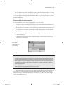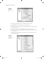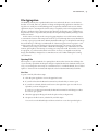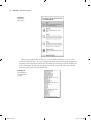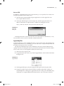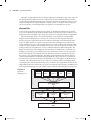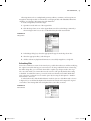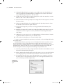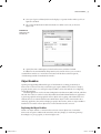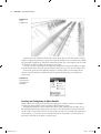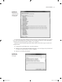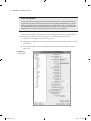
1
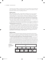
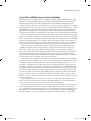
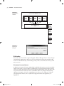
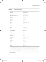
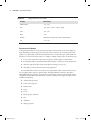
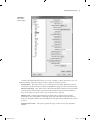
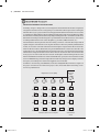
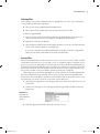
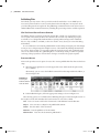
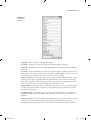
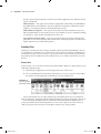
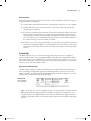
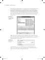
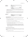
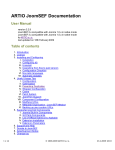
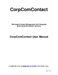
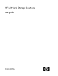
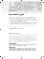
Chapter 2 Files and File Types Chapter 1, “Getting to Know Autodesk Navisworks,” introduced you to the basics of the Autodesk Navisworks interface. In this chapter, we’ll cover the principles of the various file types and the process of aggregating these disparate files together to create a single whole-project view of your model. By bringing together geometry and data from multidisciplinary teams, you can explore and review complex models in real time. One of the most important things you can do to become proficient at Navisworks is get a firm grasp on file types and the process of how they are aggregated. File aggregation is one of the core strengths of Navisworks and one that is the foundation for all the features you’ll discover in the following chapters. After all, this is how you bring your project together. Spend some time with these concepts and you’ll be far more successful! In this chapter, you’ll learn to: •u Understand Navisworks file formats •u Open and append various files •u Configure object enablers Navisworks File Types The power of Navisworks rests in its ability to open files originated from a variety of design and engineering applications and its capacity to then share and coordinate these different file types into a single data-rich intelligent model. The composite model of aggregated files can then be selectively available or viewed by all parties involved to enhance the design review and coordination process. In addition, Navisworks converts and compresses most files up to 80 percent of their original size, so sharing and collaborating is greatly improved. This section will cover the numerous file types and explain the differences. We will also explore some of the standard workflows and provide best practices for file sharing and aggregation. Native File Formats Navisworks utilizes three native file formats: NWD, NWC, and NWF. This section will explain the differences and explore some of the various workflows. NWD File Format An NWD, or Navisworks Document file, is the basic file format that contains all geometry, relevant object properties, and clash tests, as well as any markup, comments, and viewpoint information. As the project evolves, an NWD can be thought of as a snapshot of the model that 006788c02.indd 31 6/23/11 1:47:35 AM 32 | Chapter 2 Files and File Types captures the current conditions or milestone events. This also includes clash tests and 4D simulations, which will be covered in subsequent chapters. The file size of most NWDs is considerably smaller compared to the corresponding CAD format. NWC File Format NWC, or Navisworks Cache files, are generated when CAD files or laser scans are opened, merged, or appended in Navisworks. They can also be created by using a designated file exporter, which we’ll cover later in the section “File Exporters.” NWC files are read-only files and can be thought of as a transfer mechanism to convert CAD, Autodesk Revit, and other model data into a format that Navisworks recognizes. All geometry, relevant object property information, and display settings from the original source files will carry over with the NWC export. Once the file is opened in Navisworks, any changes made—such as redlines, markups, viewpoints, or display overrides—cannot be saved back to this format. When the native CAD format file is first brought in, Navisworks creates a file with the same name but with the .nwc file extension in the same directory as the original source file. This is an important concept of a successful Navisworks project, so keep in mind that good model management skills make this process easier. When NWC files are opened, merged, or appended, Navisworks compares the original data to the newly created NWC file and re-caches the file if data in the original file is newer than the NWC. This ensures that as changes are made to the project design, they are reflected in your Navisworks project. If no changes are detected, Navisworks opens from the original NWC file, resulting in quicker loading. As a best practice, consider standardizing on using the Append command instead of Open. Doing so reinforces this concept of file aggregation, which is an important part of the overall project coordination process. NWF File Format NWF files host no 3D geometry but rather contain links to the geometry from the original native source files (see Figure 2.1). Besides the links, NWF files contain such items as markup data, viewpoints, comments, graphical overrides, search/selection sets, TimeLiner, and Clash Detective data. We’ll explore these topics in more detail in future chapters. When working with the NWF file format, you’ll notice the file size for NWFs is extremely small as compared to the NWC/NWD formats; however, remember the user must have access to the original source files to view properly. As you work toward mastery of Navisworks, consider using the NWF as the standard file format during your project. While NWD files can be thought of static snapshots that capture specific milestones, using the NWF workflow is dynamic and allows for easy updating of design changes from the original source files. Later in the book, you’ll explore clash detection, 4D simulation, and other concepts, so having a good grasp of the file formats is crucial. Figure 2.1 NWF Source files linked to the NWF file format NWD DWG/NWC DGN/NWC Laser Scan/ NWC ............ Original Source Data Files 006788c02.indd 32 6/23/11 1:47:36 AM | Navisworks File Types 33 Using NWF and NWD Formats in a Typical Workflow Typical Navisworks workflows utilize a combination of NWD, NWC, and NWF files. As a best practice, it’s recommended that during an ongoing project the NWF file format be utilized so that the original source files can be updated and re-cached. Remember, the NWF format is strictly a container that links out to the different source files. Graphical overrides such as changing model element colors and transparency are captured and stored in the NWF file. As a result, when updated cache files are loaded, Navisworks will remember your graphical settings and apply them to the updated files. This principle is similar to the concept of external references (Xrefs) in AutoCAD whereas changes made to the original source files will update the NWF file. Similar to the NWC format, the NWD format includes all geometry and object property data but can save changes and graphical overrides to the model. The primary difference is that NWD files do not update or re-cache if changes have been made to the original source data. Sometimes having a static representation of your model is useful if you need to archive specific milestone events. Also, since this format has all of the geometry “baked” into the file, it is a perfect format to share with other users without worrying about supplying the accompanying source files. Now that we’ve covered the basic file formats, let’s look at a typical workflow. The project coordinator opens Navisworks and appends the original source 3D data files from the specific trades on the project (e.g., Architecture, MEP, Structure, Civil, or Existing Conditions). Navisworks converts these files to the NWC format and places the NWC files in the same directory as the original source files. Note that certain files types such as Revit (RVT) cannot be appended directly in Navisworks but must be converted to an NWC file first. This concept will be covered in the section “File Exporters” later in this chapter. When the project coordinator saves the Navisworks session, the project is saved as an NWF format, which captures the link to the saved source and NWC files. In the meantime, the architect, MEP coordinator, structural engineer, and civil engineer all make changes, such as moving objects or adding/removing components, to their original 3D data files. When the project coordinator opens the project saved as an NWF, Navisworks will look for the linked files and do a quick comparison to determine if any of the original 3D data files are newer than the NWC files. In our sample workflow, all of these original data sources were modified, so Navisworks re-caches those files and overwrites the original NWC files with the new data. Periodically the project coordinator will save or publish the model to the NWD file format to archive specific milestone events or share with external users who do not have access to the original source data files (see Figure 2.2). In the event the original source files are renamed or moved, Navisworks prompts you for their location, as shown in Figure 2.3. If the accompanying NWC files are moved or deleted, Navisworks automatically re-caches the files and creates a new NWC file. To manually locate the original data source files, click the Browse button and navigate to the new location. When the NWF file is resaved, it will remember the new location for these files. Also, it should be noted that Navisworks uses a relative path structure when saving files. If your project folder contains several subfolders for the various disciplines (Architect, MEP Engineer, Structural Engineer, etc.), you can share this project folder without breaking any of the links. 006788c02.indd 33 6/23/11 1:47:36 AM 34 | Chapter 2 Files and File Types Figure 2.2 Original Source Data files opened in Navisworks and converted to NWC file format Typical project workflow Navisworks Project Folder Architecture (Revit, NWC) MEP (DWG/ NWC) Structure (DWG/ NWC) Civil (DWG/ NWC) Master Navisworks File (NWF) Existing (Scan file/ NWC) Published NWD 8/13/10 Published NWD 8/6/10 Published NWD 7/30/10 Published NWD 7/23/10 Figure 2.3 The Resolve dialog box File Readers File readers allow Navisworks to open and append additional file types from a variety of design and engineering applications. When you open a 3D model in Navisworks, the appropriate file reader is loaded automatically and all model geometry and associated metadata is incorporated into your scene. Navisworks Supported Formats In addition to the native file formats (NWD, NWC, and NWF), Navisworks can read over 40 different 3D CAD formats, as shown in Table 2.1. Model entities contained in both 2D and 3D geometry and all associated object property data is typically supported. Being able to work with such a wide range of file formats allows Navisworks to accommodate almost every design and engineering application. Having this level of file compatibility in turn allows you to collaborate, coordinate, and communicate effectively. For a complete list of supported formats and applications, see Appendix B. 006788c02.indd 34 6/23/11 1:47:36 AM | Navisworks File Types 35 Table 2.1: Supported CAD formats Format Extensions Navisworks .nwd, .nwf, .nwc AutoCAD .dwg, .dwf MicroStation (SE, J, V8, XM) .dgn, .prp, .prw 3D Studio .3ds, .prj ACIS SAT .sat, .sab CIS/2 .stp DWF .dwf, .dwfx, .w2d FBX .fbx IFC .ifc IGES .igs, .iges Inventor .ipt, .iam, .ipj Informatix MAN .man, .cv7 JT Open .jt PDS Design Review .dri Parasolids .x_b Pro/ENGINEER .prt, .asm, .g, .neu RVM .rvm SketchUp .skp STEP .stp, .step STL .stl VRML .wrl, .wrz In addition to the CAD formats, Navisworks is a powerful tool for viewing laser scan files, sometimes referred to as point clouds. These files are made up of millions, even billions of geo-referenced points that typically define the surface of an object. The benefit is that existing conditions such as older building structures or civil site plans can now be captured easily and displayed inside Navisworks to compare against proposed designs. Table 2.2 lists the supported laser scan formats. 006788c02.indd 35 6/23/11 1:47:37 AM 36 | Chapter 2 Files and File Types Table 2.2: Supported laser scan formats Format Extensions ASCII laser file .asc, .txt Faro .fls, .fws, .iQscan, .iQmod, .iQwsp Leica .pts, .ptx Riegl .3dd Trimble Native file not supported; convert to ASCII laser file Z+F .zfc, .zfs Configuring File Readers Configuring file readers is mostly automatic, but there are times when you need to adjust settings depending on the file type. Navisworks provides a full menu for each native file reader. Options vary depending on the file utilized, but the more common file types (DWG/DXF and DGN) have a robust menu with options to configure visibility settings. Here are the basic steps: 1. To access the native file reader’s menu, navigate to Global Options File Readers. 2. In the Options Editor, expand the File Readers hierarchy on the left, as shown in Figure 2.4. 3. Select the appropriate file reader and modify the settings as necessary. 4. Click OK to return to the main Navisworks application. Since the DWG file format is one of the most recognized file reader formats in Navisworks, let’s investigate these options in greater detail. The DWG/DXF file reader uses Autodesk’s ObjectDBX technology, which is guaranteed to read all object geometry and information from all applications that utilize this framework. A partial snapshot of the supported object entities includes the following: •u All 2D and 3D geometry •u Points and snap points •u Named views •u Layers •u Colors •u Blocks, groups, and Xrefs •u Text •u Attributes •u Object properties 006788c02.indd 36 6/23/11 1:47:37 AM | Navisworks File Types 37 Figure 2.4 File reader’s Options Editor Looking at the DWG/DXG file reader, you can see a number of options that allow you to configure the settings of this file reader. Let’s take a deeper look at these options: Faceting Factor This option allows you to control the level of faceting. The default value is 1. Greater values produce smoother results, but add additional polygons and increase the file size. Max Facet Deviation This option controls the maximum distance between the facet and the actual geometry. If the distance is greater than the specified value, Navisworks adds more facets to meet this value. If the value is set to 0, this function is ignored. Split By Color Certain compound objects are displayed as one entity in Navisworks. Checking this box will split these compound objects into individual components based on their color. Examples include a door assembly that can be split into the individual door frame and door. Default Decimal Units This option specifies the type of units used to open the DWG/ DXF file. 006788c02.indd 37 6/23/11 1:47:37 AM 38 | Chapter 2 Files and File Types Merge 3D Faces Occasionally some 3D models will have adjoining faces that consist of the same color, layer, and parent. This option allows Navisworks to interpret those faces as a single object. Line Processing When converting lines and polylines, Navisworks provides three options for processing them: Merge Lines By Color Navisworks will merge any lines on the same layer or proxy entity that contain the same color. This option is useful as it helps speed up navigation and overall conversion. This option is checked by default. As Provided With this option, no additional conversion takes place. All lines and polyline elements are displayed as they are specified in their native DWG file. Separate All Lines Use this option if you want to split all line elements into their respective nodes for each segment of the line. Convert Off This option allows Navisworks to convert certain layers that are switched off in the DWG file. When checked, any file that contains hidden layers will be marked as hidden in Navisworks. Convert Frozen Keeping this option checked will convert layers that are frozen in the DWG file. Any file that contains frozen layers will be marked as hidden in Navisworks when open or appended. Convert Entity Handles Keeping entity handles is an important aspect of object selection. This option will attach entity handle information to the object properties in your Navisworks model. Convert Groups This option allows you to retain your group settings in the DWG file. Files that have this option enabled gain an additional selection level in the selection tree. Convert Xrefs For those who want a seamless opening/appending of their DWG file with all Xrefs, this feature allows you to convert all reference files automatically. If left unchecked, you need to append the files manually. Merge Xrefs Layers This option allows you to merge the layers in an Xref file with the main DWG file in the selection tree. Convert Views Keep this option checked if you want to convert your named views in AutoCAD to viewpoints in Navisworks. Convert Points This option will convert all points in your DWG file. Convert Lines Select this option to convert lines and arcs in your DWG file. Convert Snap Points This option will convert snap points in your DWG file. Convert Text As its name implies, this option will convert text in your DWG file. Default Font This option allows you to define which font you want to use for the converted text. There is no predefined list for this option; rather, you need to type in the name of the font you wish to use. Convert Point Clouds DWG files that have embedded point clouds entities will only display if this box is checked. This option is separate from the laser scan/point cloud readers. Point Cloud Detail This option allows you to specify the density of the point cloud. Values are between 1 and 100, where 100 is the maximum density. To assist with performance issues 006788c02.indd 38 6/23/11 1:47:37 AM | Navisworks File Types 39 when working with larger point clouds, you might want to reduce this value to speed the conversion process. Use Point Cloud Colors Certain point clouds contain native color coding of points. Unchecking this box will ignore these colors and default to the color profile specified in AutoCAD. DWG Loader Version When working with DWG files that utilize ObjectDBX, this option allows you to specify which version to use when loading files. This feature is useful when configuring certain DWG object enablers. You’ll learn more later in this chapter in the section “Object Enablers.” Load Material Definitions Select this option to extract material definitions from DWG files. Use ADT Standard Configuration This option converts geometry and materials in your DWG file using the standard display configuration. Convert Hidden ADT Spaces In certain modeling conventions, objects such as floors or ceilings may be drawn without proper thickness and thus lack any true visible 3D geometry. Select this option to display the hidden geometry. Material Search Paths When files with applied materials are opened or appended in Navisworks, the application will search for all material paths automatically. If additional materials are defined, you can manually specify the path in this field. Be sure to use a semicolon to separate the paths. Render Type These options define how the DWG file is displayed in Navisworks: Automatic This option is selected by default and will read the DWG file with the settings that were saved in the DWG file. Rendered, Shaded, or Wireframe Use these options to override the original settings in your DWG file if the file is not displaying correctly. We recommend that you save your DWG file with the proper display settings to avoid having to manually override these settings. File Exporters File exporters allow you to create native Navisworks NWC files directly from your original source data files for applications that aren’t read natively in Navisworks. This section will explain why you need a file exporter, where to locate these, and the typical workflow to export NWC files to Navisworks. Why You Need a File Exporter Certain file types such as Revit (RVT), 3ds Max (MAX), and ArchiCAD (PLN, PLA) are not recognized by Navisworks in their native format. Navisworks also installs file exporters for AutoCAD-based applications in addition to natively reading the DWG file format. When Navisworks is initially installed, it searches throughout your computer and identifies all compatible design and engineering applications. If a valid installation is detected, it installs the appropriate file exporter for that application. Since the file formats for most applications are unique, most file exporters are product- and release year–specific, so you may have multiple file exporters for the same product family. An example of this is having a Revit file exporter for the 2010 release in addition to one for the 2011 release. 006788c02.indd 39 6/23/11 1:47:38 AM 40 | Chapter 2 Files and File Types For users who do not have access to Navisworks, another option to consider is the NWC File Export Utility (a separate download), which converts the model geometry and any relevant object intelligence into the NWC file format for Navisworks to display. File exporters are also useful for individuals who want to publish their content to the smaller NWC file format for ease in sharing and collaborating. Furthermore, certain CAD applications have custom objects and external referenced files which if not shared or configured properly can lead to missing geometry in your Navisworks model display. The NWC File Export Utility removes all of these barriers and creates an easy and effective way to share your model data with other Navisworks users. Locating and Installing File Exporters When a new application is installed after the original Navisworks installation, the file exporters for that application will need to be reinstalled. They can easily be added afterward in a few simple steps. Let’s explore: 1. Depending on what operating system you’re using, go to your Control Panel and select Add/Remove Software or Uninstall/Change Program. 2. Select Autodesk Navisworks 2012 32-bit Exporter Plug-ins or Autodesk Navisworks 2012 64-bit Exporter Plug-ins from the list. If you’re running a 64-bit OS, you may have both. 3. Double-click on the appropriate file exporter. 4. In the Navisworks Exporter dialog box, select Add Or Remove Features. 5. Select the appropriate application to install an exporter, as shown in Figure 2.5. 6. Click Update. Navisworks will install the new exporters for the selected applications. 7. Select Finish to close the Exporter dialog box. In addition to these steps, you can use the Repair or Reinstall functions from the main Navisworks Exporter dialog box to install the file exporters. When you’re reinstalling Navisworks, it may take longer than the Repair feature. Figure 2.5 Navisworks Exporter list 006788c02.indd 40 6/23/11 1:47:38 AM | Navisworks File Types 41 For users without Navisworks, Autodesk provides the NWC File Export Utility free of charge for all users. You can download it from the Autodesk website at www.autodesk.com/navisworks. Once you’ve downloaded and installed the EXE file, follow all onscreen instructions to complete the installation process. This process will install the NWC File Export Utility on all relevant installed applications. Exporting NWC Files from Source Files To export NWC files from Revit-based applications, follow these steps: 1. In Revit, navigate to the Add-ins tab and select Navisworks 2012 from the External Tools panel (Figure 2.6). 2. In Export Scene As dialog box, specify the filename and select the desired storage location. 3. To adjust the export settings, select the Navisworks Settings button at the bottom of the Export Scene As dialog box. 4. In the Navisworks Options Editor, expand the File Readers hierarchy and select Revit, as shown in Figure 2.7. 5. Adjust the settings and click OK to accept the changes or click Cancel to return to the Export Scene As dialog box. Figure 2.6 Choose Navisworks 2012 from the External Tools panel in Revit. Exporter Not Functioning? If the Export button for the Navisworks exporter is not displayed properly in the Add-ins tab, check to make sure the NWC File Export Utility is installed correctly. For an unavailable (grayed-out) button, make sure you have exited from all active commands in Revit. Also, make sure you’re in a 3D model view. The export feature will not work when you’re viewing schedules, quantities, or other nongraphical data. If you installed any AutoCAD-based application after installing the NWC File Export Utility, you need to update the exporter plug-ins to reflect these changes. To export NWC files from AutoCAD-based applications, the NWC File Export Utility installs ARX plug-ins for any AutoCAD-based product such as AutoCAD Civil 3D, AutoCAD MEP, AutoCAD Plant 3D, or AutoCAD Architecture. This utility is available for any AutoCAD platform from the 2004 release on. 006788c02.indd 41 6/23/11 1:47:38 AM 42 | Chapter 2 Files and File Types Figure 2.7 Navisworks Options Editor for Revit To use the AutoCAD command line to export NWC files, follow these steps: 1. Type NWCOUT in the command line of your AutoCAD model. 2. In the Export To Navisworks dialog box, specify the filename, select the desired storage location, and click Save. 3. To adjust the export settings, type NWOPT at the command line in AutoCAD. 4. In the Navisworks Options Editor, expand the File Readers hierarchy and select DWG, as shown in Figure 2.8. 5. Adjust the settings and click OK to accept the changes or click Cancel to return to the AutoCAD main window. Figure 2.8 Navisworks Options Editor for AutoCAD 006788c02.indd 42 6/23/11 1:47:38 AM | File Aggregation 43 File Aggregation The building industry has expanded and become more technically diverse over the last few decades. As a result, there are a plethora of design and engineering applications aimed at solving their own small piece of the building puzzle. Couple that with the fact that each of these applications has its own unique file format and you can quickly see how managing these files becomes a challenge. This is where Navisworks shines by allowing the user to combine these disparate files into a composite model, thereby removing the interoperability challenges of the numerous formats. In this section, we’ll explore the concept of aggregating these various file formats and ways to automate the creation of the composite model. As you read through this section, think about a current, or past, project and start to identify the different file types or disciplines that make up the model. Doing so will help you understand all of the moving pieces in most projects—and will also make the exercises much more relevant and speed up your mastery of Navisworks. Whether you’re using a native NWC or NWD file or bringing in one of the numerous CAD formats, opening files is the first step to creating your composite model. Navisworks is an intuitive program, so you’ll notice that there is more than one way to accomplish most tasks. By design, this flexibility is designed to accommodate most users’ habits and keep the learning curve minimal. Opening Files We’ll explore a couple of methods for opening files in Navisworks. Navisworks will keep a list of your recently opened files in the Open dialog box. By default this list is limited to 4 files; however, you can change this amount up to a maximum of 16. To override the default, choose Global Options General Environment and adjust the value for Maximum Recently Used Files. New Files To open a new file, follow these steps: 1. Click the green application icon in the upper-left corner. 2. If your file is listed in the Recent Documents list, select the file you want to open. 3. If your file is not listed, click the small arrow to the right of the open icon and choose Open File, as shown in Figure 2.9. If you hover over the Open command, the Recent Documents list will change to reflect the various open options. 4. Select the appropriate file type from the drop-down list (see Figure 2.10). 5. Navigate to the file location, select the file, and click Open. You can also use the default keyboard shortcut Ctrl+O to access the Open dialog box. 006788c02.indd 43 6/23/11 1:47:38 AM 44 | Chapter 2 Files and File Types Figure 2.9 Navisworks’ Open menu When opening multiple files at once, you can use the Shift and Ctrl keys to access several files in the Open dialog box. Also, you can bypass the Open dialog box by simply dragging and dropping your file directly into the Navisworks model space window. Be careful, though, if you have an existing file already open; dragging a new file into Navisworks will close the old file without saving changes and open the new file. Figure 2.10 List of all file formats Navisworks can read 006788c02.indd 44 6/23/11 1:47:39 AM | File Aggregation 45 Open via URL In addition to opening files from a local or network drive, you can open files from a web server using the Open URL command. Here’s how: 1. Select the Open command under the green application icon in the upper-left corner. Choose Open URL from the list. 2. In the Open URL dialog box shown in Figure 2.11, enter the appropriate web server address and click OK. A sample model is available for training purposes here: http://download.autodesk.com/us/navisworks/Brewery.nwd Figure 2.11 Open URL dialog box Currently, this function only works with web servers that require no authentication, so only unsecured files can be accessed via the URL command at this time. Appending Files Complex models may consist of multiple files from a variety of file formats and disciplines. The Append command allows you to build up your scene and create a composite model, which will provide the whole project view of your plan. The Append command functions almost identically to the Open command, but instead of opening a new file, all existing files remain open in Navisworks while the new model is added to the overall scene. To use the Append command, do the following: 1. Start Navisworks and open a file. 2. To append another file to this scene, click the Append button on the left side of the Home tab (Figure 2.12). Figure 2.12 Append menu 3. In the Append dialog box, select the appropriate file type from the drop-down box. 4. Navigate to the file location and select the file (or hold down the Shift or Ctrl keys to select multiple files). Click Open to append files into the existing scene. Remember, drag and drop does not append additional files but functions only as the Open command. 006788c02.indd 45 6/23/11 1:47:39 AM 46 | Chapter 2 Files and File Types When files are appended into Navisworks, the application will attempt to align, rotate, and scale the subsequent files to reflect the current coordinate system of the existing model. This includes rescaling models with different units of measurement to match the current display. However, models that are designed in an entirely different coordinate system or view plane will not align properly. For information on translating models, see Chapter 6, “Documenting Your Project.” Merging Files In the current geographically disperse environment, it’s feasible that multiple users will need access to the same Navisworks model at identical times for model review and coordination. The Merge feature allows multiple copies of the same model to be combined without any duplication. When model design reviews are conducted with the various disciplines (Architect, MEP Engineer, Structural Engineer, etc.), having access to the Navisworks composite data model becomes paramount. Typically the most current Navisworks model is shared among the entire team as an NWF with the associated source files for the external design reviews. Navisworks assists with the review process by providing markup tools such as redline and comments (which will be covered in Chapter 6, “Documenting Your Project.” Since the models all contain the same model geometry, the only differences are any comments made by the different disciplines. The Merge command allows these multiple reviewed models to be combined into a single file. Any duplication of geometry is automatically removed, so the final file contains one set of geometry and all of the markups and comments from the different reviewers. It’s important to note that this scenario only works with NWF files. The Merge command will function like the Append command with NWD files and ultimately display duplicates. Figure 2.13 shows a typical workflow where the master Navisworks file is shared with the various disciplines for the mechanical, structural, and architectural design reviews. After any comments, redlines, and markup data is recorded; the files are then returned to the project coordinator, who merges the three files into the single NWF file. Because all three files are copies and contain the same geometry, all duplication is removed in the merging process and only the unique comments and markup data are preserved. Figure 2.13 Navisworks Project Folder Typical file merging process Architecture MEP Structure Civil Existing Master Navisworks File (NWF) External Design Reviews Mechanical Design Review Structural Design Review Architectural Design Review Merged Master Navisworks File (NWF) 006788c02.indd 46 6/23/11 1:47:39 AM | File Aggregation 47 All unique items such as nonduplicated geometry, redlines, comments, and viewpoints are merged into the single model. For information on merging models with embedded TimeLiner schedules, see Chapter 7, “4D Sequencing with TimeLiner.” To create a merged file, follow these steps: 1. Open Navisworks with one of the original files. 2. Click the drop-down arrow on the Append button and choose the Merge command, as shown in Figure 2.14. You can also use the default keyboard shortcut Ctrl+M. Figure 2.14 Merge menu 3. In the Merge dialog box, select the appropriate file type from the drop-down box. 4. Select the appropriate file(s) and click Open. 5. All files without any duplicated elements are successfully merged into a single file. Refreshing Files Due to the collaborative nature of Navisworks, it’s possible that other users will be modifying the original source files during your current session. If using an NWF file that is referencing the NWC design files, you can refresh the model to update any changes made to the original source files while your current Navisworks session is still open. By default this setting is disabled. To enable this feature, you need to make sure that the Close NWC/NWD Files On Load option is selected. You can set this option by choosing Global Options Model Performance On Load. To refresh the model, click the Refresh button in the Project area of the Home tab, as shown in Figure 2.15, or use the default keyboard shortcut F5. Navisworks will compare the original source files to the existing NWC files and update if the source files are newer. Figure 2.15 Refresh menu 006788c02.indd 47 6/23/11 1:47:39 AM 48 | Chapter 2 Files and File Types Creating an Internal File Audit Trail Inevitably, changes to designs will occur and require the master Navisworks model to be updated. The question that arises is how to manage this process and what is the best practice for archiving the older files. On one job, a project team was receiving updated models from their subcontractors (subs) on a weekly basis. Originally the subs were labeling their drawings with a date in the filename. While this allowed us to identify the latest file easily, it kept breaking the links to our NWF master file since Navisworks was looking for the absolute path to a particular file. The workaround was to create a series of working folders with the name of each discipline (e.g., Architect, MEP, Structural, etc.). We asked that the subs drop the date from the naming convention on their models and provide all updates using the same filename as the original submission. When they initially submitted their models, we created a new folder named after their discipline and placed their file in that folder. When the file was read into Navisworks, the generated NWC file was saved in the same file as the original data source. As updated files were received from the subs, we renamed the working folder with the date to designate the date it was archived. This also became the date of the current model in the project. The new models were then saved in the discipline named working folder; thus the links in the NWF file remained intact. When the NWF file was opened, the new models were loaded and a new NWC file was generated and placed in the folder. Any changes such as display overrides, viewpoints, and markups were retained and applied to the new models. In addition to the archiving of the NWC files, we made a weekly NWD file, which was a snapshot of the project. Since this was an archive of the project to date, we used the date in the naming convention for easy identification. Master Navisworks Model Original Data Source Files (NWC) NWF ARCH MEP STRUCT CIVIL ARCH 8-18-10 MEP 8-18-10 STRUCT 8-18-10 CIVIL 8-18-10 NWD 8-18-10 ARCH 8-11-10 MEP 8-11-10 STRUCT 8-11-10 CIVIL 8-11-10 NWD 8-11-10 ARCH 8-4-10 MEP 8-4-10 STRUCT 8-4-10 CIVIL 8-4-10 NWD 8-4-10 ARCH 7-29-10 MEP 7-29-10 STRUCT 7-29-10 CIVIL 7-29-10 NWD 7-29-10 Archived model files from each discipline 006788c02.indd 48 Archived Master models 6/23/11 1:47:41 AM | File Aggregation 49 Deleting Files Occasionally you may want to delete files that are appended to your scene. You can delete files as long as they meet the following criteria: •u They are not saved or published into the NWD format. •u They contain at least one file in the scene. You must have at least one file. To delete an appended file: 1. Open your Navisworks scene and locate the file to be deleted in the selection tree. (For more on the selection tree, review Chapter 4, “Climbing the Selection Tree.”) 2. Right-click on the file to be deleted. 3. Select Delete toward the bottom of the right-click menu. You can also select the file in the selection tree and press Delete on your keyboard. If you make a mistake and accidentally delete the wrong file, you need to reappend the file because the Undo command does not function in this mode. Saving Files When you’re finished with your Navisworks session, you can save your work as either an NWF and maintain active links to your source files, or save as an NWD to capture a snapshot of your project. As you’ll recall, NWC files are read only and cannot be saved. We recommend that you maintain the NWF format while the project is under way to facilitate easy updates to the model. However, if you need to share the model to users who don’t have access to the source files, you may want to consider saving as an NWD to lock the geometry into a single file. Historically, Navisworks has been updated on a yearly cycle that also includes updating the file format. While Navisworks can read older versions, users who haven’t yet updated to the newer release may not be able to open the most current file format. To allow these users to view the newer files, you need to save down to an earlier version. Here’s how: 1. Select the green application icon in the upper-left corner of the screen and choose Save As from the list. 2. In the Save As dialog box, choose the appropriate file type (NWF or NWD) and version (Figure 2.16). Figure 2.16 Navisworks formats available for saving to 006788c02.indd 49 3. Enter the appropriate filename and location and choose Save. 6/23/11 1:47:41 AM 50 | Chapter 2 Files and File Types Publishing Files Periodically you may want to share your Navisworks file with others. As an added layer of reassurance, Navisworks has several security features that should put to rest any fears about your file falling into the wrong hands. The publishing command in Navisworks allows users to embed additional document information, including file password protection and file expiration. Why You Should Use the Publish Command The Publish feature is primarily used when sharing files outside of an organization’s regular ecosystem. The security features allow the file to be accessed only with the proper password and/or for a designated timeframe before expiring and becoming useless. Published files are only available as an NWD, so there is no need to worry about your source files being mishandled. In our collaborative environment, published files are becoming an integral part of the design review process to help manage the multiple versions of documents. By limiting the timeframe for access to these models, you can greatly reduce the chance that users will accidentally reference an out-of-date model. Also, publishing files is an extremely useful procedure for periodic archiving of the project files to ensure that no changes are made to the project snapshot. Publishing Options Navisworks provides several options for users who want to publish their files. Here are the basic steps: 1. Select the green application icon in the upper-left corner and from the drop-down list, choose Publish. Alternatively, you can access the Publish command from the Output tab in the ribbon, as shown in Figure 2.17. Figure 2.17 Accessing the Publish command from the ribbon 2. In the Publish dialog box, fill in the appropriate settings as shown in Figure 2.18. The following options are available in the Publishing dialog box. In the first eight sections on the list, Navisworks will remember the last five entries for each of those fields. Title Users can create a title for the document. It can be different from the filename. Subject Users can enter a subject for the published document. Author Lists the author of the document. Publisher Lists the publisher of the document. Published For Lists who the document is published for. 006788c02.indd 50 6/23/11 1:47:41 AM | File Aggregation 51 Figure 2.18 The Publish dialog box Copyright Users can list any copyright information. Keywords Selection of words that can be used to help search the document. Comments This field allows you to enter supplementary information about the published document. Password The password field can contain any variation of letters, numbers, special characters, and spaces. You must confirm your password before publishing the file. Also, if you lose or forget the password, there is no way to recover it, so select carefully! Display At Password This option allows you to toggle on/off the Publish dialog box when opening a password-protected file. If the box is left checked, all users who do not have the password to open the file will only have read-only access to the document properties. This allows users to locate the resource that might assist with the password. Expiration Date This option opens a calendar box and asks you to choose a specific expiration date. The expiration date can reference any future dates, but once the date has passed, the file cannot be opened. May Be Re-saved Check this option if you want to allow individuals to save changes to the published NWD file. If this option is left unchecked, users can only save changes as an NWF file. Display On Open This option displays the Publish dialog box every time the file is opened. The user has to acknowledge the message by clicking OK. Clicking the Cancel button or clicking the X in the upper-right corner of the window will cancel the loading of the file. If 006788c02.indd 51 6/23/11 1:47:41 AM 52 | Chapter 2 Files and File Types the file is password protected, the user must successfully supply the password before the dialog box is displayed. Embed Textures This option allows material assignments in the model to be embedded in the published file and available for other users. Materials and textures will be discussed in Chapter 9, “Creating Visualizations with Autodesk Navisworks.” Embed Database Properties This option allows data from external databases to be accessible in published files for users without access to the database. For more on database linking, see Chapter 13, “Other Useful Autodesk Navisworks Tools.” Prevent Object Property Export This option masks the object properties of the file when published. You can share model geometry without fear of disclosing sensitive metadata that might compromise your intellectual property. Emailing Files Working in a collaborative environment sometimes requires that files be distributed to diverse groups. Email is an efficient way to quickly reach out to external project teams and third-party consultants who may not have access to a corporate network or server. The Navisworks file format, while useful for collaboration and security features, is also ideal for email due to its small file size. Sending Files In Navisworks you can send your current scene, either NWD or NWF, to a dispersed group very efficiently, using these steps: 1. Select the green application icon in the upper-left corner of the screen. 2. Choose Send By Email from the drop-down menu. You can also access this command in the Send area of the Output tab on the ribbon, as shown in Figure 2.19. Figure 2.19 Choosing Send By Email in the ribbon Navisworks will first save your file, and then open a blank message from your current mail delivery application. The Navisworks file will be attached to this message and ready to be sent off. If you’re working with NWF files, the send feature will transmit just the NWF portion of your project. Make sure all email recipients have access to the original source files when you send your project; otherwise, they won’t be able to reference any of the geometry. 006788c02.indd 52 6/23/11 1:47:41 AM | File Aggregation 53 Receiving Files Receiving Navisworks files is similar to most types of email attachments. Follow these steps to configure and open emailed files: 1. Download the attached Navisworks file to a designated storage space on your computer. 2. Double-click the file icon to start Navisworks, or open Navisworks and open the file using the Open command. 3. If receiving an NWF file, Navisworks will search for the referenced original source data files using the relative path that was saved in the original NWF file. As a best practice, consider using a common convention with the file hierarchy and drive letter on all projects. Even without a server to distribute files, Navisworks can still locate files based on the common naming conventions in the local folders. 4. If Navisworks can’t locate the referenced files, you can either manually browse for the reference files and update the NWF, or save the NWF file in the same directory with all the reference files. Navisworks will search for the reference files relative to the master NWF location. Batch Utility The Batch utility allows you to automate the import and conversion process of standard Navisworks file formats, such as appending multiple design files into a single NWD or NWF file. Furthermore, you can schedule these conversions to take place at a set time so as not to tie up resources during time of business. This is one of the many exciting features in Navisworks that allow you to automate repetitive tasks. Exploring the Batch Utility The Batch utility interface is made up of three distinct areas that will be used in different scenarios, including creating model reports and automating the file conversion process. In the ribbon, navigate to the Home tab and select the Batch Utility from the Tools panel, as shown in Figure 2.20. Let’s explore this utility in greater detail: Figure 2.20 Batch Utility button in the ribbon Input The Input area, as shown in Figure 2.21, lets you specify the files for inclusion in the Batch utility. Select the appropriate drive and folder to navigate to the specific files. Once selected, notice how all applicable files are now shown in the field to the right. To filter the file list by specific file formats, choose the file selector drop-down and select the appropriate format. 006788c02.indd 53 6/23/11 1:47:42 AM 54 | Chapter 2 Files and File Types When adding files to the Batch utility, you can add the contents of the whole folder by selecting the Add File Spec button. This option will add all files from the folder depending on which file type is selected from the File Type drop-down. If you want to choose specific files from the project folder, highlight the individual files in the list and click the Add Files button. If you need to remove a specific file, highlight the file in the conversion list and click the Remove Item button. Click Remove All to remove all files. Note that the removal action only removes the files from the Batch utility and does not delete the files from their respective storage locations. Figure 2.21 The Input area of the Batch Utility dialog box Output The output area specifies where the completed file will be saved. In Navisworks, you have two options for this output. The first, the As Single File tab, allows for a single file to be saved to specific folder, as shown in Figure 2.22. This tab lets you save your file as an NWD file, NWF file, or a file list (TXT). Figure 2.22 As Single File output options The second tab allows you to save multiple design files as individual NWD files only. Options for this output include saving to a specified folder or saving the NWD files to the same directory as the original source data files (Figure 2.23). 006788c02.indd 54 6/23/11 1:47:42 AM | File Aggregation 55 Figure 2.23 As Multiple Files output options In addition, Navisworks provides the option of overwriting existing output files or incrementing the files names. You can specify these options by selecting the appropriate button at the bottom of the output section. Log The Log area allows you to specify the location of a log file for reference, as shown in Figure 2.24. You need to check the Log Events box to activate this feature. Also, there is an option to overwrite any log files with newer ones by checking the Overwrite Existing Log File check box. Figure 2.24 Log output options Creating Model Reports The Batch utility allows you to create a list of all design files in use in the current model. This list can then be saved out as a TXT file for future reference. The fundamental steps are as follows: 1. Open a project file in Navisworks. 2. In the ribbon, navigate to the Home tab and click the Batch Utility button in the Tools panel. 3. Select the files you want to use for your model report. 4. In the Output section, select Single File and click the Browse button. 5. In the Save Output As dialog box, select File List (.txt) from the File Type drop-down. Specify the desired save location for the file. 6. After saving the file, click the Run Command button at the bottom of the Batch Utility dialog box. After Navisworks processes this request, you should be able to navigate to the file and get the listing of all the filenames and locations of the original data source files. When you’re sharing NWF files, this type of information makes it easy to track down and locate files for collaboration. Automating File Importing/Conversions In addition, the Batch utility can append multiple design files into either a single Navisworks file (NWD or NWF) or separately as individual NWD files. Use the following steps to create a single NWD file: 1. Open a project file in Navisworks. 2. In the ribbon, navigate to the Home tab and click the Batch Utility button in the Tools panel. 006788c02.indd 55 6/23/11 1:47:42 AM 56 | Chapter 2 Files and File Types 3. In the Batch Utility dialog box, navigate to your model location and select the files you wish to append. Click the Add Files button to add them to the conversion list. If necessary, use the File Type drop-down to filter the results. 4. Double-click on the filename in the upper-right queue to add to the output list, or use the buttons to add or remove files from this list. 5. When all models have been specified, select As Single File from the Output area and click the Browse button. 6. In the Save Output dialog box, choose NWD from the File Type drop-down box. Select the desired location for the file output. Click Save. 7. Check View On Output if you wish to view the appended model immediately after completion. 8. By default, all outputs will overwrite any existing files with the same name. If you want to maintain an archive of previous versions, check the Increment Output File Names radio button. 9. Additionally, you can create a log of your different batches for future reference. Select the Log Events To button and browse to your desired location. 10. Click the Run Command button to execute the Batch utility. To create an output of multiple files, repeat the process but choose the As Multiple Files tab in the Output section. Using the Batch utility is a great way to use tools already in Navisworks to perform automation of certain tasks, such as creating model reports and file aggregation. However, you can further add value by scheduling batch runs to occur after hours so you’re not tying up resources during business operations. To do this, set up your batch tests using the previous steps, but before running the command, configure the scheduling component. Here’s how: 1. Now that your batch test is fully configured, click the Schedule Command button toward the bottom of the Batch Utility dialog box. 2. Before configuring the schedule tasks, Navisworks wants you to save your task file. In the Save dialog box, select your desired location and enter a name for this file. Click Save. 3. The Scheduled Task dialog box opens, and depending on your computer’s security profile, it may ask for your login and password. You can also change the task name to suit your own naming conventions (Figure 2.25). Figure 2.25 Scheduled Task login 006788c02.indd 56 6/23/11 1:47:42 AM | Object Enablers 57 4. Once your login is validated, Navisworks displays a separate window where you’ll configure the schedule. 5. Choose the Schedule tab. Click the New button to define a new task, as shown in Figure 2.26. Figure 2.26 Click New on the Schedule tab. 6. Specify the times and frequency for the batch test runs, and then click OK. In addition to the standard Batch utility interface, Navisworks allows you to use DOS command-line switches to convert files. This feature will be discussed in Chapter 12, “Collaborating Outside of Autodesk Navisworks.” Object Enablers Opening and appending different file types is fundamental to working productively in Navisworks. As discussed earlier, certain file types require additional translators to display properly. In this section, we will explore object enablers and review methods for configuring and modifying them. Autodesk applications such as the AutoCAD platform (Architecture, MEP, Civil 3D, and Plant 3D) and other software vendors use the ObjectARX (AutoCAD Runtime Extension) application to generate graphical and nongraphical custom objects such as piping and architectural/civil elements that are saved in the DWG format. While these objects can be viewed in the native authoring application, they will not display properly in Navisworks, unless an object enabler is installed to convert the custom objects into a format that Navisworks can read. Exploring the Object Enabler Think of an object enabler as a translator that converts custom objects into a format that Navisworks recognizes. Without this translation, files may display as wireframe geometry/ bounding box or proxy graphic, as shown in Figure 2.27. 006788c02.indd 57 6/23/11 1:47:43 AM 58 | Chapter 2 Files and File Types Figure 2.27 Proxy graphics view Anytime you load a DWG-based file with custom objects, Navisworks will require an object enabler to display the geometry properly. This requirement tends to be consistent for most DWG files generated in applications other than standard AutoCAD. Your scene statistics will also indicate whether any object enablers are missing in your model. You can access the Scene Statistics dialog box by doing the following. In the ribbon, navigate to the Home tab and, in the Project panel, select the drop-down arrow, as shown in Figure 2.28. Navisworks opens the Scene Statistics dialog box. If object enablers are missing from the current scene, they will be recorded in the list along with which file they are missing from (Figure 2.29). Figure 2.28 Accessing Scene Statistics from the ribbon Locating and Configuring an Object Enabler Object enablers can usually be located from the appropriate software vendors. For Autodesk products, the object enablers can be found here: www.autodesk.com/oe. Selecting object enablers can be a little tricky. When downloading the object enabler, choose the enabler that best matches the program you wish to view the file with. For Navisworks, this will be vanilla, or plain AutoCAD. As you’ll recall, Navisworks can view DWG files without any custom objects, so you want to create a translator that allows AutoCAD to view those files. In turn Navisworks will also be able to view those files. 006788c02.indd 58 6/23/11 1:47:43 AM | Object Enablers 59 Figure 2.29 Missing object enablers listed in the Scene Statistics dialog box To locate the proper object enabler for Navisworks, choose AutoCAD from the list of applications. Choose the product year to match up with your DWG file. Then choose the appropriate operating system and download the enabler to your computer. Once you’ve downloaded the appropriate object enablers, follow these steps to install and configure them: 1. Unzip the file and double-click to start the installation. 2. When you arrive at the Object Enabler Setup page, as shown in Figure 2.30, select the relevant Navisworks products you wish to configure. 3. When done selecting, click Install. Figure 2.30 Object Enabler Setup page 006788c02.indd 59 6/23/11 1:47:43 AM 60 | Chapter 2 Files and File Types Installing Enablers Some object enablers have dependencies on other enablers; therefore, you must install them in a specific order. This is the case with the older enablers, especially the AutoCAD MEP 2009 enabler, which was dependent on the AutoCAD Architecture 2009 enabler. As a result, you must install the AutoCAD MEP enabler after the AutoCAD Architecture enabler. The 2010 versions and newer of the MEP/Architecture enablers have been combined so this issue has been addressed. Once the object enabler is installed, you need to configure Navisworks to recognize this file. These next steps will guide you through the process of configuring for the DWG file: 1. Open Navisworks, but don’t open any files just yet. 2. Select the green application icon in the upper-left corner; click the Options button toward the bottom. 3. In the Options Editor, choose File Readers from the hierarchy and expand as shown in Figure 2.31. Figure 2.31 Options Editor 006788c02.indd 60 6/23/11 1:47:43 AM | The Bottom Line 61 4. Select DWG/DXF from the list. 5. In the area on the right, select the appropriate DWG loader version or the file version of your DWG. Here’s an easy way to think about this: Say the DWG file you’re trying to load in Navisworks was created in AutoCAD MEP 2010. To open the file, install the AutoCAD MEP & Architecture 2010 Enabler. In Navisworks, set the DWG loader version to 2010. 6. Before opening the model in Navisworks, make sure that all previous NWC files that are referencing the DWG files have been deleted. Remember, Navisworks will load the NWC file if there are no changes to the DWG file. In other words, even if you have the object enabler configured properly, Navisworks will ignore it as long as the NWC file is current. Deleting the NWC files will force Navisworks to read the DWG file with the proper object enablers and re-cache the NWC files. The Bottom Line Understand Navisworks file formats. Having a complete understanding of the different file formats is important. The 3D files are the building blocks for any successful Navisworks project. Take time to fully understand file formats before moving ahead. Master It What are the three native file formats that Navisworks uses? What is the advantage of using the NWF format rather than the NWD? Open and append files. Appending and merging files is the proper way to create highly complex yet intelligent 3D models. Aggregating and sharing this information with a larger audience helps drive efficiency and increased project awareness. Master It How can the Merge feature complement the design review process with an extended team? Configure object enablers. Not all files types are created equally. Proper planning and understanding of the various file types will help you identify where object enablers are required and configure the proper setup to ensure uninterrupted access. Master It How do you display a custom object in Navisworks? 006788c02.indd 61 6/23/11 1:47:43 AM 006788c02.indd 62 6/23/11 1:47:44 AM