1
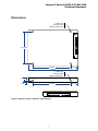
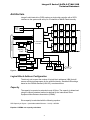
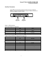
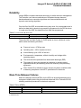
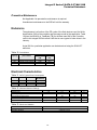
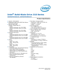
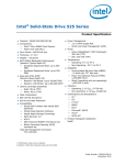
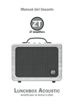
Integral P Series 2 SATA 2.5” MLC SSD
Technical Datasheet
Features:
SATA 2.6 Compliant, 3Gb/s support and 1.5Gb/s support
ATA modes supported
- PIO modes 3 and 4
- Multiword DMA modes 0, 1, 2
- Ultra DMA modes 0, 1, 2, 3, 4, 5, 6
Industry-standard, 512-byte sector size support
Hot-plug capable
Ultra-efficient Block Management & Wear Leveling
Intelligent “Recycling” for advanced free space management
RoHS-compliant package
S.M.A.R.T. (Self-monitoring, analysis, and reporting technology) command set
1
Performance (lifetime)
- Sequential READ: up to 285 MB/s @128K
- Sequential WRITE: up to 280 MB/s @128K
- Random READ: up to 30K IOPs @4K
- Random WRITE: up to 30K IOPs @4K
Endurance: Total bytes written (TBW)
- Up to 5PB
Reliability
2
- MTBF(PoH): 2 million device hours
- Up to 24 9-bit Symbols Correction per 512 9-bit Symbol
- Static and dynamic wear leveling
- Non-recoverable Read Errors: (Less than 1 sector per bits read) 10^16
- Low power consumption: <2.5W (AVE)
Mechanical/electrical
- Standard SATA connector
- 5V power (±10%)
- 2.5-inch drive: 100.mm x 69.75mm x 9.5mm
- Weight: 81g
Operating temperature: 0°C to 70°C
Humidity (operating): 5% to 95% RH
Shock and vibe
- 1500G/0.5ms
- 2–500Hz at 3.1G
Capacity: 60GB, 120GB, 240GB
Notes:
1. Typical I/O performance numbers as measured using Iometer with a queue depth of 32 and write cache enabled.
2. The product shall achieve a mean time between failure (MTBF) of 2.0 million hours, which are based on population
statistics that are not relevant to individual units.
3. 1GB = 1 billion bytes (10004)
2
Integral P Series 2 SATA 2.5” MLC SSD
Technical Datasheet
Dimensions
4 – M3x0.5-6H
Mounting Holes
MIN Full Thread 3 mm
61.72 mm.
76.6 mm.
100 mm.
14 mm.
4 – M3x0.5-6H
Mounting Holes
MIN Full Thread 3 mm
9.5 mm.
3 mm.
76.6 mm.
Figure 1 Integral P Series 2 SATA 2.5" SSD Housing
3
14 mm.
Integral P Series 2 SATA 2.5” MLC SSD
Technical Datasheet
Architecture
Integral’s solid state drive (SSD) employs a single-chip controller with a SATA
interface on the system side and up to 16-channels of NAND Flash internally.
Xtal
SATA Connector
RS-232
De-Bug
Port
Buffer
Flash
0
Flash
1
Flash
2
Flash
3
Flash
8
Flash
9
Flash
10
Flash
11
Flash
4
Flash
5
Flash
6
Flash
7
Flash
12
Flash
13
Flash
14
Flash
15
SF-1200 SATA
Controller
“Activity”
“Fault”
Input Voltage
Supervisor
Core Power
regulator
Low Power
Regulator
Serial
EPROM
Temp
Sensor
DIAG
Figure 2 – SATA Connections
Logical Block Address Configuration
The drive is set to report the number of logical block addresses (LBA) that will
ensure sufficient storage space for the specified density. Standard LBA settings,
based on the IDEMA standard (LBA1-02), are shown below.
Capacity
The capacity is reported as a decimal count of Bytes. The capacity is determined
using the industry standard method as defined by the International Drive
Equipment Manufacturers Association (IDEMA).
Drive capacity is calculated with the following equation:
SSD Capacity in Gbytes = (UserAddressableLBAcount - 21168) / 1953504
Equation 1 IDEMA user capacity calculation
4
Integral P Series 2 SATA 2.5” MLC SSD
Technical Datasheet
Table 1 Integral P Series 2 SSD drive Configurations
User
Capacity
4
(1000 )
60
120
240
Raw
Capacity
4
(1024 )
64
128
256
Wear Level
Provisioning
LBA Count
7%
7%
7%
117,231,408
234,441,648
468,862,128
Performance
Table 2 Integral P Series 2 SSD Drive Configurations
User
Capacity
4
(1000 )
60
120
240
Sequential
Read
Write
(MB/s)
(MB/s)
285
285
285
275
275
275
Random
Read
Write
(IOPS)
(IOPS)
>30K
>30K
>30K
>30K
>30K
>30K
Access
<100 μsec
<100 μsec
<100 μsec
Table 3 Nominal Dimensions and Weights
Signal Name
Height
Width
Length
Unit weight
Type
9.5
69.85
100
81
Description
mm
mm
mm
g
5
Integral P Series 2 SATA 2.5” MLC SSD
Technical Datasheet
Interface Connectors
Integral SSD uses the industry standard 2.5” SATA connector as defined by
SATA-IO. The pin-out of the signal segment is shown in Table 4 and the pin-out
of the power segment is shown in Table 5.
Power
Segment
Signal
Segment
Figure 3 – SATA Connections
Table 4 Signal Segment pin assignments
Signal Name
S1
S2
S3
S4
S5
Type
GND
A+
AGND
B-
Description
Ground
A+ (transmit)
A- (transmit)
Ground
B- (receive)
S6
S7
B+
GND
B+ (receive)
Ground
Table 5 2.5-Inch SATA Power Segment Pin Assignments
Signal Name
P1
P2
P3
P4
P5
Type
V33
V33
V33
GND
GND
Description
No connect
No connect
No connect
Ground
Ground
P6
P7
P8
P9
P10
P11
P12
GND
V5
V5
V5
GND
DAS
GND
Ground
5V power
5V power
5V power
Ground
Device activity signal
Ground
P13
V12
P14
V12
P15
V12
Note: 1. The DAS signal may be optionally connected to GND if an LED is not being used.
6
No connect
No connect
No connect
Integral P Series 2 SATA 2.5” MLC SSD
Technical Datasheet
Commands
Table 6 Supported ATA Command Set
Command Name
CHECK POWER MODE
CHECK POWER MODE
DEVICE CONFIGURATION
FLUSH CACHE
FLUSH CACHE EXT
IDLE
IDLE
IDLE IMMEDIATE
IDLE IMMEDIATE
NOP
READ BUFFER
READ BUFFER DMA
READ DMA
READ DMA EXT
READ DMA (without retries)
READ FPDMA QUEUED
READ LOG DMA EXT
READ LOG EXT
READ MULTIPLE
READ MULTIPLE EXT
READ NATIVE MAX ADDRESS
READ NATIVE MAX ADDRESS EXT
READ SECTORS
READ SECTORS EXT
READ SECTORS (without retry)
READ VERIFY SECTORS
READ VERIFY SECTORS EXT
READ VERIFY SECTORS (without retry)
RECALIBRATE
REQUEST SENSE DATA EXT
SECURITY DISABLE PASSWORD
SECURITY ERASE PREPARE
SECURITY ERASE UNIT
SECURITY FREEZE LOCK
SECURITY SET PASSWORD
SECURITY UNLOCK
SEEK
SET FEATURES
SET MAX ADDRESS
SET MULTIPLE MODE
SET NATIVE MAX ADDRESS EXT
SLEEP
SLEEP
SMART
STANDBY
STANDBY
STANDBY IMMEDIATE
STANDBY IMMEDIATE
WRITE BUFFER
WRITE BUFFER DMA
WRITE DMA
WRITE DMA EXT
Command
Code (hex)
Description
0x98
0xE5
0xB1
0xE7
0xEA
0xE3
0x97
0x95
0xE1
0x00
0xe4
0xe9
0xc8
0x25
0xc9
0x60
0x47
0x2F
0xc4
0x29
0xF8
0x27
0x20
0x24
0x21
0x40
0x42
0x41
0x10
0x0B
0xF6
0xF3
0xF4
0xF5
0xF1
0xF2
0x70
0xEF
0xF9
0xC6
0x37
0x99
0xE6
0xB0
0xE2
0x96
0x94
0xE0
0xE8
0xEB
0xCA
0x35
7
Integral P Series 2 SATA 2.5” MLC SSD
Technical Datasheet
WRITE DMA FUA EXT
WRITE DMA (without retries)
WRITE FPDMA QUEUED
WRITE LOG DMA EXT
WRITE LOG EXT
WRITE MULTIPLE
WRITE MULTIPLE EXT
WRITE MULTIPLE FUA EXT
WRITE SECTORS
WRITE SECTORS EXT
WRITE SECTORS (without retry)
0x3D
0xCB
0x61
0x57
0x3F
0xC5
0x39
0xCE
0x30
0x34
0x31
Smart Attributes
Table 7 S.M.A.R.T Attributes
Reliability Tracking
1
5
13
171/181
172/182
184
187
195
196
198
199
201
204
Usage Statistics
9
12
100
241
242
Life Remaining
170
231
232
Power Loss
174
235
Wear Leveling
177
Temperature
194
Warranty Life Throttling
230
Other
233
234
Raw Read Error Rate
Retired Block Count
Soft Read Error Rate
Program Fail Count
Erase Fail Count
IOEDC Errors
Reported Uncorrectable Errors
ECC On-the-fly Count
Reallocation Event Count
Uncorrectable Sector Count
SATA R-Errors Error Count
Uncorrectable Soft Read Error Rate
Soft ECC Correction Rate (RAISE)
Power On Hours
Device Power Cycle Count
Gigabytes Erased
Lifetime Writes from Host
Lifetime Reads from Host
Reserved Block Count
SSD Life Left
Available Reserved Space
Mobile – P Series 2
X
X
X
X
X
X
X
X
X
X
X
X
X
X
Unexpected Power Loss
Supercap Monitoring
X
Wear Range Delta
X
Temperature
X
Life Curve Status
Internal Reserved
Internal Reserved
X
X
8
Integral P Series 2 SATA 2.5” MLC SSD
Technical Datasheet
Reliability
Integral SSDs incorporate advanced technology for defect and error management.
The Controller uses various combinations of redundant storage elements,
hardware-based error correction algorithms and firmware-based static and
dynamic wear-leveling algorithms.
Over the life of the SSD, uncorrectable errors may occur. An uncorrectable error is
defined as data that is reported as successfully programmed to the SSD but when
it is read out of the SSD, the data differs from what was programmed.
Table 8 Uncorrectable Bit Error Rate
Uncorrectable Bit Error Rate
<1 sector per 1016 bits read
Operation
Read
The product life is at least 5 years or 43,800 power-on hours, whichever comes
earlier under the following conditions:
Power-on hours = 8,760 per year
Operating time = 100% of power-on hours
Active/Idle duty cycle = 90% of the time
Environmental = temperature, altitude, humidity and voltage within
operating ranges
The drive should be protected from electrostatic discharge (ESD)
The product life does not represent any warranty or warranty period.
Applicable warranty and warranty period are covered by the purchasing
agreement.
Note: Product life is defined as time in service at systems conditions while
maintaining compliance to the MTTF specification for the device.
Mean Time Between Failures
Mean time between failures (MTBFs) for the SSD can be predicted based on the
component reliability data using the methods referenced in the Telcordia SR-332
reliability prediction procedures for electronic equipment.
Table 9 Drive MTBFs
Density
MTBF (Operating Hours)1
60
1.5 million
120
1.5 million
1.5 million
240
Note: 1. A mean time between failure (MTBF) of 2.0 million hours is based on population statistics that are not relevant
to individual units.
9
Integral P Series 2 SATA 2.5” MLC SSD
Technical Datasheet
Preventive Maintenance
Not Applicable. No preventative maintenance is required.
Unauthorized maintenance to the SSD will void the warranty.
Endurance
The endurance is a function of the PE cycles of the flash devices used, the Write
Amplification (WA) of the controller and the usage model of the application. Table
10 gives the Write life in TeraBytes (TB) for the best case WA for the Controller
used in this Integral SSD drive and a WA that is more typical of other drives in the
industry.
Actual WA for a particular application can be determined using the S.M.A.R.T.
attributes.
Table 10 Drive lifetime
User
Capacity
Standard MLC based
part numbers
60
120
240
INSSD60GS25MXP2
INSSD120GS25MXP2
INSSD240GS25MXP2
Write Life w/MLC
WA=.5
WA=6
(TB)
(TB)
640
53.3
1280
106.7
2560
213
Electrical Characteristics
Table 11 SATA Typical Power Consumption
Density
Idle
Idle w/DIPM
60
120
240
64
128
256
7%
7%
7%
Sequential
Write/Read
117,231,408
234,441,648
468,862,128
Table 12 Absolute Maximum Ratings
Condition
Voltage Input
Operating Temperature
Symbol
Vs
TA
Non-operating Temperature
Relative Humidity
Min
3.3
0
Max
5.5
70
Unit
V
C
-40
5
85
95
C
%
Table 13 Shock and Vibration
Condition
Operating shock
Operating Vibration
Specification
1500 G / 0.5ms
2-500 Hz at 3.1G
10
Integral P Series 2 SATA 2.5” MLC SSD
Technical Datasheet
Compliance
Integral SSDs comply with the following:
RoHS “green”
CE (Europe): EN55022, 2006 Class B and EN55024, 1998 + A1: 2001 +
A2:2003
FCC: CFR Title 47, Part 15, ICES-003, all Class B
11