1
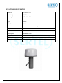
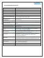
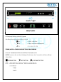
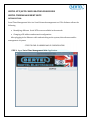
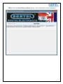
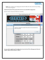
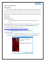
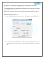
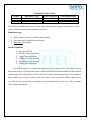
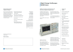
SERTEL ELECTRONICS USER MANUAL GPS RECEIVER T-GPS-300 Contents ABOUT ABOUT 1 DETAILS 1 ABSTRACT 1 INTRODUCTION 2 This document is the Operation & Maintenance, Installation manual for Sertel GPS System. DETAILS 1) Installation Details 2) Settings details GPS ANTENNA SPECIFICATION 3 Benefit 1 GPS RECEIVER SPECIFICATION 4 TIME, DATE & TIME ZONE SETTING PROCEDURE 5 SERTEL NTP/SNTP CONFIGURATION PROCEDURE 7 SERTEL TIME MANAGEMENT SUITE 7 IRIG TIME CODE FORMAT 14 USER'S MANUAL - SAFETY GUIDE 16 ANNEXURE-I 17 Sertel Products are highly user-friendly device. The operations are easy-to-understand and completely simple for the operator to handle. The system requires absolutely less maintenance and has very high MTBFs. ABSTRACT Characteristics and technical details of system & each output is Explained below. INTRODUCTION We are technology oriented company who focus on R&D and High tech Industrial Applications. We are one of the world’s leading manufacturers of highly precise time stamping technologies, solutions for industrial instrumentations. We tailor our solutions for industry verticals such as power sectors, chemical industries, Oil & Gas, civilian networks etc. We support customers with solutions in different parts of the world to monitor, generate, distribute and apply time. Sertel strictly caters products to customer’s industry requirements. Sertel’s Range of Solutions includes: 1. Time Synchronization - All Industry Protocols (IRIG, NTP, IEC61850 etc.) 2. The Time and Frequency Display 3. Alarm Annunciator (Modern and Advanced Features) 4. Signal Isolators - Supports all the Interfaces 5. Innovative SMPS solutions for Niche applications (SMPS ICs Available) 6. Video Time Inserter for Industrial Security Applications 7. RTDs, Thermocouples, Temperature and Pressure Meters 8. Remote Data Monitoring and Transmission 9. Variable Frequency Drive - Crane, Lifting, Granite cutting automation 10. Automatic Vehicle Locator Sertel is an ISO 9001:2000 certified company and is committed to the highest standards of quality. Sertel is committed towards delivering the world-class standards in engineering with its key resources of skilled manpower and equipment. GPS ANTENNA SPECIFICATION Model No T-GPA-014-S15 Geodetic System WGS-84 Tracking Code ‘L’ Band CA Code No. of Channel 8 Channel/ Parallel Type Helical Axial Ratio <4 dB Cable Coaxial cable 50 meter along with matching connectors. Output Connector TNC/BNC Connector Total Gain Over 42 dB Noise Figure Less than 1.3 dB Supply Voltage 5V DC Internal Supply Operating Temperature 0 TO + 55°C Mounting Wall Mounting GPS RECEIVER SPECIFICATION Model Type Display Time Reference Input Input Connector Interface Time Stability of internal time base Propagation Delay Compensation Offset Adjustment Internal Time Base Resynchronization Delay Resynchronization Accuracy Output Rate Output O/P Connector Front Panel T-GPS-300 Micro Controller Type Backlit LC Display 24 Hours Format OCXO with stability of 1 PPM 1575.42 ± 1 MHz from Antenna TNC/BNC Connector TTL (Normal high) Internal stability of better than 1 PPM Better than 1 µs Offset included it will be corrected automatically. System revert to internal time base upon loss of signal from UTC source Less than 2-3 min Better than 1 µs Every Second NTP/SNTP O/P – 02 No’s., IRIG B (AM) O/P- 01 No. & Alarm Contact -02 No’s. (GPS Lost, Power Fail). RJ45 Connector for NTP/SNTP O/P,BNC Connector for IRIG B (AM) O/P &Phoenix Connector for Alarm Contact. LED Indicators, LC Display (2x16) shows Julian days, HH-MM-SS, DD-MM-YYYY, Latitude, Longitude, Time Zone (+5.30), No of Satellites and Keypad. Back Panel 90 to 260V AC/DC input connector with Fuse,ON/OFF Switch, Input & Output Connector, Alarm Contact (GPS Lost, Power Fail). Supply Voltage 90 to 260V AC/DC Operating Temperature : 0 TO 55 °C RH : 0-95% NON CONDENSING To suit standard 19” Rack System 1U (H) X 485 (W) X 325 (D)mm ±5mm Environments Mounting Dimension LCD is placed in front of the GPS System Also three keys are present in front of clock. Key --- Enter to the data Key --- move curser to next character Key ---Increment the data TIME, DATE & TIME ZONE SETTING PROCEDURE FOLLOW THE BELOW STEPS FOR SETTING TIME AND DATE NOTE: Power on the unit then it displays Sertel name, after 3 seconds it will show all time related data. ENTER BUTTON NEXT BUTTON INCREMENT BUTTON STEP 1: GPS UNIT WILL DISPLAY THE FOLLOWING DATA a. LC DISPLAY * TIME * DATE b. By long pressing Next button * TIME ZONE * STATUS * SATELLITES c. By long pressing Increment button * LATTITUDE * LONGITUDE STEP 2: TIME SETTING Time will be displayed in 24 hours format. Press Enter button, Next button will display Now press Increment button to change time. After that press Enter button then only it starts running on set time. The same procedure will be followed to change Date and Time zone. NOTE: Time zone limits from -12:30 TO +12:30 Sertel’s GPS Time Sync Server Configuration is as follows Acquisition/Tracking Specifications Initial Acquisition Time 20 seconds Warm Start Resynchronization Delay 15Minutes Cold Start Less than 2-3 Minutes Horizontal Accuracy (2drms) Vertical Accuracy (2drms) Power Supply Supply Voltage / Current External Back-up power Ambient Conditions 5.6m 7.3m Voltage: 3.0 to 3.6 Vdc Current: Max 72 mA at 3.6 Vdc Voltage: 2.1 to 3.6 Vdc Current: 200 uA when Vcc = 3.6 Vdc 10uA when Vcc = 0.0 Vdc Operating temperature: 0°C - +55°C Storage temperature: -15°C - +90°C SERTEL NTP/SNTP CONFIGURATION PROCEDURE SERTEL TIME MANAGEMENT SUITE INTRODUCTION: Sertel Time Management Suite is a Sertel Network management tool. This Software allows the following Identifying different Sertel NTP servers available in the network Changing of IP address and network configuration. After plugging in the Ethernet cable and switching on the system, this software enables management of system. STEPS TO FIND IP ADDRESS AND IP CONFIGURATION STEP1: Open ‘Sertel Time Management Suite ‘Application. STEP2: Click the ‘Sertel IP Server Finder’ Button. A List of Sertel IPs would be displayed. STEP3: Select the required IP for viewing the IP Configuration details. The Sertel Time Management Suite also allows user to change the IP address. STEP4: Click “Submit” after changing the desired IP Address & reboot the Server by clicking “OK” in the message Box. Automatically Sertel GPS system will restart for successful NTP configuration. We don’t need to reboot the GPS Receiver manually. . On successful completion of IP configuration close the Sertel Time Management Suite and reopen it again and check the IP address. INSTALLATION PROCEDURE INTRODUCTION This document describes the configuration and running of the NTP time synchronization client S/W developed for Windows OS platform. This software fetches the time from any Sertel NTP server and synchronizes the local system time with it. This document describes the necessary steps to install and run the Client s/w to synchronize the server time with the local client systems. INSTALLATION: Installation Requirements: Windows OS (Windows XP-SP3, Windows Vista, Windows 7 & Windows Server 2008) [Note: If using any other Windows OS (other than the ones described above), such as Windows XP-SP2, Windows Server 2003, then please install the .net framework v2.0 which is a free download from the Microsoft site in the below link (http://www.microsoft.com/download/en/details.aspx?id=19)] Needs Admin Privileges to both install and run the software. Installation Procedure: 1. Double-click the “SertelNTPClient Installer” file to start the setup wizard. Follow the instructions in the Setup Wizard to install the Client software on the target computer. On completion of the installation, the application can be accessed from the START MENU. [Start Menu -> All Programs -> Sertel NTPClient 1.2] [To uninstall the software, go to Add/Remove Programs in the Control Panel, and then uninstall the “SertelNTPClient 1.2” software.] [NOTE: Admin Privileges is required to both install and run the software on the target system.] RUNNING THE Sertel NTPClient 1.2: 1. Open the NTPClient from the start menu (Start -> All Programs -> Sertel NTPClient 1.2). 2. In order to change the IP Address of the NTP server, click “Configure” button in the application and enter the new IP address of the Sertel NTP Server (IP of Sertel’s hardware unit). 3. Click the “Start” button to start synchronizing the local system time with that of the NTP server. Note: It is required to run the application with administrator privileges or else the application would throw an “Access Denied” error in the “Sync Status”. Given time will be updated at every zeroth second. Applications It’s main application for SCADA where huge no of GPS are required. In power generation industry to maintain the accurate time to operational failure. Typical application of everyday activities such as computer network timing, utility billing, financial transaction of banking, mobile operation. GPS System has been developed to address key power and process industry time synchronization requirements. IRIG TIME CODE FORMAT IRIG-B standard time format by telecommunication working group. Inter range instrumentation group range commanders council describes IRIG-B it is available by writing secretly range commanders council. White sand missile range New Mexico 880022. The standard time formats of IRIG-B Code were designed for us in missile, satellite and space research programmers. Use of these code facilities efficient interchange of test data. Those formats are suitable for recording on magnetic tape oscillo graphics film and for real time transmission in both automatic manual data reduction. IRIG-B from the SERTEL GPS / MASTER CLOCK system is suitable for remote display driving magnetic tape recording and may other use. IRIG-B codes in the strip sense encode Universal Co-ordinate Time (UTC) in 24 Hours format only, not local time. Nonetheless this instrument can encode UTC and IST time in 24 hours format. The frame length of IRIG-B is 1 second long and contains 100 elements (pulse) each of which starts every 10 millisecond (un modulated) and 1 millisecond (modulated). SERTEL GPS/MASTER CLOCK provides output of IRIG-B in amplitude modulated signal (1 KHz) output at rear panel of BNC Connectors. This will help us long distance communication. The term IRIG signals is frequently used to refer to a whole group of serial time codes, which use a continuous stream of binary data to transmit information on date and time. The individual time code formats can be distinguished by the signal characteristics, e.g. modulated versus unmodulated, which require different ways of signal transmission, by the data rate, and by the kind of information included in the transmitted data. Inter-range instrumentation group time codes, commonly known as IRIG time codes. As per IRIG Standard 200-04, Code Bit rate Bit time IRIG time code Bits per frame Frame time Frame rate B 100 Hz 10 ms 100 1000 ms 1 Hz E 10 Hz 100 ms 100 10 s 0.1 Hz Permissible Code Formats Modulation Type Carrier Frequency Format B E 0,1,2 0,1 0,2,3,4,5 0,1,2 Coded Expressions 0,1,2,3,4,5,6,7 1,2,5,6 The bits are modulated on a carrier. A three-digit suffix specifies the type and frequency of the carrier, and which optional information is included: Modulation type 0. (DCLS) Direct Current Level Shift (width coded) 1. Sine wave carrier (amplitude modulated) 2. Manchester modulated Carrier frequency 0. 1. 2. 3. 4. 5. No carrier (DCLS) 100 Hz (10 ms resolution) 1 kHz (1 ms resolution) 10 kHz (100 µs resolution) 100 kHz (10 µs resolution) 1 MHz (1 µs resolution) The IRIG-E signal is an amplitude modulated 100 Hz audio carrier. The output level is adjustable from 2 to 3 volts peak to peak, and the input will accept levels between 150mV and 3V peak to peak. The code contains 26 bits of BCD time-of-year information in days, hours, minutes, and seconds, with 10 ms resolution. The time code recycles yearly.The IRIG-E signal can be recorded and then played back on magnetic tape, transmitted over the air, or fed to another 9300 using a twisted pair. USER'S MANUAL - SAFETY GUIDE Please read the following points before servicing or installing. • Pre-installation checks - It is recommended that the unit be bench tested prior to installation on the site. • Safety during installation or servicing - Particular care should be taken to isolate the pan/tilt head in order to prevent operation while engineering work is being carried out. In addition any ladder or other means of working on the receiver MUST NOT rest on the pan/tilt head as it is possible for the head to move when not expected. • Safety check - Upon completion of any service or repairs to the unit, safety checks should be performed to ensure that the unit is in proper operating condition. • Coax grounding - If an outside cable system is connected to the unit, be sure the cable system is grounded. • Adhere to Safety Standards - All normal safety precautions as laid down by Indian Standards and the Health and Safety at Work Act should be observed. WARNING - TO PREVENT DANGER OF FIRE OR SHOCK, DO NOT EXPOSE THE INTERNAL COMPONENTS OF THIS EQUIPMENT TO RAIN OR MOISTURE. Damage requiring service - Servicing by qualified personnel should be carried out under the following conditions, (a) (b) If the unit does not operate normally by following the operating instructions. If the unit has been dropped or the enclosure is damaged; Replacement parts - If replacement parts are required, ensure that only replacement parts recommended by the SERTEL are used. AFTER SALES SERVICE Please contact [email protected]/[email protected] M: 0 93850 - 90333. ANNEXURE-I