1
04 557637 ch01.qxd
3/4/04
2:31 PM
Page 23
1
C H A P T E R
Finding Your Way —
Exploring the Max
Interface
✦
✦
✦
✦
In This Chapter
Learning the interface
elements
W
ell, here we are with a new version of Max, and the first question on the minds of existing users is “Did the interface
change?” The answer is a gleeful “not much.” Most serious users
would rather go through root canal surgery than have their user
interface (UI) change, and although Discreet has learned and
respected this valued opinion, you’ll find some minor changes.
As you look around the new interface, you’ll see that everything is
still there, but Max has several clever, new additions. You may find
yourself saying, as you navigate the interface, “where did that come
from?” But, just like encountering a new house in your neighborhood,
over time you’ll become accustomed to the addition and might even
meet some new friends.
Why is the software interface so important? Well, consider this: The
interface is the set of controls that enables you to access the program’s features. Without a good interface, you may never use many
of the best features of the software or spend a frustrating bit of time
locating it. A piece of software can have all the greatest features, but
if the user can’t find or access them, then the software won’t be used
to its full potential. Max is a powerful piece of software with some
amazing features, and luckily, the interface makes these amazing features easy to find and use.
The interface is all about making the features accessible, and in Max
you have many different ways to access the same command. Some of
these access methods are faster than others. This design is intentional because it gives beginning users an intuitive command and
advanced users direct access. For example, to undo a command, you
can choose Edit ➪ Undo (requiring two mouse clicks), but as you gain
more experience, you can simply click the Undo icon on the toolbar
(only one click); an expert with his hands on the keyboard will press
Ctrl+Z without having to reach for the mouse at all. All three of these
methods have the same result, but you can use the one that is easiest
for you.
Has the Max interface succeeded? Yes, to a degree, but like most
interfaces, it always has room for improvement, and we hope that
Previewing the
menu commands
Becoming familiar
with the toolbars
Using the Command
Panel
Examining the Lower
Interface Bar
Interacting with
the interface
Getting help
✦
✦
✦
✦
04 557637 ch01.qxd
24
3/4/04
2:31 PM
Page 24
Part I ✦ Learning the Max Interface
each new version takes us closer to the perfect interface (but I’m still looking for the “read
my thoughts” feature). Discreet has built a loophole into the program to cover anyone who
complains about the interface — customization. If you don’t like the current interface, you
can change it to be exactly what you want.
CrossReference
Customizing the Max interface is covered in Chapter 4, “Customizing the Max Interface and
Setting Preferences.”
This chapter examines the latest incarnation of the Max interface and presents some tips that
make the interface feel comfortable, not cumbersome.
Tip
If you are an existing user, I’ve made liberal use of the New Feature icon throughout this
chapter to highlight what has changed with this edition. If you’re anxious to get to the new
stuff, I’d suggest that you quickly scan this chapter looking for the New Feature icons, which
refer you to the chapters where the new features are covered.
The Interface Elements
If you’re new to the Max interface, the first order of business is to take a stroll around the
block and meet the neighbors. The Max interface has a number of interface elements that
neatly group all the similar commands together. For example, all the commands for controlling the viewports are grouped together in the Viewport Navigation Controls found in the
lower-right corner of the interface.
Note
If all the details of every interface command were covered in this chapter, it would be an
awfully long chapter. So I include a simple cross-reference to the chapter where more information can be found about each command.
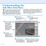
The entire interface can be divided into five easy elements. Each of these interface elements,
in turn, has groupings of sub-elements. The five main interface elements are listed here and
shown in Figure 1-1:
✦ Menus: This is the default source for most commands, but also one of the most timeconsuming interface elements. The menus are found along the top edge of the Max
window.
✦ Toolbars: Max includes several toolbars of icon buttons that provide single-click access
to features. These toolbars can float independently or can be docked to an interface
edge.
✦ Viewports: Four separate views into the scene show the Top, Front, Left, and
Perspective viewpoints.
✦ Command Panel: The major control panel located to the right of the four viewports, it
has six tabbed icons at its top that you can click to open the various panels. Each panel
includes rollouts containing parameters and settings. These rollouts change depending
on the object and tab that is selected.
✦ Lower Interface Bar: Along the bottom edge of the interface window is a collection of
miscellaneous controls.
04 557637 ch01.qxd
3/4/04
2:31 PM
Page 25
Chapter 1 ✦ Finding Your Way — Exploring the Max Interface
Main toolbar
Docked toolbar
Menus
Lower Interface Bar
Command Panel
Viewports
Figure 1-1: Max includes five main interface elements.
In addition to these default elements are several additional interface elements that you will
find useful. These controls aren’t initially visible when Max is first loaded, but they can be
accessed by working with the interface. These additional interface elements include the
following:
✦ Floating toolbars: Several toolbars are available as floating toolbars by default, but you
can create more if you like. You access them by choosing Customize ➪ Show UI ➪ Show
Floating Toolbars or by selecting them from the toolbar’s right-click pop-up menu.
✦ Quadmenus: Right-clicking on the active viewport makes a pop-up menu with up to
four panes appear. This is called a quadmenu. Quadmenus offer context-sensitive commands based on the object or location being clicked.
✦ Dialog boxes and editors: Some commands open a separate window of controls. These
dialog boxes may contain their own menus, toolbars, and interface elements. A good
example of this element is the Material Editor, which has enough controls to keep you
busy for a while.
25
04 557637 ch01.qxd
26
3/4/04
2:31 PM
Page 26
Part I ✦ Learning the Max Interface
Using the Menus
The pull-down menus at the top of the Max interface include most of the features available in
Max and are a great place for beginners to start. Several of the menu commands have corresponding toolbar buttons and keyboard shortcuts. To execute a menu command, you can
choose it from the menu with the mouse cursor, click its corresponding toolbar button if it
has one, or press its keyboard shortcut. You can also select the command using the keyboard
arrows and press the Enter key to execute it, but I’m sure you already knew that.
The main menu includes the following options: File, Edit, Tools, Group, Views, Create,
Modifiers, Character, reactor, Animation, Graph Editors, Rendering, Customize, MAXScript,
and Help. Unlike some other programs, these menu options do not disappear if not needed.
The list is set, and they are always there when you need them.
The reactor menu is new in 3ds max 6.
New
Feature
If a keyboard command is available for a menu command, it is shown to the right of the menu
item. If an ellipsis (three dots) appears after a menu item, that menu command causes a separate dialog box to be opened. A small black arrow to the right of a menu item indicates that a
submenu for this item exists. Clicking the menu item or holding the mouse over the top of a
menu item makes the submenu appear. Toggle menu options (such as Views ➪ Show
Ghosting) change state every time they are selected. If a toggle menu option is enabled, a
small check mark appears to its left; if disabled, no check mark appears.
CrossReference
A complete list of keyboard shortcuts can be found in Appendix C, “Max Keyboard Shortcuts.”
You can also navigate the menus using the keyboard by pressing the Alt key by itself. Doing
so selects the File menu, and then you can use the arrow keys to move up and down and
between menus. With a menu selected, you can press the keyboard letter that is underlined
to select and execute a menu command. For example, pressing Alt, then F (for File) and N (for
New) executes the File ➪ New command; or you can press Alt, use the down arrow to select
the New command, and press the Enter key.
Tip
By learning the underlined letters in the menu, you can use the keyboard to quickly access
menu commands, even if the menu command doesn’t have an assigned keyboard shortcut.
And because you don’t need to stretch for the Y key while holding down the Ctrl key, underlined menu letters can actually be faster. For example, pressing Alt, G, and U successively, you
can access the Group ➪ Ungroup menu command. The keyboard buffer remembers the
order of the letters you type regardless of how fast they are keyed, making it possible to
quickly access menu commands using the keyboard. Over time, you can learn patterns to
help you remember how to access certain menu commands, such as Alt, C, H, E for creating
an ellipse.
Not all menu commands are available at all times. If a menu command is unavailable, then it
is grayed out and you cannot select it. For example, the Clone command is available only
when an object is selected, so if no objects are selected, the Clone command is grayed out
and unavailable. After you select an object, this command becomes available.
04 557637 ch01.qxd
3/4/04
2:31 PM
Page 27
Chapter 1 ✦ Finding Your Way — Exploring the Max Interface
The File menu
The File menu includes commands for working with Max files. These commands enable you
to create a new scene, open and save scene files and objects, and work with externally referenced (XRefs) objects and scenes. You can also reset the scene, merge scenes and animation
sequences, and replace objects in the current scene. The File menu also includes commands
to import and export objects.
At the bottom of the File menu, the Archive command copies all files used in a scene to an
easily portable archive file format. The Summary Info and File Properties commands open
dialog boxes where you can get information about the current scene file. The View Image File
command opens a dialog box where you can view an image before loading it, and the Exit
command ends the madness if you’ve had too much.
CrossReference
Because most of the commands found in the File menu affect files, you can find information
about these commands in Chapter 3, “Working with Files and XRefs.”
The Edit menu
The Edit menu wins an award for having the most listed keyboard shortcuts per menu item
of all the menus. It includes commands for recovering from mistakes (Undo and Redo),
preparing for catastrophe (Hold and Fetch), and the ubiquitous Delete. The Hold command
(Alt+Ctrl+H) saves the current scene in a buffer. This scene can be recalled at any time using
the Fetch (Alt+Ctrl+F) command. These simple commands can really save your bacon if you
remember to use them. The Edit menu also includes a Clone command (Ctrl+V) for making
copies of an object, which is covered in (no surprise) Chapter 7, “Cloning Objects and
Creating Object Arrays.”
The Edit menu also includes several commands for selecting objects — Select All (Ctrl+A),
Select None (Ctrl+D), Select Invert, and Select By Color and/or Name (H). You can also specify
the type of selection region and whether objects are selected by dragging the cursor across
the object (Crossing) or by enclosing the entire object in the dragged region (Window). The
Edit Named Selection Sets command opens a dialog box where you can name a selected set of
objects for easy recalling. Finally, the Object Properties command opens a dialog box where
you can find all the properties for the selected object.
CrossReference
Most of the Edit menu commands are covered in Chapter 6, “Selecting Objects and Setting
Object Properties.”
The Tools menu
The Tools menu can be considered dialog box heaven because almost every menu command
opens a dialog box. The Transform Type-In (F12) command opens a dialog box that lets you
enter precise values for moving, rotating, and scaling objects (see Chapter 10, “Transforming
Objects — Translate, Rotate, and Scale”). The Display Floater opens a dialog box where you
can hide, freeze, and set the object display options. The Selection Floater (H) opens a dialog
box that lets you select objects by several different criteria. The Layer Manager lets you specify and work with layers. The Display and Selection Floater dialog boxes, along with the Layer
Manager, are covered in Chapter 6 on selecting objects.
27
04 557637 ch01.qxd
28
3/4/04
2:31 PM
Page 28
Part I ✦ Learning the Max Interface
Note
A floater is a unique type of dialog box. It can stay open and active while you work in
the viewports. Normal dialog boxes do not allow this and must be closed before you can
continue.
The Light Lister command opens a dialog box with details on all the lights in the scene. You
can learn to use this helpful dialog box in Chapter 27, “Basic Lighting Techniques.”
The Mirror command uses the Mirror dialog box to create a symmetrical copy of an object
across a designated axis. The Array command opens an Array dialog box where you can create multiple instances of an object with each instance offset from the others. The Snapshot
command clones objects over time using the Snapshot dialog box. The Spacing Tool command (Shift+I) opens the Spacing Tool dialog box, which creates and spaces objects along a
path. All of these commands are different ways to clone objects and create object arrays,
which are covered in Chapter 7.
The Tools menu also includes several ways to align objects. The Align command (Alt+A)
opens an Align dialog box where you can line up objects by axis, edges, or centers. The
Normal Align command (Alt+N) enables you to align the face normals of two objects. The
Align Camera command moves the selected camera to be directly in front of the point you
select, and the Align to View command aligns the object to one of the standard views. Place
Highlight (Ctrl+H) moves the selected light in order to reproduce a highlight in the location
you specify. The alignment commands are covered in Chapter 10 on transforms; the Place
Highlight command is covered with basic lighting in Chapter 27.
The Isolate Selection (Alt+Q) command hides all objects except for the selected object. It also
opens a simple dialog box with an Exit Isolation button in it. Clicking this button or selecting
the Isolate command again exits isolation mode and displays all the objects again. This command is another way to select an object and is covered in Chapter 6. The Rename Objects
command opens the Rename Objects dialog box where you can rename several objects at
once. This command is covered along with naming objects in Chapter 5, “Creating and Editing
Primitive Objects.”
Several standard utilities (Assign Vertex Colors, Color Clipboard, and Camera Match) that
were previously accessed from the Utilities panel have graduated to become real menu commands. You can find these new additions at the bottom of the Tools menu. In addition to
these new menu commands, several new features have been added to the Tools menu,
including Grab Viewport, Measure Distance, and Channel Info.
New
Feature
The Assign Vertex Colors, Color Clipboard, and Camera Match menu commands open and
select their respective utilities in the Utilities panel. The Grab Viewport command is a nice
new feature that captures a picture of the active viewport. The Measure Distance command
provides an easy way to measure the distance between two points. The Channel Info command
opens the Map Channel Info dialog box where you can add objects to a specific channel, which
game developers will appreciate.
CrossReference
The details on the Tools menu commands are spread across the rest of the book, but the
Assign Vertex Colors and Channel Info features deal with games and are covered in Chapter 50,
“Max and Games.”
04 557637 ch01.qxd
3/4/04
2:31 PM
Page 29
Chapter 1 ✦ Finding Your Way — Exploring the Max Interface
The Group menu
The Group menu commands let you control how objects are grouped together. Grouping
objects together becomes key as you begin to move objects because grouped objects all
move together. Selecting several objects and using the Group command opens a simple dialog
box where you can type a name for the group. The Ungroup command disassembles the
group and is active only if a group is selected. You can nest groups one inside another. You
can also open and close groups, which lets you attach or detach objects from the group or
move individual group objects within the group. The Explode command ungroups all nested
group objects.
CrossReference
For a more complete examination of groups and grouping, check out Chapter 8, “Grouping
and Linking Objects.”
The Assembly submenu includes all the same commands as the Group menu including Open,
Close, Attach, Detach, and Explode, but assemblies are unique in that they can have a light
source as a head object. Assemblies are covered along with groups in Chapter 8.
New
Feature
The Assembly feature is new to 3ds max 6.
The Views menu
The Views menu includes commands for controlling the viewports. The Undo View Change
(Shift+Z) and Redo View Change (Shift+Y) commands give you control over viewport
changes, enabling you to undo and redo any changes made with the Viewport Navigation
Controls. You can also save and restore each viewport’s active view with the Save Active View
and Restore Active View commands.
Note
Keep in mind that Undo View Change (Shift+Z) is distinct from undoing changes made to
the current object accomplished with the Edit ➪ Undo (Ctrl+Z) command.
Grids are helpful in establishing your bearings in 3D space. The Grids command opens a submenu with the following options: Show Home Grid, Activate Home Grid, Activate Grid Object,
and Align Grid to View. Grids are covered in Chapter 10 as part of transforming objects.
The Viewport Background command (Alt+B) opens a dialog box in which you can select an
image or animation to appear as a background behind a viewport. If the background image
changes, you can update the viewport using the Update Background Image command
(Alt+Shift+Ctrl+B). The Reset Background Transform command automatically rescales and
recenters the background image to fit the viewport.
Next on the Views menu are several commands that control what is displayed in the viewport. If a command is enabled, a check mark appears to the left of the command. The Show
Transform Gizmo command displays axes and special handles to move, rotate, and scale the
object in different directions. The Show Ghosting command displays the position of the
selected object in the previous several frames, the next several frames, or both. The Show
Key Times command displays frame numbers along the trajectory path where every animation key is located. The Shade Selected command turns on shading for the selected object in
all viewports, and the Show Dependencies command shows any objects that are linked or
instanced from a parent object.
29
04 557637 ch01.qxd
30
3/4/04
2:31 PM
Page 30
Part I ✦ Learning the Max Interface
The Create Camera from View (replacing the Match Camera to View) command (Ctrl+C) creates a camera and positions it to match the current view. The Add Default Lights to Scene
command converts the default lights to actual light objects in the scene. This feature lets you
start with the default lights and modify them as needed.
Caution
The keyboard shortcut for the Create Camera from View command is Ctrl+C, which is the
same as the commonly used Copy command in most other Windows programs. The concepts of Cut, Copy, and Paste don’t really work in Max, and you might find yourself using this
keyboard shortcut by accident occasionally. If you find that you’ve used this command incorrectly, you can use the Undo View Change (Shift+Z) to undo the change.
The Redraw All Views (keyboard shortcut, `) command refreshes each viewport and makes
everything visible again (as objects get moved around, they often mask one another and lines
disappear). Activate All Maps turns on all maps, and Deactivate All Maps turns off all maps.
Material maps can take up lots of memory and can slow the viewport rendering. Update
During Spinner Drag causes a viewport to interactively show the results of a parameter value
change set with spinner controls. Spinners are controls with up and down arrows to their
right that can be changed by clicking and dragging on the control. The Adaptive Degradation
Toggle (O) is an option that enables the animation to degrade the image resolution (by downgrading the rendering method) in order to maintain a consistent frame rate. This can help
when you’re trying to perfect the timing of an animation sequence and you don’t need the
prettiest-looking images in the viewports.
The Expert Mode command (Ctrl+X) maximizes viewport space by removing the menus, main
toolbar, Command Panel, Viewport Navigation buttons, status bar, and prompt line from the
interface.
CrossReference
Most of the Views menu commands are covered in detail in Chapter 2, “Seeing It All —
Working with the Viewports.”
The Create menu
The Create menu includes an easy way to create objects without your having to access the
Command Panel. Selecting an object from the Create menu automatically opens the Create
panel and selects the correct category, subcategory, and button needed to create the object.
After selecting the menu option, you simply need to click in one of the viewports to create
the object.
Several new categories have been added to the Create menu in 3ds max 6, including AEC
Objects, Compound, Patch Grids, NURBS, Dynamics, Helpers, Space Warps, and Systems. The
previous categories must have been really lonely.
New
Feature
The Create menu includes several categories, and you can find a corresponding button for
each submenu item in the Command Panel. Table 1-1 lists the Create menu and submenus.
CrossReference
Almost all the submenus found in the Create menu have a chapter dedicated to them. For
example, coverage of primitive objects can be found in Chapter 5, “Creating and Editing
Primitive Objects.” The one exception is the Helpers category, which is scattered throughout
many chapters, but you can find several helpers discussed in Chapter 12, “Modeling Basics.”
04 557637 ch01.qxd
3/4/04
2:31 PM
Page 31
Chapter 1 ✦ Finding Your Way — Exploring the Max Interface
Table 1-1: Create Menu Items
Menu
Submenu Items
Standard Primitives
Plane, Box, Cone, Sphere, GeoSphere, Cylinder, Tube, Torus, Pyramid, Teapot
Extended Primitives
Hedra, Torus Knot, Chamfer Box, Chamfer Cylinder, Oil Tank, Capsule, Spindle,
L-Extrusion, C-Extrusion, RingWave, Hose, Prism
AEC Objects
Foliage, Railing, Wall, Terrain, Pivot Door, Sliding Door, BiFold Door, Straight
Stair, L-Type Stair, U-Type Stair, Spiral Stair, Awning Window, Casement
Window, Fixed Window, Pivoted Window, Sliding Window, Projected Window
Compound
Morph, Scatter, Conform, Connect, BlobMesh, ShapeMerge, Boolean, Terrain,
Loft, Mesher
Particles
Particle Flow Source, Spray, Snow, Blizzard, PArray, PCloud, Super Spray
Patch Grids
Quad Patch, Tri Patch
NURBS
CV Surface, Point Surface, CV Curve, Point Curve
Dynamics
Damper, Spring
Shapes
Line, Rectangle, Section, Arc, Circle, Donut, Ellipse, Helix, NGon, Star, Text
Lights
Standard Lights (Target Spotlight, Free Spotlight, Target Directional,
Directional, Omni, Skylight, mr Area Spot, mr Area Omni), Photometric Lights
(Target Point, Free Point, Target Linear, Free Linear, Free Area, Target Area,
Presets), Daylight System
Cameras
Free Camera, Target Camera, Create Camera from View (Ctrl+C)
Helpers
Dummy, Point, Grid, Tape Measure, Protractor, Compass, Camera Point,
Atmospherics (Box Gizmo, Cylinder Gizmo, Sphere Gizmo), Manipulators
(Slider, Plane Angle, Cone Angle), Particle Flow (Speed by Icon, Find Target),
VRML 97 (Anchor, Audio Clip, Background, Billboard, Fog, Inline, LOD,
NavInfo, ProxSensor, Sound, TimeSensor, TouchSensor)
SpaceWarps
Forces (Motor, Push, Drag, Vortex, Path Follow, PBomb, Displace, Gravity,
Wind), Deflectors (PDynaFlect, POmniFlect, SDynaFlect, SOmniFlect,
SDeflector, UDynaFlect, UOmniFlect, UDeflector, Deflector),
Geometric/Deformable [FFD(Box), FFD(Cyl), Wave, Ripple, Displace, Conform,
Bomb], Modifier-Based (Bend, Noise, Skew, Taper, Twist, Stretch)
Systems
Bones IK Chain, Daylight System
The Modifiers menu
The Modifiers menu offers a way to apply modifiers without your having to go to the Modify
panel. Before you can apply a modifier, you must select an object. Only the modifiers that you
can apply to the selected object are enabled.
31
04 557637 ch01.qxd
32
3/4/04
2:31 PM
Page 32
Part I ✦ Learning the Max Interface
The Modifiers menu has two new categories in 3ds max 6 — Conversion and Cameras. You’ll
also find a handful of new modifiers including the Select by Channel, UVW Mapping Add,
UVW Mapping Clear, Shell, and Camera Correction.
New
Feature
Selecting a modifier from the Modifiers menu automatically opens the Modify panel where
you can adjust the Parameters for the applied modifier. The modifiers in the Modifiers menu
are grouped into several categories listed in Table 1-2.
CrossReference
Modifiers can be used to help you in many areas such as modeling and animation, so coverage of them is found throughout the entire book, but a general discussion of modifiers and
how to use them is presented in Chapter 11, “Introducing Modifiers for Basic Object
Deformation.”
Table 1-2: Modifiers Menu Items
Menu
Submenu Items
Selection Modifiers
Mesh Select, Poly Select, Patch Select, Spline Select, Volume Select, FFD
Select, Select by Channel
Patch/Spline Editing
Edit Patch, Edit Spline, Cross Section, Surface, Delete Patch, Delete Spline,
Lathe, Normalize Spline, Fillet/Chamfer, Trim/Extend
Mesh Editing
Cap Holes, Delete Mesh, Edit Mesh, Edit Normals, Extrude, Face Extrude,
MultiRes, Normal Modifier, Optimize, Smooth, STL Check, Symmetry,
Tessellate, Vertex Paint, Vertex Weld
Conversion
Turn to Mesh, Turn to Patch, Turn to Poly
Animation Modifiers
Skin, Morpher, Flex, Melt, Linked XForm, PatchDeform, PatchDeform (WSM),
PathDeform, PathDeform (WSM), SurfDeform, SurfDeform (WSM), SplineIk
Control
UV Coordinates
UVW Map, UVW Mapping Add, UVW Mapping Clear, UVW XForm, MapScaler
(WSM), Unwrap UVW, Camera Map (WSM), Camera Map
Cache Tools
Point Cache, Point Cache (WSM)
Subdivision Surfaces
MeshSmooth, HSDS Modifier
Free Form Deformers
FFD 2x2x2, FFD 3x3x3, FFD 4x4x4, FFD Box, FFD Cylinder
Parametric Deformers
Bend, Taper, Twist, Noise, Stretch, Squeeze, Push, Relax, Ripple, Wave, Skew,
Slice, Shell, Spherify, Affect Region, Lattice, Mirror, Displace, XForm, Preserve
Surface
Material, Material By Element, Disp Approx, Displace Mesh (WSM)
NURBS Editing
Surface Select, Surf Deform, Disp Approx
Radiosity Modifiers
Subdivide (WSM), Subdivide
Cameras
Camera Correction
04 557637 ch01.qxd
3/4/04
2:31 PM
Page 33
Chapter 1 ✦ Finding Your Way — Exploring the Max Interface
The Character menu
The Character menu lets you create and work with characters as separate entities. The
Create and Destroy Character commands add characters to or delete characters from the
scene. Characters can be locked or unlocked to allow free movement. Characters can also
be saved as a separate entity and inserted into another scene.
The Bone Tools command opens a dialog box where you can edit the underlying bone system. Characters also have skin, and the Character menu includes commands for setting and
assuming a skin pose.
CrossReference
To learn about characters in more detail, see Chapter 35, “Rigging Characters.”
The reactor menu
The reactor menu includes everything you need to access the reactor physics simulation
engine. With reactor, you can define objects as rigid bodies like chairs or bowling balls or as
soft bodies like stuffed animals. You can also define specialized objects including cloth and
rope.
Although reactor isn’t new to Max 6, the upgraded version of reactor called reactor 2, which
includes many new features, is new. Max 6 has included reactor as a menu item to provide
easy access to these features.
New
Feature
After physical properties are defined, you can define physical forces to act on these objects
and simulate the resulting animation. Not only does reactor make difficult physical motions
realistic, but it also is fun to play with.
CrossReference
Because reactor is the heart of dynamics in Max, you can find it in the part of this book that
covers dynamics, specifically, Chapter 40, “Animating with reactor.”
The Animation menu
The Animation menu contains many commands that help in producing animation sequences
such as IK Solvers, Constraints, and Controllers. The IK Solvers menu command lets you
select from a submenu of Inverse Kinematics (IK) Solvers. The options include HI Solver, HD
Solver, IK Limb Solver, and SplineIK Solver.
The Constraints menu includes options that limit the motion of an object during an animation
sequence. This feature is helpful for keeping the movement of objects within certain boundaries. Controllers, like Constraints, are parameter-driven options for animating objects. Table
1-3 lists the available Constraints and Controllers.
33
04 557637 ch01.qxd
34
3/4/04
2:31 PM
Page 34
Part I ✦ Learning the Max Interface
Table 1-3: Constraints and Controllers Menu Items
Menu
Submenu Items
Constraints
Attachment Constraint, Surface Constraint, Path Constraint, Position
Constraint, Link Constraint, Look-At Constraint, Orientation Constraint
Transform Controllers
Link Constraint, Position/Rotation/Scale, Script
Position Controllers
Audio, Bézier, Expression, Linear, Motion Capture, Noise, Quaternion (TCB),
reactor, Spring, Script, XYZ, Attachment Constraint, Path Constraint, Position
Constraint, Surface Constraint
Rotation Controllers
Audio, Euler XYZ, Linear, Motion Capture, Noise, Quaternion (TCB), reactor,
Script, Smooth, Look-At Constraint, Orientation Constraint
Scale Controllers
Audio, Bézier, Expression, Linear, Motion Capture, Noise, Quaternion (TCB),
reactor, Script, XYZ
The Add Custom Attribute menu command opens the Add Parameter dialog box. Using this
dialog box, you can add new parameters to an object. These new parameters, once defined,
show up in the Custom Attributes rollout of the Command Panel. You can use the Wire
Parameters menu command and Parameter Wire dialog box to make objects respond to the
changes of another object. For example, you can make a character object move up a tree
when a bear character moves closer.
Previews give you a chance to see your animation (rendered in the active viewport) before
you spend time rendering it. Preview commands include Make Preview, View Preview, and
Rename Preview. Previews are saved to a temporary buffer.
CrossReference
Although the basics of animation, including parameter wiring and previews, are covered in
Chapter 30, “Animation Basics,” Constraints and Controllers are covered in Chapter 31,
“Animating with Constraints and Controllers,” and the IK Solvers are covered in Chapter 37,
“Using Inverse Kinematics.”
The Graph Editors menu
The Graph Editors menu includes commands for opening the Track View (including the Curve
Editor and Dope Sheet), the Schematic View and the Particle View (keyboard shortcut, 6)
windows, along with several menus of commands for creating, opening, and deleting saved
views. The Track View editors provide a detailed way to examine the object and animation
parameters as graphs and bars.
The Schematic View is a high-level, node-based view of the scene. It actually provides the easiest way to link objects and clearly represents the relationships between different objects.
New
Feature
The newcomer in this menu is Particle View. The Schematic View interface has been
endowed with many new features.
04 557637 ch01.qxd
3/4/04
2:31 PM
Page 35
Chapter 1 ✦ Finding Your Way — Exploring the Max Interface
The Particle View interface (keyboard shortcut, 6) lets you control how particles interact
with the scene. Using icons that can be linked into a workflow, you can specify how particles
act with one another and with objects in the scene.
CrossReference
The Track View is covered in Chapter 33, “Working with the Track View,” The Schematic View
interface is covered in Chapter 9, “Working with the Schematic View,” and the Particle View
interface is covered in Chapter 18, “Creating Particles and Particle Flow.”
The Rendering menu
The Rendering menu is the doorway to the final output. The Render command (F10) opens
the Render Scene dialog box where you can set output options such as which frames to render and the final image size. The Environment command (keyboard shortcut, 8) opens the
Environment dialog box where you can specify the environment settings such as a background color or image, global lighting settings, and atmospheric effects such as Combustion,
Fog, and Volume Lights.
The Effects command opens the Rendering Effects dialog box. You use the Rendering Effects
dialog box to add rendered effects to an image without having to use the Video Post dialog
box. The Effects categories include options such as Lens Effects, Blur, and Color Balance. The
Advanced Lighting command opens a control panel where the settings for the Light Tracer,
Radiosity, Exposure Control, and Lighting Analysis tools are located.
New
Feature
The Rendering menu holds several features new to 3ds max 6; foremost is the inclusion of
the mental ray rendering engine. Also new to 3ds max 6 are the Panorama Exporter and the
Print Size Wizard.
The Render to Texture command (keyboard shortcut, 0) allows you to render the current
scene as an image to be used as a texture. The Raytracer Settings command opens a dialog
box for enabling raytracing options, and the Raytrace Global Include/Exclude command
opens a dialog box where you can specify which objects are rendered using raytracing and
which are not. The mental ray Message Window opens a window where you can view error
and status messages produced by the mental ray rendering engine.
The ActiveShade Floater opens the ActiveShade window, where you can get immediate rendered results. The ActiveShade Viewport command displays the immediate rendered results
in the active viewport. The Material Editor (keyboard shortcut, M) and Material/Map Browser
commands open their respective dialog boxes for creating, defining, and applying materials.
The Video Post command opens a dialog box for scheduling and controlling any postprocessing work. The dialog box manages events for compositing images and including
special effects such as glows, lens effects, and blurs. The Show Last Rendering command
immediately recalls the last rendered image produced by the Render command.
The Panorama Exporter command allows you to render a panoramic scene. The Print Size
Wizard is a godsend for anyone who is printing images from Max. It relates the current scene
to the common paper sizes that printers use. The RAM Player can display images and animations in memory and includes two channels for overlaying images and comparing animations
side by side.
35
04 557637 ch01.qxd
36
3/4/04
2:31 PM
Page 36
Part I ✦ Learning the Max Interface
CrossReference
The basics of rendering are covered in Chapter 41, “Rendering Basics.” More advanced rendering topics, including Atmospheric Effects and Raytracing, are covered in the subsequent
chapters found in Part X. The Material Editor is covered in Chapter 19, “Exploring the Material
Editor,” and the Video Post dialog box is covered in Chapter 47, “Using the Video Post
Interface.”
The Customize menu
The Customize menu provides commands for customizing and setting up the Max interface.
The Customize User Interface command opens the Customize User Interface dialog box. This
dialog box includes panels for customizing the keyboard shortcuts, the toolbars, quadmenus,
menus, and colors. The Load Custom UI and Save Custom UI As commands let you load and
save different custom interfaces. If your customization creates more problems than it solves,
you can switch back and forth between your custom UI and the defaults with the Custom UI
and Defaults Switcher command.
The Show UI menu contains a submenu of interface elements that you can toggle on or off.
Elements that you can toggle include the Command Panel, Floating Toolbars, the main toolbar (Alt+6), and the Track Bar.
A random click and drag can really mess up your interface. To prevent this from happening,
you can lock the interface. The Lock UI Layout prevents an interface from being changed.
This feature is helpful if you accidentally keep dragging toolbars out of place. The Configure
Paths command opens the Configure Paths dialog box where you can define all the default
paths. These paths let Max know where it can find things like plug-ins, scenes, materials,
and so on.
The Units Setup command opens the Units Setup dialog box for establishing system units.
The Grid and Snap Settings command opens the Grid and Snap Settings dialog box for controlling grid objects and determining which points to snap to.
The Viewport Configuration command lets you configure the viewport using the Viewport
Configuration dialog box. The Plug-in Manager command opens the Plug-in Manager dialog
box, which contains a detailed list of all the loaded plug-ins. This dialog box includes the
plug-in name, description, status, size, and its full path. The Preferences command opens the
Preference Settings dialog box for controlling many aspects of Max.
CrossReference
You can learn about most of the commands found in the Customize menu in Chapter 4,
“Customizing the Max Interface and Setting Preferences,” except for Viewport Configuration,
which is covered in Chapter 2, “Seeing It All — Working with the Viewports.”
The MAXScript menu
From the MAXScript menu, you can create, open, and run scripts. You can also open the
MAXScript Listener (F11) and enable the Macro Recorder. The MAXScript menu also includes
a command for loading the Visual MAXScript Editor, which simplifies the process of building
scripts.
CrossReference
Chapter 48, “Automating with MAXScript,” covers the basics of MAXScript.
04 557637 ch01.qxd
3/4/04
2:31 PM
Page 37
Chapter 1 ✦ Finding Your Way — Exploring the Max Interface
The Help menu
The Help menu is a valuable resource that provides access to reference materials and tutorials. The New Features Guide, User Reference, and MAXScript Reference are comprehensive
help systems that work like a Web browser. The Tutorial command loads the tutorials, which
offer a chance to gain valuable experience.
The Hotkey Map displays an interactive interface for learning all the keyboard shortcuts.
Additional Help presents help systems for any external plug-ins that are loaded. The 3ds max
on the Web options (Online Support, Updates, Resources, and Partners) automatically opens
a Web browser and loads the Discreet Support Web pages or looks for updates.
The Authorize 3ds max command lets you enter an authorization number to authorize the
software. The About 3ds max command opens the About dialog box. This dialog box displays
the serial number and current display driver.
CrossReference
Most of the Help menu commands are covered at the end of this chapter in the section titled
“Getting Help.”
Using the Toolbars
Now that you’ve learned the menu two-step, it is time for the toolbar one-step. The main toolbar appears by default directly under the menus at the top of the Max window; the reactor
toolbar appears docked to the left edge of the interface. Using toolbars is one of the most
convenient ways to execute commands because most commands require only a single click.
You can make any docked toolbar a floating toolbar by clicking and dragging the two vertical
lines on the left (or top) end of the toolbar away from the interface edge. After you separate it
from the window, you can resize the floating toolbar by dragging on its edges or corners. You
can then drag and dock it to any of the window edges or double-click on the toolbar title to
automatically dock the toolbar to its latest location. Figure 1-2 shows the main toolbar as a
floating panel.
If you right-click on any toolbar away from the buttons, you can access a pop-up menu
that includes options to Dock, Float, Customize, show, or hide any of the toolbars or the
Command Panel. You can also show or hide all floating toolbars or the main toolbar with
the Customize ➪ Show UI menu command. The main toolbar can be hidden with the Alt+6
keyboard shortcut.
Figure 1-2: The main toolbar includes buttons and
drop-down lists for controlling many of the most popular
Max functions.
All icon buttons (including those found in toolbars, the Command Panel, and other dialog
boxes and windows) include tooltips, which are identifying text labels. If you hold the mouse
37
04 557637 ch01.qxd
38
3/4/04
2:31 PM
Page 38
Part I ✦ Learning the Max Interface
cursor over an icon button, the tooltip label appears. This feature is useful for identifying buttons. If you can’t remember what a specific button does, hold the cursor over the top of it
and the tooltip gives you its name.
All toolbar buttons with a small triangle in the lower-right corner are flyouts. A flyout is a single toolbar button that expands to reveal additional buttons. Click and hold on the flyout to
reveal the additional icons, and drag to select one. Figure 1-3 shows the flyout for the Align
button on the main toolbar.
Figure 1-3: Flyout menus bundle several toolbar buttons together.
Note
If you’re looking for the Tab Panel, you won’t find it. The Tab Panel, although it was a good
idea, never really caught on and has been removed from this version of Max. Its former keyboard shortcut, Y, hasn’t been reused, so if you often use a command that needs a shortcut,
the letter Y is available.
Starting with the main toolbar
On smaller resolution screens, the main toolbar is too long to be entirely visible. To see the
entire main toolbar, you need to set your monitor resolution to be at least 1280 pixel wide. To
scroll the toolbar to see the end, position the cursor on the toolbar away from the buttons,
such as underneath one of the drop-down lists (the cursor changes to a hand), then click and
drag the toolbar in either direction. Using the hand cursor to scroll also works in the
Command Panel, Material Editor, and any other place where the panel exceeds the given
space.
Tip
The easiest way to scroll the main toolbar is to drag with the middle mouse button.
Table 1-4 lists the controls found in the main toolbar. Buttons with flyouts are separated with
commas.
Table 1-4: Main Toolbar Buttons
Toolbar Button
Name
Description
Undo (Ctrl+Z)
Removes the last performed command. You
can set the levels of Undo in the Preferences
dialog box.
Redo (Ctrl+Y)
Brings back the last command that was
undone.
04 557637 ch01.qxd
3/4/04
2:31 PM
Page 39
Chapter 1 ✦ Finding Your Way — Exploring the Max Interface
Toolbar Button
Name
Description
Select and Link
Establishes links between objects.
Unlink Selection
Breaks links between objects.
Bind to Space
Warp
Assigns objects to be modified by a
space warp.
Selection Filter
drop-down list
Limits the type of objects that can be
selected.
Select Object (Q)
Chooses an object.
Select by Name (H)
Opens a dialog box for selecting objects
by name.
Rectangular
Selection Region,
Circular Selection
Region, Fence
Selection Region,
Lasso Selection
Region (Ctrl+F
to cycle)
Determines the shape used for selecting
objects.
Window/
Crossing Toggle
Specifies whether an object must be crossed
or windowed to be selected.
Select and
Move (W)
Selects an object and allows positional
translations.
Select and
Rotate (E)
Selects an object and allows rotational
transforms.
Select and Uniform
Scale, Select and
Non-Uniform Scale,
Select and Squash
(R to cycle)
Selects an object and allows scaling
transforms using different methods.
Reference
Coordinate System
drop-down list
Specifies the coordinate system used for
transforms.
Use Pivot Point
Center, Use
Selection Center,
Use Transform
Coordinate Center
Specifies the center about which rotations
are completed.
Select and
Manipulate
Selects an object and allows parameter
manipulation via a manipulator.
Continued
39
04 557637 ch01.qxd
40
3/4/04
2:31 PM
Page 40
Part I ✦ Learning the Max Interface
Table 1-4 (continued)
Toolbar Button
Name
Description
Snap Toggle 2D,
Snap Toggle 2.5D,
Snap Toggle 3D (S)
Specifies the snap mode. 2D snaps only to
the active construction grid, 2.5D snaps to
the construction grid or to geometry
projected from the grid, and 3D snaps to
anywhere in 3D space.
Angle Snap
Toggle (A)
Causes rotations to snap to specified angles.
Percent Snap
(Shift+Ctrl+P)
Causes scaling to snap to specified
percentages.
Spinner Snap Toggle
Determines the amount a spinner value
changes with each click.
Named Selection Sets
Opens a dialog box for creating and
managing selection sets.
Named Selection
Sets drop-down list
Lists and allows you to select a set of named
objects.
Mirror Selected
Objects
Creates a mirrored copy of the selected
object.
Align (Alt+A),
Normal Align (Alt+N),
Place Highlight
(Ctrl+H), Align to
Camera, Align to View
Opens the alignment dialog box for
positioning objects, allows objects to be
aligned by their normals, determines the
location of highlights, or aligns object to a
camera or view.
Layer Manager
Opens the Layer Manager interface where
you can work with layers.
Open Curve Editor
Opens the Function Curves Editor.
Open Schematic View
Opens the Schematic View window.
Material Editor (M)
Opens the Material Editor window.
Render Scene (F10)
Opens the Render Scene dialog box for
setting rendering options.
Render Type
drop-down list
Selects the area or objects to render.
Quick Render
(Production), Quick
Render (ActiveShade)
Produces a quick test rendering of the current
viewport without opening the Render Scene
dialog box.
04 557637 ch01.qxd
3/4/04
2:31 PM
Page 41
Chapter 1 ✦ Finding Your Way — Exploring the Max Interface
The only change in the main toolbar was to move the Keyboard Shortcut Override Toggle
button to the Extras floating toolbar and to add the Layer Manager button. The Selection
Filter drop-down list and the Select and Manipulate buttons changed position and the Quick
Render (Draft) button was dropped. Everything else is unchanged. Thanks, Discreet.
New
Feature
Viewing the default floating toolbars
If you select the Customize ➪ Show UI ➪ Show Floating Toolbars menu command, three more
toolbars appear. These are floating toolbars. You can also make them appear by selecting
them from the toolbar right-click pop-up menu. The floating toolbars are Axis Constraints,
Layers, and Extras and Reactor, but the Reactor toolbar is docked to the left side of the interface by default. Figure 1-4 shows the Axis Constraints and Extras toolbars.
The Extras and reactor toolbars are new to 3ds max 6.
New
Feature
Restrict to X
Restrict to Y
Restrict to Z
Restrict to XY, YZ, XZ Plane
Render Presets drop-down list
Array, Snapshot, Spacing Tool
AutoGrid
Keyboard Shortcut Override Toggle
Figure 1-4: The Axis Constraints and Extras toolbars are
available as floating toolbars.
The Axis Constraints toolbar includes buttons for restricting transformations to the X (F5), Y
(F6), or Z (F7) axes or to restrict transformations to a single plane: XY, YZ, or ZX (F8 to cycle).
The Extras toolbar includes the Keyboard Shortcut Override Toggle, AutoGrid, and a flyout
button for the Array, Snapshot, and Spacing Tool (Shift+I) dialog boxes. It also includes the
Rendering Presets drop-down list.
The Layers toolbar includes several buttons for creating, enabling, locking, and selecting layers. You can also set the properties for each layer. The reactor toolbar includes buttons for
accessing all the reactor functions.
CrossReference
Layers are discussed in Chapter 6, “Selecting Objects and Setting Object Properties,” and
reactor is covered in Chapter 40, “Animating with reactor.”
41
04 557637 ch01.qxd
42
3/4/04
2:31 PM
Page 42
Part I ✦ Learning the Max Interface
Using the Viewports
The four viewports make up the largest area of the entire interface and provide a way of viewing the objects within the scene. Each of the viewports is configurable and can be unique
from the others.
CrossReference
Understanding how to work with the viewports is vital to accomplishing tasks with Max, so
viewports have an entire chapter dedicated just to them — Chapter 2, “Seeing It All — Working
with the Viewports.”
Using the Command Panel
If there is one place in Max, besides the viewports, where you’ll spend all your time, it’s the
Command Panel (at least until you’re comfortable enough with the quadmenus). The
Command Panel is located to the right of the viewports along the right edge of the interface.
This is where the object parameters, settings, and controls are located. The Command Panel
is split into six panels, each accessed via a tab icon located at its top. These six tabs are
Create, Modify, Hierarchy, Motion, Display, and Utilities.
You can pull away the Command Panel from the right window edge as a floating dialog box, as
shown in Figure 1-5, by clicking on the open space to the right of the tabbed icons at the top
of the Command Panel and dragging away from the interface edge. You can also dock it to the
left window edge, which is really handy if you’re left-handed. While it’s a floating panel, you
can resize the Command Panel by dragging on its edges or corners.
After you’ve pulled it away from the interface, you can re-dock it to its last position by double-clicking on its title bar. You can also right-click on the title bar to access the pop-up menu
to Dock (either Left or Right), Float, Customize, or hide the Command Panel.
Create
Modify Motion
Display
Utilities
Hierarchy
Figure 1-5: The Command Panel
includes six separate panels
accessed via tab icons.
04 557637 ch01.qxd
3/4/04
2:31 PM
Page 43
Chapter 1 ✦ Finding Your Way — Exploring the Max Interface
Most of the controls, buttons, and parameters in the Command Panel are contained within
sections called rollouts. A rollout is a grouping of controls positioned under a gray, boxed
title, as shown in Figure 1-6. Each rollout title bar includes a plus or minus sign (a minus sign
indicates that the rollout is open; a plus sign shows closed rollouts). Clicking the rollout title
opens or closes the rollout. You can also reposition the order of the rollouts by dragging the
rollout title and dropping it above or below the other rollouts.
Note
You cannot reposition some of the rollouts, such as the Object Type and the Name and Color
rollouts found in the Create panel.
Opened rollout
Closed rollout
Figure 1-6: Open and close rollouts
by clicking on the rollout title.
Right-clicking away from the buttons in a rollout presents a pop-up menu where you can
select to close the rollout you’ve clicked in, Close All, Open All, or Reset Rollout Order. The
pop-up menu also lists all available rollouts within the current panel with a check mark next
to the ones that are open.
Expanding all the rollouts often exceeds the screen space allotted to the Command Panel. If
the rollouts exceed the given space, then a small vertical scroll bar appears at the right edge
of the Command Panel. You can drag this scroll bar to access the rollouts at the bottom of the
Command Panel, or you can click away from the controls when a hand cursor appears. With
the hand cursor, click and drag in either direction to scroll the Command Panel. You can also
scroll the Command Panel with the scroll wheel.
CrossReference
You can customize the Command Panel like the other toolbars. Customizing the Command
Panel is covered in Chapter 4, “Customizing the Max Interface and Setting Preferences.”
The Command Panel can also be doubled or tripled (or any multiple as long as you have
room) in width by dragging its left edge toward the center of the interface. The width of the
Command Panel is increased at the expense of the viewports. Figure 1-7 shows the Command
Panel double its normal size.
43
04 557637 ch01.qxd
44
3/4/04
2:31 PM
Page 44
Part I ✦ Learning the Max Interface
Figure 1-7: Increase the width of the Command Panel by dragging its left edge.
Tutorial: Rearranging the interface for lefties
I used to work for a company that required that all computers have the mouse to the left of
the keyboard. We swapped computers often, and the boss felt that this would enable us to
work the mouse and the keypad at the same time (and you thought your work environment
was weird). The reality is that some people like it on the left and others prefer it on the right,
and Max can accommodate both.
With the Command Panel on the right side of the interface, the default Max interface obviously favors right-handers, but with the docking panels, you can quickly change it to be
friendly to lefties.
To rearrange the interface to make it friendly for lefties, follow these steps:
1. Click the Command Panel on the empty space to the right of the Utilities tab, and drag
toward the center of the interface. As you drag the Command Panel away from the right
edge, the cursor changes.
2. Continue to drag the Command Panel to the left edge, and the cursor changes again
to indicate that it will be docked when released. Release the mouse button, and the
Command Panel docks to the left side.
04 557637 ch01.qxd
3/4/04
2:31 PM
Page 45
Chapter 1 ✦ Finding Your Way — Exploring the Max Interface
3. For an even easier method, you can right-click on the Command Panel’s title bar and
select Dock ➪ Left from the pop-up menu.
4. Next dock the reactor toolbar on the right side by dragging it from the left to the right.
Figure 1-8 shows the rearranged interface ready for all you southpaws.
Create panel
The Create panel is the place you go to create objects for the scene. These objects could be
geometric objects like spheres, cones, and boxes or other objects like lights, cameras, or
Space Warps. The Create panel contains a huge variety of objects. To create an object, you
simply need to find the button for the object that you want to create, click it, click in one of
the viewports, and voilá — instant object.
CrossReference
Creating objects is covered in detail in chapters throughout the rest of the book, but the first
chapter that really gets into creating objects is Chapter 5, “Creating and Editing Primitive
Objects.” You can buzz over to that chapter if you are anxious to start creating things.
Figure 1-8: Left-handed users can move the Command Panel to the left side.
45
04 557637 ch01.qxd
46
3/4/04
2:31 PM
Page 46
Part I ✦ Learning the Max Interface
The Create panel includes several categories and subcategories of objects. The categories,
shown in Figure 1-9, are displayed as icons directly under the Command Panel tabs. The categories include Geometry, Shapes, Lights, Cameras, Helpers, Space Warps, and Systems.
Subcategories are displayed in the drop-down list under the category icons. Each subcategory
displays a different set of buttons in the Object Type rollout when selected.
Note
Selecting an object from the Create menu automatically opens the Create panel and selects
the requested object type.
Geometry
Shapes
Lights
Cameras
Helpers
Space Warps
Systems
Sub-category
drop-down list
Figure 1-9: The Create panel includes
seven different categories of objects.
Table 1-5 lists all the available Create panel buttons for each category and subcategory.
New
Feature
Many new items were added to the Create panel including the BlobMesh compound object
and all the AEC Objects such as Foliage, Railing, Wall, Doors, Windows, and Stairs. Other new
features include the mental ray Area Omni and Area Spot lights, the Assembly Heads, Particle
Flow, reactor Helper subcategories, and the reactor and Particles & Dynamics Space Warps
subcategories.
04 557637 ch01.qxd
3/4/04
2:31 PM
Page 47
Chapter 1 ✦ Finding Your Way — Exploring the Max Interface
Table 1-5: Command Panel Buttons per Subcategory
Category (icon)
Subcategory
(drop-down list)
Available Buttons
Standard Primitives
Box, Cone, Sphere, GeoSphere, Cylinder,
Tube, Torus, Pyramid, Teapot, Plane
Extended Primitives
Hedra, Torus Knot, ChamferBox, ChamferCyl,
OilTank, Capsule, Spindle, L-Ext, Gengon, CExt, RingWave, Hose, Prism
Compound Objects
Morph, Scatter, Conform, Connect, BlobMesh,
ShapeMerge, Boolean, Terrain, Loft, Mesher
Particle Systems
PF Source, Spray, Snow, Blizzard, PArray,
PCloud, Super Spray
Patch Grids
Quad Patch, Tri Patch
NURBS Surfaces
Point Surf, CV Surf
AEC Extended
Foliage, Railing, Wall
Dynamics Objects
Damper, Spring
Stairs
Straight Stair
Doors
Pivot, Sliding, BiFold
Windows
Awning, Casement, Fixed, Pivoted, Projected,
Sliding
Splines
Line, Rectangle, Circle, Ellipse, Arc, Donut,
NGon, Star, Text, Helix, Section
NURBS Curves
Point Curve, CV Curve
Standard
Target Spot, Free Spot, Target Direct,
Free Direct, Omni, Skylight, mr Area Omni,
mr Area Spot
Photometric
Target Point, Free Point, Target Linear, Free
Linear, Target Area, Free Area, IES Sun, IES Sky
Standard
Target, Free
Standard
Dummy, Grid, Point, Tape, Protractor,
Compass
Atmospheric Apparatus
BoxGizmo, SphereGizmo, CylGizmo
Camera Match
CamPoint
Assembly Heads
Luminaire
Geometry
Shapes
Lights
Cameras
Helpers
Continued
47
04 557637 ch01.qxd
48
3/4/04
2:31 PM
Page 48
Part I ✦ Learning the Max Interface
Table 1-5 (continued)
Category (icon)
Subcategory
(drop-down list)
Available Buttons
Manipulators
Cone Angle, Plane Angle, Slider
Particle Flow
SpeedByIcon, Find Target
VRML97
Anchor, AudioClip, Background, Billboard,
Fog, Inline, LOD, NavInfo, ProxSensor, Sound,
TimeSensor, TouchSensor
reactor
RBCollection, Csolver, Point-Point, Point-Path,
Hinge, Ragdoll, Carwheel, Prismatic, L
Dashpot, A Dashpot, CLCollection,
DMCollection, RPCollection, SBCollection,
Fracture, Motor, Plane, Spring, Toy Car, Wind
Forces
Motor, Push, Vortex, Drag, Path Follow,
PBomb, Displace, Gravity, Wind
Deflectors
PDynaFlect, POmniFlect, SDynaFlect,
SOmniFlect, UDynaFlect, UOmniFlect,
SDeflector, UDeflector, Deflector
Geometric/Deformable
FFD (Box), FFD (Cyl), Wave, Ripple, Displace,
Conform, Bomb
Modifier-Based
Bend, Noise, Skew, Taper, Twist, Stretch
reactor
Water
Standard
Bones, Ring Array, Sunlight, Daylight
Space Warps
Systems
Note
For the most part, the Create panel and the Create menu are the same, but there are a couple of differences. The biggest difference is the order of many of the items. In addition, the
Extended Primitives ➪ Gengon object was left out of the Create menu. Oops.
Below the Object Type rollout is the Name and Color rollout. Every object created with the
Create panel is given a default name and color. Using this rollout, you can change the object
name and color. The color is used to display the object in the viewports if no material is
applied. Both the Object Type and Name and Color rollouts are visible in all the categories
found in the Create panel.
After you select a button, the button is highlighted yellow and several additional rollouts
magically appear. These new rollouts hold the parameters for the selected object and are
displayed in the Create panel below the Name and Color rollout. Altering these parameters
changes the object. The button remains selected, allowing you to create more objects until
you select a different button, click on a toolbar button, or right-click in the active viewport.
04 557637 ch01.qxd
3/4/04
2:31 PM
Page 49
Chapter 1 ✦ Finding Your Way — Exploring the Max Interface
Modify panel
The parameters found in the Create panel are great for changing an object, but they are available only while you’re creating the object. If you select another object and then return to the
Create panel with the first object selected, all its parameters are gone. Actually, they aren’t
gone, but rather they’ve migrated to the Modify panel. The Modify panel is the permanent
location of object parameters.
In addition to modifying object parameters, you can use the Modify panel to apply modifiers
to the selected object. Modifiers are parameter-driven functions for modifying an object. You
can see a complete list of modifiers in the Modifier List drop-down list (or in the Modifiers
menu).
Once applied, you can control the modifiers via parameters displayed in the Modify panel.
All modifiers that are applied to an object are displayed in the Modifier Stack (like the Twist
modifier applied to a sphere object in Figure 1-10), which appears at the top of the Modify
panel (directly under the Modifier List drop-down list). You can also apply modifiers using
the Modifiers menu.
Modifier Stack
Figure 1-10: Use the Modify panel to
apply modifiers and to modify object
parameters.
The Modifier Stack is like an object’s medical history: It details everything that has happened
to an object. The Modifier Stack displays all modifiers that have been applied to the current
selected object. This stack lets you revisit any modifier and change its parameters, reorder it
in the stack, or delete it.
CrossReference
An introduction to modifiers is presented in Chapter 11, “Introducing Modifiers for Basic
Object Deformation,” but you can find coverage of other modifiers sprinkled throughout the
rest of the chapters. For example, see Chapter 24, “Working with Cameras,” for coverage of
the Camera Correction modifier.
49
04 557637 ch01.qxd
50
3/4/04
2:31 PM
Page 50
Part I ✦ Learning the Max Interface
Hierarchy panel
The Hierarchy panel, shown in Figure 1-11, includes three different sets of controls. You
access them by using the three buttons located at the top of the panel. These sets are Pivot,
Inverse Kinematics (IK), and Link Info. Each of these buttons when selected presents several
different rollouts of parameters.
Figure 1-11: The Hierarchy panel offers controls for
adjusting pivot points, among other things.
The Pivot button opens rollouts that let you move and reorient an object’s pivot point. A
pivot point is the point about which transformations are applied. The IK button opens rollouts that let you set up an inverse kinematics structure and to define how the joints of such
a structure can move. Finally, the Link Info button opens rollouts for setting locks, which prevent an object from moving, rotating, or scaling along certain axes.
Note
Check out the details on pivots in Chapter 10, “Transforming Objects — Translate, Rotate, and
Scale,” Inverse Kinematics in Chapter 37, “Using Inverse Kinematics,” and links in Chapter 8,
“Grouping and Linking Objects.”
Motion panel
Similar to the Hierarchy panel, the Motion panel has a dual personality. The two buttons at
the top of the Motion panel, shown in Figure 1-12, are Parameters and Trajectories. One common way of modifying object motion is to apply Controllers and Constraints. The Parameters
button opens several rollouts that enable you to apply animation Controllers and Constraints.
04 557637 ch01.qxd
3/4/04
2:31 PM
Page 51
Chapter 1 ✦ Finding Your Way — Exploring the Max Interface
Controllers affect the position, rotation, and scaling of objects in preset ways, and Constraints
limit the motion of an object. You can access a list of Controllers by clicking the Assign
Controller button positioned at the top of the Assign Controller rollout or by choosing one
from the Animation menu.
Assign Controller button
Figure 1-12: The Motion panel offers an interface
for assigning animation Controllers to an object.
The Trajectories button opens a single rollout that lets you set parameters for the animation
path.
CrossReference
Constraints and Controllers are the subjects of Chapter 31, “Animating with Constraints and
Controllers.” Trajectories are covered in Chapter 30, “Animation Basics.”
Display panel
The Display panel, shown in Figure 1-13, controls how objects are seen within the viewports.
You can set display parameters for individual objects. Using this panel, you can hide or freeze
objects and modify all display parameters. Many of these same commands are found in the
Display Floater and in the Object Properties dialog box.
CrossReference
I cover the Display panel in Chapter 6, “Selecting Objects and Setting Object Properties.”
51
04 557637 ch01.qxd
52
3/4/04
2:31 PM
Page 52
Part I ✦ Learning the Max Interface
Figure 1-13: The Display panel includes
settings for the color of the object.
Utilities panel
You can find an assortment of miscellaneous tools in the Utilities panel, shown in Figure 1-14.
The default utilities include the Asset Browser, Camera Match, Collapse, Color Clipboard,
Measure, Motion Capture, Reset XForm, MAXScript, and reactor. Click the More button at the
top of the Utilities panels to open an additional list of utilities. To execute a utility, simply
click its button or select it from the list. Some utilities open dialog boxes, and others present
rollouts in the bottom of the Utilities panel. The button for the selected utility is highlighted
in yellow.
CrossReference
This panel also includes the Configure Button Sets button for customizing which buttons
appear in the default Utilities rollout. See Chapter 4, “Customizing the Max Interface and
Setting Preferences,” for more information.
Figure 1-14: The Utilities panel includes
several miscellaneous tools.
04 557637 ch01.qxd
3/4/04
2:31 PM
Page 53
Chapter 1 ✦ Finding Your Way — Exploring the Max Interface
Using the Lower Interface Bar Controls
The last major interface element isn’t really an interface element, but just a collection of several different sets of controls located along the bottom edge of the interface window. These
controls cannot be pulled away from the interface like the main toolbar, but you can hide
them using Expert Mode (Ctrl+X). These controls, shown in Figure 1-15, include the following
from left to right:
Prompt Line
Status Bar
Track Bar
Key Controls
Time Controls
Viewport Navigation Controls
MAXScript Mini-Listener
Time Slider
Figure 1-15: The Lower Interface Bar includes several sets of controls.
✦ Time Slider and Track Bar: The Time Slider, located under the viewports, enables you
to quickly locate a specific frame. The Track Bar displays all animation keys on a scale
of frames.
✦ Status Bar and Prompt Line: The Status Bar is below the Track Bar. It displays information on the selected objects and includes some buttons. It also includes the Transform
Type-In fields. The Prompt Line is text located at the bottom of the window. It offers
information about the scene and describes what Max expects you to do next.
53
04 557637 ch01.qxd
54
3/4/04
2:31 PM
Page 54
Part I ✦ Learning the Max Interface
✦ MAXScript Mini-Listener: This displays MAXScript commands as they are executed.
You can open and close this control by dragging its left edge.
✦ Key Controls: These controls are for creating animation keys and include two different
modes — Auto Key and Set Key.
✦ Time Controls: Resembling the controls on an audio or video device, the Time Controls
offer an easy way to move through the various animation frames and keys.
✦ Viewport Navigation Controls: In the lower-right corner of the interface are the controls for manipulating the viewports.
Accessing frames and keys with the
Time Slider and the Track Bar
Directly beneath the viewports is a slider control known as the Time Slider. It spans the number of frames included in the current animation. Dragging the Time Slider can move you
quickly between frames. The arrows surrounding the slider select the previous or next frame.
The Track Bar, positioned under the Time Slider, displays animation keys as color-coded
rectangles with red for positional keys, green for rotational keys, and blue for scale keys.
Parameter change keys are denoted by gray rectangles. You can hide the Track Bar with the
Customize ➪ Show UI ➪ Show Track Bar menu command. Using the Track Bar, you can select,
move, and delete keys.
At the left end of the Track Bar is the Open Mini Curve Editor button that you can use to
expand the Track Bar to show function curves.
CrossReference
See Chapter 30, “Animation Basics,” for more information on the Track Bar. More information
on the Curve Editor can be found in Chapter 33, “Working with the Track View.”
Learning from the Status Bar and the Prompt Line
As you work, the Status Bar provides valuable information, such as the number and type of
objects selected, transformation values, and grid size. The Status Bar has two buttons —
the Selection Lock Toggle button (keyboard shortcut, space) and the Absolute/Offset Mode
Transform Type-In toggle button. Clicking the Selection Lock Toggle button prevents the
selection of any additional objects. The button is yellow when selected.
The Transform Type-In fields display the world coordinates of the cursor in the active viewport, unless an object is selected. For the selected object, these fields show the absolute
world coordinate values if the Absolute Mode Transform Type-In toggle button is selected.
If the Offset mode is selected, then the fields show the offset values as the object is transformed. The values that are displayed depend on the type of transformation that is taking
place (units for moves, degrees for rotation, and percentages for scaling). You can also enter
values into these fields to transform the object.
The Prompt Line is directly below the Status Bar. If you’re stuck as to what to do next, look at
the Prompt Line for information on what Max expects. To the right of the Prompt Line is a
field marked Add Time Tag. Click this field to pop up a menu with options to Add or Edit a
Time Tag. You can set Time Tags for each frame in the scene. Once set, the Time Tags are visible in the Time Tag field whenever you select that time.
04 557637 ch01.qxd
3/4/04
2:31 PM
Page 55
Chapter 1 ✦ Finding Your Way — Exploring the Max Interface
Controlling the MAXScript Mini-Listener
The MAXScript Mini-Listener consists of two simple text areas where you can enter
MAXScript commands and immediately see the results. The pink area is where MAXScript
commands are entered, and the white area is where the results are displayed. You can think
of the MAXScript Mini-Listener as a calculator that is at your fingertips.
CrossReference
MAXScript and the MAXScript Mini-Listener are covered in detail in Chapter 48, “Automating
with MAXScript.”
Using the Key Controls
You can use the Key Controls to set animation keyframes for objects in the scene. Setting
keys can be done in two modes — Auto Key (keyboard shortcut, N) or Set Key (keyboard
shortcut, '). Auto Key mode sets keys for any changes made to the scene objects. Set Key
mode gives you more precise control and sets keys for the selected filters only when you
click the Set Keys button (keyboard shortcut, K). You can set keys for the selected object
or for a specified character.
Using the Time Controls
Although the Time Controls sound like an interface to a time machine, you use them to control animation sequences.
Based on the selected mode (keys or frames), the Time Controls can move between the first,
previous, next, or last frames or keys. You can also reset the number of frames and the frame
rate using the Time Configuration dialog box.
CrossReference
Chapter 30, “Animation Basics,” covers both the Key Controls and the Time Controls in detail.
Using the Viewport Navigation Controls
The Viewport Navigation Controls are the eight buttons located in the lower-right corner of
the interface. They enable you to zoom, pan, and rotate the active viewport’s view. You can
undo any viewport changes with the Views ➪ Undo Viewport Change (Shift+Z) menu command.
CrossReference
I cover the Viewport Navigation Controls in detail in Chapter 2, “Seeing It All — Working with
Viewports.”
Interacting with the Interface
Knowing where all the interface elements are located is only the start. Max includes several
interactive features that make the interface work. Learning these features makes a difference
between an interface that works for you and one that doesn’t.
55
04 557637 ch01.qxd
56
3/4/04
2:31 PM
Page 56
Part I ✦ Learning the Max Interface
Gaining quick access with the right-click quadmenus
Quadmenus are pop-up menus with up to four separate sections that surround the cursor, as
shown in Figure 1-16. Right-clicking in the active viewport opens these quadmenus. The contents of the menus depend on the object selected.
Tip
Many of the real pros use quadmenus extensively. One of the reasons they do is because
they can access the commands from the mouse’s current location using a couple of clicks
without having to go all the way to the Command Panel to click a button.
Clicking with the left mouse button away from the quadmenu closes the quadmenu. For each
menu, the last menu item selected is displayed in blue. To quickly access the blue menu item
again, simply click the gray-shaded bar. Using Customize ➪ Customize User Interface, you can
specify which commands appear on the quadmenus, but the default options have just about
everything you need.
Figure 1-16: Quadmenus contain a host of commands in an easily accessible location.
Understanding the button color cues
Max’s interface uses color cues to help remind you of the current mode. When a button is yellow, it warns that it has control of the interface. For example, if one of the select buttons is
selected, it turns yellow and any dragging in the viewport affects the object; however, if one
of the Viewport Navigation Control buttons is selected, it turns yellow and dragging the viewport changes the view. Knowing what the current mode is at all times can keep you out of
trouble.
04 557637 ch01.qxd
3/4/04
2:31 PM
Page 57
Chapter 1 ✦ Finding Your Way — Exploring the Max Interface
Right-clicking in the active viewport exits any mode that has control and returns control to
the Select Object mode. Right-clicking in one of the inactive viewports keeps the focus
where it is and makes that clicked viewport active.
Tip
Another common color is red. When the Auto Keys or Set Keys buttons are depressed, they
turn red. The edge of the active viewport being animated also turns red. This reminds you
that any modifications will be saved as a key.
Toggle buttons are buttons that can be turned on or off. Example toggle buttons include the
Snap buttons. When a toggle button is enabled, it also turns yellow. Toggle buttons highlighted in blue are non-exclusive, but they notify you of a mode that is enabled, such as the
Key Mode Toggle or the Affect Pivot Only button.
CrossReference
All interface colors can be customized using the Customize User Interface dialog box that is
discussed in Chapter 4, “Customizing the Max Interface and Setting Preferences.”
Using drag-and-drop features
Dialog boxes that work with files benefit greatly from Max’s drag-and-drop features. The
Material Editor, Background Image, View File, and Environmental Settings dialog boxes all use
drag and drop. These dialog boxes let you select a file or a material and drag it on top of where
you want to apply it. For example, with the Maps rollout in the Material Editor open, you can
drag a texture image filename from Windows Explorer or the Asset Manager and drop it on the
Map button. You can even drag and drop Max files into the Max interface to open them.
Controlling spinners
Spinners are those little controls throughout the interface with a value field and two small
arrows to its right. As you would expect, clicking the up arrow increases the value and clicking the down arrow decreases the value. The amount of the increase or decrease depends on
the setting in the General tab of the Preference Settings dialog box. Right-clicking on the spinner resets the value to its lowest acceptable value. Another way to control the spinner value
is to click the arrows and drag with the mouse. Dragging up increases the value and dragging
down decreases it.
The effect of the spinner drag is shown in the viewport if the Update During Spinner Drag
menu option is enabled in the Views menu. If the cursor is located within a spinner, you can
press Ctrl+N to open the Numeric Expression Evaluator, which lets you set the value using an
expression. For example, you can set a spinner value by adding numbers together like you
would using a calculator. An expression of 30+40+35 sets the value to 105.
CrossReference
Chapter 32, “Using the Expression Controller,” covers the Numeric Expression Evaluator in
more detail.
Finding keyboard shortcuts
Many features include keyboard shortcuts. These shortcuts can give you direct access to a
command without moving the mouse. The default shortcuts for the menu commands are
listed to the right of the command. You can use the Keyboard panel of the Customize User
Interface dialog box to view and change the keyboard shortcut for any feature.
57
04 557637 ch01.qxd
58
3/4/04
2:31 PM
Page 58
Part I ✦ Learning the Max Interface
CrossReference
Appendix C, “Max Keyboard Shortcuts,” lists all the default keyboard shortcuts.
Using strokes
Strokes are similar to the keyboard shortcuts, except they allow you to draw a pre-defined
shape using the middle mouse button as a shortcut to a command. For example, you can set
up a stroke to undo the last action using a shape that looks like the letter U. Then you can
undo the last action by clicking the middle button and dragging in the shape of the letter U.
Strokes are convenient because they use the mouse, and you don’t need to reach for the
keyboard.
CrossReference
Setting up and using strokes is covered in more detail in Chapter 4, “Customizing the Max
Interface and Setting Preferences.”
Understanding modeless and persistent dialog boxes
Many dialog boxes in Max are modeless, which means that the dialog box doesn’t need to be
closed before you can work with objects in the background viewports. The Material Editor is
an example of a modeless dialog box. With the Material Editor open, you can create, select,
and transform objects in the background. Other modeless dialog boxes include the Material/
Map Browser, the Render Scene dialog box, the Video Post dialog box, the Transform Type-In
dialog box, the Display and Selection Floaters, and the various graph editors.
Another feature of many, but not all, dialog boxes is persistence, which means that values
added to a dialog box remain set when the dialog box is reopened. This feature applies only
within a given Max session. Choosing the File ➪ Reset command button or exiting and restarting Max resets all the dialog boxes.
Getting Help
If you get stuck, Max won’t leave you stranded. You can turn to several places in Max to get
help. The Help menu is a valuable resource that provides access to references and tutorials.
Browser-based reference guides
The New Features Guide, User Reference, MAXScript Reference, and Tutorials are Web
browser-based help interfaces. An organized list of topics is available in the left navigation
pane, as shown in Figure 1-17, and the right includes a pane where the details on the selected
topic are displayed. Across the top are five toolbar buttons used to control the interface. The
Hide button hides the left navigation pane, the Back and Forward buttons move between visited pages, the Print button prints the information in the right pane, and the Options button
displays a pop-up menu of options.
New
Feature
The New Features Guide is new to 3ds max 6.
04 557637 ch01.qxd
3/4/04
2:31 PM
Page 59
Chapter 1 ✦ Finding Your Way — Exploring the Max Interface
Above the left navigation pane are five tabs that open separate panels when selected. The
Contents panel displays a list of topics; the Index panel lists all topics alphabetically; the
Search panel includes a text field where you can search for specific keywords; the Favorites
panel keeps a list of bookmarks to topics you add to the list; and the Query panel lets you
type in a question and query for answers.
Throughout the textual descriptions, keywords that are linked to other related topics are
highlighted in blue and underlined.
Online help
The Web offers many sites that can also help, and Max links to the Online Support, Updates,
Resources, and Partners pages on the Discreet site from the Help ➪ 3ds max on the Web
menu. Selecting either of these menu commands automatically opens a Web browser and
loads the Discreet Web pages.
Figure 1-17: The User Reference includes panels for viewing the index of commands and
searching the reference.
59
04 557637 ch01.qxd
60
3/4/04
2:31 PM
Page 60
Part I ✦ Learning the Max Interface
Summary
You should now be familiar with the interface elements for Max. Understanding the interface
is one of the keys to success in using 3ds max. Max includes a variety of different interface
elements. Among the menus, toolbars, and keyboard shortcuts, several ways to perform the
same command exist. Discover the method that works best for you.
This chapter covered the following topics:
✦ The interface elements
✦ Viewing and using the pull-down menus
✦ Working with toolbars
✦ Using the Command Panel and learning its six panels
✦ Learning the lower interface controls
✦ Interacting with the Max interface
✦ Getting additional help
In this chapter, we’ve skirted about the viewports covering all the other interface elements,
but in the next chapter, we’re going to hit the viewports head-on.
✦
✦
✦