1
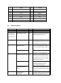
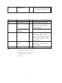
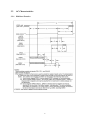
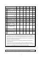
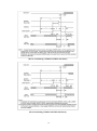
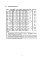
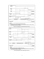
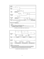
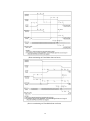
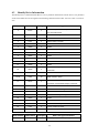
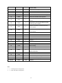
PIO timing parameters
t0
Cycle time
t1
Address valid to
(min)
DIOR-/DIOW- setup
(min)
t2
DIOR-/DIOW-
(min)
t2i
DIOR-/DIOW- recovery time
Mode 0
Mode 1
Mode2
Mode 3
Mode 4
Note
ns
ns
ns
ns
ns
600
383
240
180
120
70
50
30
30
25
165
125
100
80
70
1
--
--
--
70
25
1
1,4
(min)
t3
DIOW- data setup
(min)
60
45
30
30
20
t4
DIOW- data hold
(min)
30
20
15
10
10
t5
DIOR- data setup
(min)
50
35
20
20
20
t6
DIOR- data hold
(min)
5
5
5
5
5
t6z
DIOR- data tristate
(max)
30
30
30
30
30
2
t9
DIOR-/DIOW- to address
20
15
10
10
10
10
0
0
0
0
0
35
35
35
35
35
1250
1250
1250
1250
1250
5
5
5
5
5
valid hold
tRD
(min)
Read Data Valid to IORDY
active (if IORDY initially low
after tA)
(min)
tA
IORDY Setup time
tB
IORDY Pulse Width
tC
IORDY assertion to release
(max)
3
(max)
Notes1.
t0 is minimum total cycle, t2 is minimum DIOR-/DIOW- assertion time, and t2i is the minimum
DIOR-/DIOW- negation time. A host implementation shall lengthen t2i to ensure that t0 is equal to or
greater than the value reported in the devices IDENTIFY DEVICE data. A device implementation
shall support any length host implementation.
2.
This parameter specifies the time from the negation edge of DIOR- to the time that the data is
released by the device.
3.
The delay from the activation of FIOR- or DIOW- until the state of IORDY is first sampled. If
IORDY is inactive then the host shall wait until IORDY is active before the PIO cycle is complete. If
the device is not driving IORDY negated at the tA after the activation of DIOR-
or DIOW-, that t5 shall be met and tRD is not applicable. If the device is driving IORDY
9