Transcript
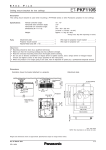
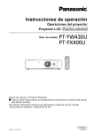
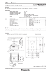
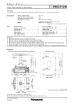
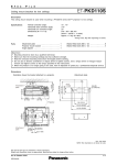
S P E F C I L E ET-PKF110H Ceiling mount bracket for high ceilings D escription This ceiling mount bracket is used when mounting a PT-FW430 series or other Panasonic projector to high ceilings. Specifications Vertical correction angle: Horizontal slant correction angle: Horizontal turn correction angle: Dimensions (W × H × D): +5°, -20° ±10° ±5° 313 × 309– 389 × 222 mm (12-5/16˝ × 12-5/32˝–15-5/16˝ × 8-3/4˝ ) Approx. 2.3 kg* (5.1 lbs*) Weight: * Average value. May differ depending on models. Parts Attachment plate . . . . . Projector mount bracket Adjuster pole A . . . . . . . Adjuster pole B . . . . . . . Angle adjuster A . . . . . . Angle adjuster B . . . . . . . . . . . . . . . . . . . . . . . . . . . . . . . . . . . . . . . . . . . . . . . . . . . . . . . . . . . . . . . . . . . . . . . . . . . . . . . . . . . . . . . . . . . . . . . . . . . . . . . . . . . . . . . . . . . . . . . . 1 1 1 1 1 1 Washer-fitted Washer-fitted Wire rope for Wire rope for hexagonal bolts (M6 × 12) screws (M4 × 10) . . . . . . projector mount bracket . projector unit . . . . . . . . . ... .... .... .... . . . . . . . . 19 . 4 . 1 . 1 Caution: • Mounting should be done by a qualified technician. • Make sure that the mounting (ceiling) area has sufficient strength. • Read the enclosed mounting instructions thoroughly before starting. • Do not use an electric screwdriver or impact driver to tighten screws. Use a torque driver or hexagon torque wrench and tighten screws to the torque specified in the instructions. • When the product is no longer going to be used, have it disposed of quickly by a professional disposal service. Dimensions 130 ( 5-1/8 ) 100 ( 3-15/16 ) 150 ( 5-29/32) ∅42 (1-21/32) 3-∅9.5 ( ∅3/8 ) Adjustable in 20 mm ( 25/32) steps Attachement plate ∅49 (1-15/16 ) 424– 504 (16-11/16 –19-27/32) Adjustable in 20 mm ( 25/32) steps 10 ° 10 13 (1/2)* ° 175 ( 6-7/8 ) Attachment plate ° 20 5° 369 – 449 (14-17/32–17-11/16 ) Illustration shows the bracket attached to a projector. 194 (7-5/8 ) Projector 430 (16-15/16 ) ∅8.5 ( ∅11/32) 110 (4-11/32) 70 ( 2-3/4) 140 ( 5-1/2) * From c e nte r of rot ation to c e nte r of le ns 20 ( 2-9/16 ) 65 ( 2-9/16 ) 160 ( 6-5/16 ) unit : mm (inch) NOTE: This illustration is not drawn to scale. Weights and dimensions shown are approximate. Specifications subject to change without notice. As of July 2011 SFL11A003-1 1/1