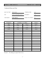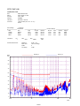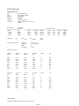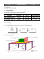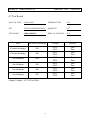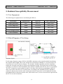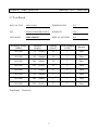
1
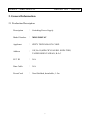
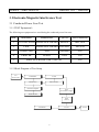
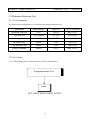
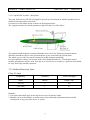
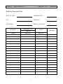
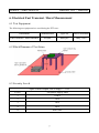
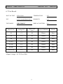
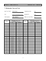
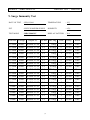
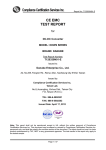
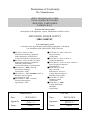
Declaration of Conformity
We, Manufacturer
ZIPPY TECHNOLOGY CORP.
10F,No.50,MIN CHYUAN RD.
SHIN-TIEN, TAIPEI HSIEN
TAIWAN, R.O.C.
declare that the product
(description of the apparatus, system, installation to which it refers)
SWITCHING POWER SUPPLY
MRG-5800V4V
is in conformity with
(reference to the specification under which conformity is declared)
i in accordance with 2004/108/EC-EMC Directive
▓EN 55022 : 2006+A1/2007
Information technology equipment
-Radio disturbance characteristics
-Limits and methods of measurement
▓EN 55024 : 1998+A1/2001+A2/2003
Information technology equipment
-Immunity characteristics
-Limits and methods of measurement
▓EN 61000-4-2 : 2009 Criteria B
Electrostatic discharge
requirements "ESD"
▓EN 61000-4-3 : 2006+A1/2008 Criteria A
Radiated, radio frequency
electromagnetic field
▓EN 61000-4-4 : 2004 Criteria B
Electrical fast transient
requirements "EFT"
▓EN 61000-4-5 : 2006 Criteria B
Surge Immunity
requirements
▓EN 61000-4-6 : 2007 Criteria A
Conducted Immunity
▓EN 61000-4-8 : 1993+A1/2001 Criteria A
Power Frequency Magnetic
Field Immunity
▓EN 61000-4-11 : 2004
Dip Criteria B
Interruptions Criteria C
Voltage Dip,interruptions
Immunity requirements
▓EN 61000-3-2 : 2006
Harmonic current
requirements
▓EN 61000-3-3 : 2008
Voltage fluctuations
and flicker
requirements
Manufacturer
Date :
SEP,02,2010
Signature:
Name:
Test-Lab
Date :
SEP,02,2010
Signature:
ZIPPY
Name:
ZIPPY
MODEL : MRG-5800V4V
REPORT NO. : 10090203
APPLICATION FOR CERTIFICATION
ON Behalf Of
ZIPPY TECHNOLOGY CORP.
SWITCHING POWER SUPPLY
Model# : MRG-5800V4V
FCCID:N/A
PREPARED FOR:
ZIPPY TECHNOLOGY CORP.
10F,No.50,MIN CHYUAN RD.
SHIN-TIEN, TAIPEI HSIEN
TAIWAN, R.O.C
REPORT BY:
ZIPPY TECHNOLOGY CORP.
10F,No.50,MIN CHYUAN RD.
SHIN-TIEN, TAIPEI HSIEN
TAIWAN, R.O.C
TEL: (02)2918-8512
FAX:(02)2913-4969
2
MODEL : MRG-5800V4V
REPORT NO. : 10090203
TABLE OF CONTENTS
Description
Page
1. Test Report Certification…………………………………………………………….. 5
2. General Information………………………………………………………………….. 6
2.1 Production Description………………………………………………………………….…….. 6
2.2 Tested System Details……………………………………………………………….………... 7
2.2.1 Resistor Load…………………………………………………………………………….. 7
2.3 Test Methodology…………………………………………………………………………….. 7
2.4 Test Facility……………………………………………………………………………………. 7
3. Electronic-Magnetic Interference Test………………………………….…..…... 8
3.1. Conducted Power Line Test……………………………………………………………..….. 8
3.1.1 Test Equipments…………………………………………………………………………. 8
3.1.2 Block Diagram of Test Setup…………………………………………………………… 8
3.1.3 Conducted Powerline Emission Limit…………………………………………………. 9
3.1.4 EUT Configuration on Measurement…………………………………………………… 9
3.1.5 EUT Exercise Software…………………………………………………………….……. 9
3.1.6 Conducted Emission Data………………………………………………………….……. 9
3.2. Radiation Emission Test .........................................................……….............………… 11
3.2.1 Test Equipment ....................................................................……...............………... 11
3.2.2 Test Setup ...........................................................……................................………... 11
3.2.3 Radiated Emission Limited ....................................…….............................……….. 12
3.2.4 EUT Configuration ...................................................……..........................………... 13
3.2.5 Operating Condition of EUT .......................................…….......................………... 13
3.2.6 Radiated Emission Data .....................................................…….................……….. 13
3.2.7 Test Photo and Setup ..................................................…….................……………. 13
4. ESD Measurement…………………………………………………………………….. 17
4.1 Test Equipments……………………………………………………………………………….. 17
4.2 Test Setup………………………………………………………………………………….…… 17
4.2.1 Block Diagram of Connections between EUT and simulators………………………. 17
4.2.2 Test Setup of EUT…………………………………………………………………….….. 17
4.3 Severity Levels………………………………………………………………………………… 18
4.4 EUT Operating Condition…………………………………………………………………….. 18
4.5 Test Procedure………………………………………………………………………….……… 18
4.6 Test Method…………………………………………………………………….……….…….. 18
4.7 Test Result…………………………………………………………………………………….. 19
3
MODEL : MRG-5800V4V
REPORT NO. : 10090203
TABLE OF CONTENTS
Description
Page
5. Radiated Susceptibility Measurement……………………………………………. 20
5.1 Test Equipment…………………………………………………………………………….…... 20
5.2 Block Diagram of Test Setup………………………………………………………………… 20
5.3 Severity Levels………………………………………………………………………….…….. 21
5.4 EUT Operating Condition…………………………………………………………………….. 21
5.5 Test procedure…………………………………………………………………….…….…….. 21
5.6 Test Method……………………………………………………………………………….…… 21
5.7 Test Result…………………………………………………………………………………….. 22
6.Electrical Fast Transient/Burst Measurement……………...………………….. 23
6.1 Test Equipment …………………………………………………………………………….… 23
6.2 Block Diagram of Test Setup………………………………………………………………… 23
6.3 Severity Levels ……………………………………………………………………………….. 23
6.4 EUT Operating Condition……………………………………………………………………. 24
6.5 Test procedure ……………………………………………………………………….……….. 24
6.6 Test Method……………………………………………………………………………………. 24
6.7 Test Result…………………………………………………………………………………….. 25
7. Harmonic Current Requirements…………………………………………………
8. Voltage Fluctuation and Filcker Test……………………………………………..
9. Surge Immunity Test………………………………………………………………….
10. Conducted Immunity Test………………………………………………………….
11. Voltage Dip,interruptions Immunity Test……………………………………...
12. Photographs……………………………………………………………………………
13. EMI Reduction method during compliance Testing…………………………
Appendix A Circuit diagram, block diagram, User Manual
Appendix B Doc
4
26
29
30
31
32
33
39
MODEL : MRG-5800V4V
REPORT NO. : 10090203
1. Test Report Certification
Applicant
: ZIPPY TECHNOLOGY CORP.
Manufacturer
: ZIPPY TECHNOLOGY CORP.
EUT Description
: Switching Power Supply
(A) FCC ID
:
N/A
(B) Model No.
:
MRG-5800V4V
(C) Serial No.
:
N/A
(D) Power Supply
:
115Vac/60Hz,230Vac/50Hz
MEASUREMENT PROCEDURE USED :
EN 55024 RULES
EN 55022 RULES
THE DEVICE DESCRIBED ABOVE WAS TESTED BY ZIPPY SHIN JIUH CORP. TO
DETERMINE THE SEVERITY LEVELS THE DEVICE CAN ENDURE AND ITS
PERFORMANCE CRITERION.
THE MEASUREMENT RESULTS ARE CONTAINED IN THIS TEST REPORT AND
ZIPPY SHIN JIUH CORP. IS ASSUMED FULL RESPONSIBILITY FOR THE
ACCURACY AND COMPLETENESS OF THESE MEASUREMENT.
ALSO, THIS REPORT SHOWS THAT THE EUT TO BE TECHNICALLY COMPLIANT
WITH THE EN STANDARD.
Test Dated
:
Test Engineer
:
Approve & Authorized Signer
:
5
SEP,02,2010
a
MODEL : MRG-5800V4V
REPORT NO. : 10090203
2. General Information
2.1 Production Description
Description
: Switching Power Supply
Model Number
: MRG-5800V4V
Applicant
: ZIPPY TECHNOLOGY CORP.
Address
:
FCC ID
: N/A
Data Cable
: N/A
PowerCord
: Non-Shielded, detachable, 1.5m
10F,No.50,MIN CHYUAN RD. SHIN-TIEN,
TAIPEI HSIEN TAIWAN, R.O.C
6
MODEL : MRG-5800V4V
REPORT NO. : 10090203
2.2 Tested System Details
The FCC IDs for all equipment, plus descriptions of all cables used in the tested system
(including inserted cards, which have grants) are:
2.2.1 Resistor Load
Model Number
: ELECTRONIC LOAD
Serial Number
:
N/A
FCC ID
:
N/A
Manufacturer
: ZIPPY
Power
: 800W
2.3 Test Methodology
EMI Test:
Both conducted and radiated testing were performed according to the procedures in EN 55022
Radiated testing was performed at an antenna to EUT distance of 10 meters.
EMS Test:
Performed according to procedures in EN 61000 series regulations.
2.4 Test Facility
ZIPPY TECHNOLOGY CORP.
10F,No.50,MIN CHYUAN RD.
SHIN-TIEN, TAIPEI HSIEN
TAIWAN, R.O.C
7
MODEL : MRG-5800V4V
REPORT NO. : 10090203
3. Electronic-Magnetic Interference Test
3.1 Conducted Power Line Test
3.1.1 TEST Equipment's
The following test equipment's are used during the conducted power line tests:
Item
1
Instrument
Manufacture
Type No:
Last Calibration
TEST RECEIVER ROHDE & SCHWARZ ESHS10
2
LISN
3
COMPUTER
Acer
Power8000
N/A
4
PRINTER
EPSON
5700L
N/A
5
ROHDE & SCHWARZ ENV4200
Mar.,2010
SHIELDED ROOM 4.0M*3.0M*3M
Jan.,2010
N/A
3.1.2 Block Diagram of Test Setup
TO
Power Line
Transformer
L.I.S.N
Test Receive
Pulse Limiter
Personal Computer
EUT
Switch Power Supply
Printer/Plotter
Load
(Active)
Terminator
L.I.S.N
8
AC IN
MODEL : MRG-5800V4V
REPORT NO. : 10090203
3.1.3 Conducted Powerline Emission Limit
Maximum RF Line Voltage dB(uV)
Frequency
Class B
MHz
QUASI-PEAK
AVERAGE
0.15 - 0.50
66-56
66-56
0.50 - 5.0
56
56
5.0 - 30
60
60
Remarks : In the Above Table, the tighter limit applies at the band edges.
3.1.4 EUT Configuration on Measurement
The equipment's which is listed 3.2 are installed on Conducted Power Line Test to meet the
Commission requirement and operating in a manner which tends to maximize its emission
characteristics in a normal application.
3.1.5 EUT Exercise Software
The EUT exercise program used during conducted testing was designed to exercise the EUT in a
manner similar to a typical use. The exercise sequence is listed as below :
3.1.5.1 Setup the EUT and simulators as shown on 3.2.
3.1.5.2 Turn on the power of all equipment's.
3.1.6 Conducted Emission Data
The measurement range of conducted emission which is from 0.15 MHz to 30 MHz was
investigated. The initial step in collecting conducted data is a spectrum analyzer peak scan of the
measurement range for all the test modes. Then the worst modes were reported the following data
pages.
9
MODEL : MRG-5800V4V
REPORT NO. : 10090203
Conducted Emission Data
DATE OF TEST : SEP,02,2010
TEMPERATURE
:26℃
:65%
EUT
: SWITCH POWER SUPPLY
HUMIDITY
TEST MODE
: MRG-5800V4V
DISPLAY PATTERN :N/A
Frequency
Reading Level dBuV
Limites
MHz
Line 1
Line 2
DBuV
0.206
54.01
53.34
63.37
0.344
46.91
45.85
59.11
29.95
41.85
43.72
60.00
Remark:All readings are Quasi-Peak values.
10
ZIPPY EMC LAB
conduction test
EUT:
Manuf:
Op Cond:
Operator:
Test Spec:
Comment:
Scan Settings
Start
150kHz
500kHz
5MHz
Transducer
MRG-5800V4V SPS
ZIPPY TECH CO..LTD
FULL LOAD
EDMENT
EN 55022-- Class B
Load Condition( 50 21 0.8 19 3.5 )
L220V
(3 Ranges)
Frequencies
Stop
500kHz
5MHz
30MHz
No.
1
Prescan Measurement:
Step
2kHz
20kHz
50kHz
Start
IF BW
10kHz
10kHz
10kHz
Stop
9kHz
Detectors:
Meas Time:
Peaks:
Acc Margin:
Detector
QP+AV
QP+AV
QP+AV
Receiver Settings
M-Time
Atten
1msec
Auto
1msec
Auto
1msec
Auto
Preamp
OFF
OFF
OFF
OpRge
60dB
60dB
60dB
Name
CEB
30MHz
X QP / + AV
see scan settings
8
25 dB
EN_QP_B
dBµV
100
EN_AV_B
90
80
70
60
50
40
30
20
10
0
0.15
1.0
10.0
30.0
MHz
PAGE 1
ZIPPY EMC LAB
conduction test
EUT:
Manuf:
Op Cond:
Operator:
Test Spec:
Comment:
MRG-5800V4V SPS
ZIPPY TECH CO..LTD
FULL LOAD
EDMENT
EN 55022-- Class B
Load Condition( 50 21 0.8 19 3.5 )
L220V
Scan Settings
(3 Ranges)
Frequencies
Stop
500kHz
5MHz
30MHz
Start
150kHz
500kHz
5MHz
Transducer
No.
1
Prescan Measurement:
Step
2kHz
20kHz
50kHz
Start
IF BW
10kHz
10kHz
10kHz
Stop
9kHz
Detectors:
Meas Time:
Peaks:
Acc Margin:
Detector
QP+AV
QP+AV
QP+AV
Receiver Settings
M-Time
Atten
1msec
Auto
1msec
Auto
1msec
Auto
Name
CEB
30MHz
X QP / + AV
see scan settings
8
25 dB
Peak Search Results
Frequency
MHz
QP Level
dBµV
0.206
0.276
0.344
0.414
0.482
29.2
29.75
29.95
54.01
49.28
46.91
44.13
42.46
41.76
44.58
41.85
Frequency
MHz
AV Level
dBµV
0.206
0.276
0.344
0.412
0.482
0.488
18.85
19.25
49.40
45.08
42.73
41.15
40.13
37.08
39.86
39.51
QP Limit
dBµV
63.37
60.94
59.11
57.57
56.30
60.00
60.00
60.00
AV Limit
dBµV
53.37
50.94
49.11
47.61
46.30
46.20
50.00
50.00
QP Delta
dB
Phase
-
PE
-
9.36
11.66
12.20
13.44
13.84
18.24
15.42
18.15
N
N
N
N
N
N
N
N
gnd
gnd
gnd
gnd
gnd
gnd
gnd
gnd
AV Delta
dB
Phase
-
PE
-
3.97
5.86
6.38
6.46
6.17
9.12
10.14
10.49
N
N
N
N
N
N
N
N
gnd
gnd
gnd
gnd
gnd
gnd
gnd
gnd
* limit exceeded
Indicated Phase/PE shows Configuration of max. Emission
PAGE 2
Preamp
OFF
OFF
OFF
OpRge
60dB
60dB
60dB
ZIPPY EMC LAB
conduction test
EUT:
Manuf:
Op Cond:
Operator:
Test Spec:
Comment:
Scan Settings
Start
150kHz
500kHz
5MHz
Transducer
MRG-5800V4V SPS
ZIPPY TECH CO..LTD
FULL LOAD
EDMENT
EN 55022-- Class B
Load Condition( 50 21 0.8 19 3.5 )
N220V
(3 Ranges)
Frequencies
Stop
500kHz
5MHz
30MHz
No.
1
Prescan Measurement:
Step
2kHz
20kHz
50kHz
Start
IF BW
10kHz
10kHz
10kHz
Stop
9kHz
Detectors:
Meas Time:
Peaks:
Acc Margin:
Detector
QP+AV
QP+AV
QP+AV
Receiver Settings
M-Time
Atten
1msec
Auto
1msec
Auto
1msec
Auto
Preamp
OFF
OFF
OFF
OpRge
60dB
60dB
60dB
Name
CEB
30MHz
X QP / + AV
see scan settings
8
25 dB
EN_QP_B
dBµV
100
EN_AV_B
90
80
70
60
50
40
30
20
10
0
0.15
1.0
10.0
30.0
MHz
PAGE 1
ZIPPY EMC LAB
conduction test
EUT:
Manuf:
Op Cond:
Operator:
Test Spec:
Comment:
MRG-5800V4V SPS
ZIPPY TECH CO..LTD
FULL LOAD
EDMENT
EN 55022-- Class B
Load Condition( 50 21 0.8 19 3.5 )
N220V
Scan Settings
(3 Ranges)
Frequencies
Stop
500kHz
5MHz
30MHz
Start
150kHz
500kHz
5MHz
Transducer
No.
1
Prescan Measurement:
Step
2kHz
20kHz
50kHz
Start
IF BW
10kHz
10kHz
10kHz
Stop
9kHz
Detectors:
Meas Time:
Peaks:
Acc Margin:
Detector
QP+AV
QP+AV
QP+AV
Receiver Settings
M-Time
Atten
1msec
Auto
1msec
Auto
1msec
Auto
Name
CEB
30MHz
X QP / + AV
see scan settings
8
25 dB
Peak Search Results
Frequency
MHz
QP Level
dBµV
0.206
0.274
0.344
0.412
0.48
29.4
29.6
29.95
53.34
48.44
45.85
43.08
40.97
42.42
41.45
43.72
Frequency
MHz
AV Level
dBµV
0.206
0.276
0.342
0.348
0.41
0.478
0.484
19.45
49.00
43.95
42.05
39.68
39.41
37.08
36.15
40.15
QP Limit
dBµV
63.37
61.00
59.11
57.61
56.34
60.00
60.00
60.00
AV Limit
dBµV
53.37
50.94
49.15
49.01
47.65
46.37
46.27
50.00
QP Delta
dB
Phase
-
PE
-
10.03
12.56
13.26
14.53
15.37
17.58
18.55
16.28
N
N
N
N
N
N
N
N
gnd
gnd
gnd
gnd
gnd
gnd
gnd
gnd
AV Delta
dB
Phase
-
PE
-
4.37
6.99
7.10
9.33
8.24
9.29
10.12
9.85
N
N
N
N
N
N
N
N
gnd
gnd
gnd
gnd
gnd
gnd
gnd
gnd
* limit exceeded
Indicated Phase/PE shows Configuration of max. Emission
PAGE 2
Preamp
OFF
OFF
OFF
OpRge
60dB
60dB
60dB
MODEL : MRG-5800V4V
REPORT NO. : 10090203
3.2 Radiation Emission Test
3.2.1 Test Equipment
The following test equipment's are used during the radiated emission test :
Instrument
Manufacture
Type No:
Spectrum Analyzer
H.P
8594A
May.,2010
Test Receiver
IFR System
A-7550
Jun.,2010
Preamplifier
H.P
8447D
May.,2010
Biconical Ant.
Emco
3110
Jun.,2010
Log-Periodic Ant.
Emco
3146
Jun.,2010
Dipole Antenna
Emco
3121C
May.,2010
3.2.2 Test Setup
3.2.2.1 Block Diagram of Connection between EUT and simulators
Equipment under Test
Load
EUT: SWITCHING POWER SUPPLY
11
Last Calibration
MODEL : MRG-5800V4V
REPORT NO. : 10090203
3.2.2.2 Open Field Test Site - description
The open field test site (OFTS) is designed to provide an environment in which repeatable tests of
radiated emissions can be carried out.
It consists of a flat elliptical area as shown in the diagram below.
The equipment under test and the antenna are placed at the foci of the ellipse.
The antenna height should be remotely adjustable from 1m to 4m. Measuring instrumentation
should be outside the ellipse at the position shown or in a room under the ground plane.
The whole or part of the site may be enclosed in an RF transparent building.
For precompliance testing a 3m test site with a fixed height antenna (at 1.5-2m height) and no
metallic ground plane may be used. This may be a clear area on a car park or a grass area but should
be away from large metallic structures.
3.2.3 Radiated Emission Limit
Class A Limits
Frequency
Distance
Field Strength
MHz
Meter
DB(uV/M)
30-230
3
50
230-1000
3
57
Remarks :
1. The tighter limit shall apply at the edge between two frequency bands.
2. Distance refers to the distance in meters between the measuring instrumentantenna and the
closed point of any part of the device or system.
12
MODEL : MRG-5800V4V
REPORT NO. : 10090203
3.2.4 EUT Configuration
The equipment's which is listed 4.2.1 are installed on Radiated Emission Test to meet the
Commission requirement and operating in a manner which tends to maximize its emission
characteristics in a normal application.
3.2.5 Operation Condition of EUT
Same as Conducted Power Line Test which is listed in 3.1.5 .
3.2.6 Radiated Emission Data
The measurement range of radiated emission which is from 30 MHz to 1000 MHz was investigated.
The initial step in collecting conducted data is a spectrum analyzer peak scan of the measurement
range for all the test modes. Then the worst modes were reported the following data pages.
3.2.7 Test Photo and Setup
※During the radiated test, the power-supply has to test with chassis, which is not allowed to be
operated stand-alone. (For user, final assembly has to comply with corresponding EMC-and
safety-regulations.)
13
MODEL : MRG-5800V4V
REPORT NO. : 10090203
Radiated Emission Data
DATE OF TEST :
TEMPERATURE
:
:
EUT
:
HUMIDITY
TEST MODE
:
DISPLAY PATTERN :
Frequency
(MHz)
Emission Level
Horizontal
dBuV/m
14
Limits
dBuV/m
Remark
MODEL : MRG-5800V4V
REPORT NO. : 10090203
Radiated Emission Data
DATE OF TEST :
TEMPERATURE
:
:
EUT
:
HUMIDITY
TEST MODE
:
DISPLAY PATTERN :
Frequency
(MHz)
Emission Level
Vertical
dBuV/m
15
Limits
dBuV/m
Remark
MODEL : MRG-5800V4V
REPORT NO. : 10090203
Horizontal Curve
Vertical Curve
16
MODEL : MRG-5800V4V
REPORT NO. : 10090203
4. ESD Measurement
4.1 Test Equipment
The following test equipment's are used during the ESD test :
Instrument
Manufacture
Type No:
Last Calibration
ESD Simulator system
Keytek
MZ-15/EC
May.,2010
Electronic Load
D-RAM
Load-2000
N/A
4.2 Test Setup
4.2.1 Block Diagram of Connections between EUT and simulators
ESD
Simulator
system
EUT
4.2.2 Test Setup of EUT
17
Load
MODEL : MRG-5800V4V
REPORT NO. : 10090203
4.3 Severity Levels
LEVEL
TEST VOLTAGE CONTACT
DISCHARGE
TEST VOLTAGE AIR
DISCHARGE
1
2KV
2KV
2
4KV
4KV
3
6KV
6KV
4
8KV
8KV
X
SPECIAL
SPECIAL
4.4 EUT Operating Condition
1. Setup the EUT and Test Equipment as shown on 4.2
2. power on.
4.5 Test Procedure
Air Discharge:
This test was done above a non-conductive surfaces. The round discharge electrode about 30cm
away will approach as fast as possible to touch test points of the EUT.
Discharge happens before the contact. This procedure is repeated ten times on one selected location.
4.6 Test Method
According to IEC 61000-4-2
18
MODEL : MRG-5800V4V
REPORT NO. : 10090203
4.7 Test Result
DATE OF TEST : SEP,02,2010
TEMPERATURE
:26℃
:65%
EUT
: SWITCH POWER SUPPLY
HUMIDITY
TEST MODE
: MRG-5800V4V
DISPLAY PATTERN :N/A
Item
Amount of discharge
Contact discharge
500
Contact discharge
500
Air discharge
500
Air discharge
500
Air discharge
500
Air discharge
500
※Input Voltage : AC 230Vac/50Hz
19
Voltage
Results
+2KV
-2KV
+4KV
-4KV
+2KV
-2KV
+4KV
-4KV
+6KV
-6KV
+8KV
-8KV
Pass
Pass
Pass
Pass
Pass
Pass
Pass
Pass
Pass
Pass
Pass
Pass
MODEL : MRG-5800V4V
REPORT NO. : 10090203
5. Radiated Susceptibility Measurement
5.1 Test Equipment
The following test equipment's are used during the RS test :
Instrument
Manufacture
Type No:
Last Calibration
Signal generator
H.P
8657A
Dec.,2009
Power amplifier
A&R
100A100
Dec.,2009
Field strength meter
A&R
FM2000
Oct.,2009
Field strength sensor
A&R
EP2000
Oct.,2009
Power antenna
A&R
AT1080
Oct.,2009
5.2 Block Diagram of Test Setup
Antennas-layout
For the upper frequency range of 200 to 1000 MHz, antennas are the normal method of producing
the required field strength. This is also carried out in an anechoic chamber or a screened room. If a
screened room is used it must be damped . The anechoic chamber should be used for compliance
testing, the screened room may be used for precompliance testing. The fields in the screened room
will not be as uniform as those obtainable in an anechoic chamber and will also not be as repeatable.
The EUT is placed on a non-conductive table, 0.8 m above the reference ground plane, which in
many cases will be the floor of a screened room. According to the standards, the EUT should be
oriented so that its most sensitive side is facing the antenna. In practice it can be difficult to decide
beforehand which is the most sensitive side, and in most cases, a series of tests will be required with
the EUT in several orientations.
20
MODEL : MRG-5800V4V
REPORT NO. : 10090203
5.3 Severity Levels
LEVEL
FIELD STRENGTH V/M
1
1
2
3
3
10
X
SPECIAL
5.4 EUT Operating Condition
Same as section 4.4.
5.5 Test Procedure
The EUT and load are placed on a table which is 0.8 meter above ground. The field sensor is
also placed on the same table to monitor field strength from transmitting antenna.
EUT is set 1 meter away from the transmitting antenna which is mounted on an antenna each
time.
The antenna is fixed 1 meter above ground. Both horizontal and vertical polarization of the
antenna are set on measurement. In order to judge the EUT performance, a CCD camera is
used to monitor EUT screen.
All the scanning conditions are as follows :
Condition of Test
1. Field Strength
2. Radiated Signal
3. Scanning Frequency
4. Sweep Time of Radiated
Remarks
3 V/M Level 2
80% Amplitude Modulated with a 1KHz Tone
80 MHz-1 GHz
0.0015 Decade/s
5.6 Test Method
According to IEC 61000-4-3
21
MODEL : MRG-5800V4V
REPORT NO. : 10090203
5.7 Test Result
DATE OF TEST : SEP,02,2010
TEMPERATURE
:26℃
:65%
EUT
: SWITCH POWER SUPPLY
HUMIDITY
TEST MODE
: MRG-5800V4V
DISPLAY PATTERN :N/A
Frequency Range
(MHz)
Position
(Angle)
Polarity
(HorV)
Field Strength
(V/M)
Results
80-1000
0∘ (Front)
H
3
Pass
80-1000
90∘ (Right)
H
3
Pass
80-1000
180∘ (Back)
H
3
Pass
80-1000
270∘ (Left)
H
3
Pass
80-1000
0∘ (Front)
V
3
Pass
80-1000
90∘ (Right)
V
3
Pass
80-1000
180∘ (Back)
V
3
Pass
80-1000
270∘ (Left)
V
3
Pass
Test Result:Criteria A
22
MODEL : MRG-5800V4V
REPORT NO. : 10090203
6. Electrical Fast Transient / Burst Measurement
6.1 Test Equipment
The following test equipment's are used during the EFT tests :
Instrument
Manufacturer
Type No.
Last Calibration
Fast Transient / Burst enerator
Keytek
EMCpro
May.,2010
6.2 Block Diagram of Test Setup
6.3 Severity Levels
Open Circuit Output Test Voltage +/- 10%
Level
On power supply lines
1
0.5KV
2
1KV
3
2KV
4
4KV
X
SPECIAL
23
MODEL : MRG-5800V4V
REPORT NO. : 10090203
6.4 EUT Operation Condition
Same as section 4.4.
6.5 Test Procedure
The EUT and its load are placed on a table which is 0.8 meter above a metal ground plane
measured 1m*1m min. And 0.65 mm thick min. And projected beyond the EUT by at least
0.1m on all sides.
The EUT is away from the walls of the test AC power line test is as follows:
For Ac power line test:
The EUT is connected to the power mains through a coupling device that directly couples the
EFT interference signal.
Each of the Line and Neutral conductor is impressed with burst noise for 1 min.
6.6 Test Method
According to IEC 61000-4-4.
24
MODEL : MRG-5800V4V
REPORT NO. : 10090203
6.7 Test Result
DATE OF TEST : SEP,02,2010
TEMPERATURE
:26℃
:65%
EUT
: SWITCH POWER SUPPLY
HUMIDITY
TEST MODE
: MRG-5800V4V
DISPLAY PATTERN :N/A
Inject Line
Voltage KV
Inject time
(sec)
Inject Method
Result
L1
+/-1
60
Direct
Pass
L2
+/-1
60
Direct
Pass
PE
+/-1
60
Direct
Pass
L1-L2
+/-1
60
Direct
Pass
L1-PE
+/-1
60
Direct
Pass
L2-PE
+/-1
60
Direct
Pass
L1,L2-PE
+/-1
60
Direct
Pass
※Input Voltage : AC 230Vac/50Hz
25
MODEL : MRG-5800V4V
REPORT NO. : 10090203
7. Harmonic Current Test
DATE OF TEST : SEP,02,2010
TEMPERATURE
:26℃
:65%
EUT
: SWITCH POWER SUPPLY
HUMIDITY
TEST MODE
: MRG-5800V4V
DISPLAY PATTERN :N/A
Item
1
3
5
7
9
11
13
15
17
19
21
23
25
27
29
31
33
35
37
39
Reading Leve A
A
Limites
4.153
0.447
0.146
0.054
0.030
0.014
0.013
0.011
0.009
0.008
0.006
0.005
0.003
0.002
0.001
0.001
0.003
0.003
0.004
0.004
Item
2.300
1.140
0.770
0.400
0.330
0.210
0.150
0.132
0.118
0.107
0.098
0.090
0.083
0.078
0.073
0.068
0.064
0.061
0.058
26
Reading Leve A
A
Limites
MODEL : MRG-5800V4V
REPORT NO. : 10090203
27
MODEL : MRG-5800V4V
REPORT NO. : 10090203
28
MODEL : MRG-5800V4V
REPORT NO. : 10090203
8. Voltage Fluctuation And Flicker Test
DATE OF TEST : SEP,02,2010
TEMPERATURE
:26℃
:65%
EUT
: SWITCH POWER SUPPLY
HUMIDITY
TEST MODE
: MRG-5800V4V
DISPLAY PATTERN :N/A
Item
Reading
Limit
Result
Pst
0.000
1.00
Pass
P1t
0.000
0.65
Pass
Dc (%)
0.000
3.00
Pass
Dmax (%)
0.000
4.00
Pass
Dt (%)
0.000
0.20
Pass
29
MODEL : MRG-5800V4V
REPORT NO. : 10090203
9. Surge Immunity Test
DATE OF TEST : SEP,02,2010
TEMPERATURE
:26℃
:65%
EUT
: SWITCH POWER SUPPLY
HUMIDITY
TEST MODE
: MRG-5800V4V
DISPLAY PATTERN :N/A
Wavefor Voltage
Output:LC
Phs Ref Phs Ang
Tests
Delay
Result
12 Ohm -2000V MAINS:L1/PE
L1
0 deg.
5
60 sec
Pass
12 Ohm -2000V MAINS:L1/PE
L1
90 deg.
5
60 sec
Pass
12 Ohm -2000V MAINS:L1/PE
L1
270 deg.
5
60 sec
Pass
12 Ohm
2000V MAINS:L1/PE
L1
0 deg.
5
60 sec
Pass
12 Ohm
2000V MAINS:L1/PE
L1
90 deg.
5
60 sec
Pass
12 Ohm
2000V MAINS:L1/PE
L1
270 deg.
5
60 sec
Pass
12 Ohm -2000V MAINS:L2/PE
L1
0 deg.
5
60 sec
Pass
12 Ohm -2000V MAINS:L2/PE
L1
90 deg.
5
60 sec
Pass
12 Ohm -2000V MAINS:L2/PE
L1
270 deg.
5
60 sec
Pass
12 Ohm
2000V MAINS:L2/PE
L1
0 deg.
5
60 sec
Pass
12 Ohm
2000V MAINS:L2/PE
L1
90 deg.
5
60 sec
Pass
12 Ohm
2000V MAINS:L2/PE
L1
270 deg.
5
60 sec
Pass
2 Ohm
-1000V MAINS:L1/L2
L1
0 deg.
5
60 sec
Pass
2 Ohm
-1000V MAINS:L1/L2
L1
90 deg.
5
60 sec
Pass
2 Ohm
-1000V MAINS:L1/L2
L1
270 deg.
5
60 sec
Pass
2 Ohm
1000V MAINS:L1/L2
L1
0 deg.
5
60 sec
Pass
2 Ohm
1000V MAINS:L1/L2
L1
90 deg.
5
60 sec
Pass
2 Ohm
1000V MAINS:L1/L2
L1
270 deg.
5
60 sec
Pass
30
MODEL : MRG-5800V4V
REPORT NO. : 10090203
10. Conducted Immunity Test
DATE OF TEST : SEP,02,2010
TEMPERATURE
:26℃
:65%
EUT
: SWITCH POWER SUPPLY
HUMIDITY
TEST MODE
: MRG-5800V4V
DISPLAY PATTERN :N/A
Frequency Range
(MHz)
Polarity
(HorV)
Field Strength
(V/M)
Results
0.15-80
H
3
Pass
INJECTION TYPE:DIRECT CDN Type M3
TEST CONDITION:Step:1% Dwell Time : 3sec
Test result:Criteria A
31
MODEL : MRG-5800V4V
REPORT NO. : 10090203
11. Voltage Dip, Interruptions Immiunity Test
DATE OF TEST : SEP,02,2010
TEMPERATURE
:26℃
:65%
EUT
: SWITCH POWER SUPPLY
HUMIDITY
TEST MODE
: MRG-5800V4V
DISPLAY PATTERN :N/A
Test
Voltage
AC 115V
AC 230V
Phase Reduction Duration
%
Angle
(Periods)
0 deg.
0.5
90 deg.
0.5
>95%
180 deg.
0.5
270 deg.
0.5
0 deg.
25
90 deg.
25
30%
180 deg.
25
270 deg.
25
0 deg.
250
90 deg.
250
>95%
180 deg.
250
270 deg.
250
0 deg.
0.5
90 deg.
0.5
>95%
180 deg.
0.5
270 deg.
0.5
0 deg.
25
90 deg.
25
30%
180 deg.
25
270 deg.
25
0 deg.
250
90 deg.
250
>95%
180 deg.
250
270 deg.
250
32
Performance
Required Observation
B
A
B
A
B
A
B
A
C
A
C
A
C
A
C
A
C
C
C
C
C
C
C
C
B
A
B
A
B
A
B
A
C
A
C
A
C
A
C
A
C
C
C
C
C
C
C
C
Result
Pass
Pass
Pass
Pass
Pass
Pass
Pass
Pass
Pass
Pass
Pass
Pass
Pass
Pass
Pass
Pass
Pass
Pass
Pass
Pass
Pass
Pass
Pass
Pass
MODEL : MRG-5800V4V
REPORT NO. : 10090203
12. Photographs
1.Front view of Power Supply
2.Back view of Power Supply
33
MODEL : MRG-5800V4V
REPORT NO. : 10090203
3.Front view of Power Supply
4.Back view of Power Supply
34
MODEL : MRG-5800V4V
REPORT NO. : 10090203
5.Component side of Mainboard
6.Solder side of Mainboard
35
MODEL : MRG-5800V4V
REPORT NO. : 10090203
7.Component side of Mainboard
8.Solder side of Mainboard
36
MODEL : MRG-5800V4V
REPORT NO. : 10090203
9. Inside view of Power Supply
10.Inside view of Power Supply
37
MODEL : MRG-5800V4V
REPORT NO. : 10090203
11.Inside view of Power Supply
12.Test view
38
MODEL : MRG-5800V4V
REPORT NO. : 10090203
13. EMI Reduction Method During Compliance Testing
1.No modification was made during test.
39