1
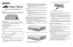
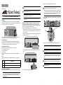
*613-000750 Rev B*
5.
613-000750 Rev. B
Warning: Do not work on equipment or cables during periods of lightning activity.
E2
Warning: As a safety precaution, install a circuit breaker with a minimum value of
15 Amps between the equipment and the DC power source.
Caution: Air vents must not be blocked and must have free access to room
ambient air for cooling.
E6
Always connect the wires to the LAN equipment first before you connect the wires
to the circuit breaker. Do not work with HOT feeds to avoid the danger of physical
injury from electrical shock. Always be sure that the circuit breaker is in the OFF
E9
position before connecting the wires to the breaker.
Warning: Operating Temperature. This product is designed for a maximum
ambient temperature of 40 degrees C.
E7
AT-PWR9 DC Power Supply Installation Guide
6.
All Countries: Install product in accordance with local and National Electrical
Codes.
E8
Overview
The AT-PWR9 Power Supply, as shown below, is a DC power supply for the AT-MR12
Media Conversion Rack-Mount Chassis. The power supply is shipped preinstalled in slot
A in the rear of the DC version of the AT-MCR12 chassis.
Secure the power supply by tightening the captive screws.
Identify the negative, frame ground, and positive terminals on the terminal block,
as shown below.
Installing an AT-PWR9 Power Supply as an Auxiliary Power Supply
You can install an AT-PWR9 Power Supply as an auxiliary power supply when the
AT-MCR12 chassis is operating and installed in a rack. To replace a power supply that has
failed, refer to “Hot Swapping an AT-PWR9 Power Supply.”
Frame Ground
To install an AT-PWR9 Power Supply, perform the following procedure:
1.
2.
Unpack all the items from the shipping container and store the packaging material in
a safe place. You must use the original shipping package if you need to return the
unit to Allied Telesis.
Positive
Negative
Remove the two screws that secure the blank faceplate covering the auxiliary power
supply slot, as shown below.
This guide describes how to install the AT-PWR9 Power Supply as an auxiliary power
supply for the chassis, and how to hot swap a power supply if one fails.
Related Documents
For details on the features and functions of the AT-MCR12 Media Conversion RackMount Chassis, refer to the following document on our web site, www.alliedtelesis.com:
7.
Before you strip and attach the wires, review the following safety precautions.
AT-MCR12 Media Conversion Rack-Mount Chassis Installation Guide
This system works with positive grounded or negative grounded DC systems.
E13
Verifying Package Contents
Make sure that the correct components are included in your package:
One AT-PWR9 Power Supply
This installation guide
Warranty card
3.
Turn the AT-PWR9 Power Supply upside down and slide it into the slot, as shown
below.
Warning: For centralized DC power connection, install only in a restricted access
E23
area.
If any item is missing or damaged, contact your Allied Telesis sales representative for
assistance.
A tray cable is required to connect the power source if the unit is powered by
centralized DC power. The tray cable must be UL listed Type TC tray cable and
rated at 600 V and 90 degrees C, with three conductors, minimum 14 AWG.
E24
LED
The AT-PWR9 Power Supply has one POWER LED as described in the following table.
Color
Warning: Circuit breaker is used as a disconnection device. To de-energize
equipment, shut down the circuit breaker and then disconnect the input wire.
E38
Description
Green
The power supply is operating normally.
Off
The power supply is off or has failed.
Warning: The DC input shall be from a secondary source isolated from the mains
by reinforced insulation.
Reviewing Safety Precautions
4.
Before you install the AT-PWR9 Power Supply, review the following safety precautions.
Press the power supply firmly into the backplane.
Note
The
indicates that a translation of the safety statement is available in a PDF
document titled Translated Safety Statements on the Allied Telesis website at
www.alliedtelesis.com.
1
2
3
8.
With a 14-gauge wire-stripping tool, strip the three wires in the tray cable coming from
the DC input power source to 8 millimeters ± 1 millimeters (0.31 inches ± 0.039
inches), as shown below.
8mm ±1mm
(0.31in. ±0.039in.)
Warranty Registration
Note
Allied Telesis hardware products are covered under limited warranties. Some products
have a longer warranty coverage than others.
Hot swapping requires that the main and auxiliary power supplies be connected to
separate DC circuits.
1.
This AT-PWR9 power supply has a limited warranty of 5 years.
Power off the appropriate DC circuit to the failed power supply.
All Allied Telesis warranties are subject to the terms and conditions set out on the Allied
Telesis website at www.alliedtelesis.com/warranty.
Warning: When installing this equipment, always ensure that the frame ground
E11
connection is installed first and disconnected last.
Physical Characteristics
Dimensions (H x W x L)
Warning: Do not strip more than the recommended amount of wire. Stripping
more than the recommended amount can create a safety hazard by leaving
exposed wire on the terminal block after installation.
E10
9.
Specifications
Connect the frame ground wire to the terminal marked with the ground symbol by
inserting the wire into the terminal block and tightening the connection with a flathead
screwdriver, as shown below. .
2.
Remove the positive and negative feed wires from the terminal block by loosening
the screws to the wire connections with a flathead screwdriver.
3.
Remove the frame ground wire from the terminal block by loosening the screw to the
wire connection with a flathead screwdriver.
4.
Loosen the captive screws on the failed power supply and slide it out of the chassis.
5.
Slide a new power supply into the slot.
6.
Refer to “Installing an AT-PWR9 Power Supply as an Auxiliary Power Supply” for
information about installing and wiring the replacement power supply.
Weight
.75 kg (1.65 lbs)
Operating Temperature
0° C to 40° C (32° F to 104° F)
Storage Temperature
-25° C to 70° C (-13° F to 158° F)
Operating Relative Humidity
5% to 90% RH (non-condensing)
Storage Relative Humidity
5% to 95% RH (non-condensing)
Power Requirements
Testing and Troubleshooting the Installation
Input Supply Voltage
Follow the guidelines in this section for testing and troubleshooting the installation in the
event that a problem occurs.
Maximum Inrush Current
10 A maximum
Maximum Current
4 A at 48 V DC
1.
Agency Certifications
2.
Warning: When installing this equipment, always ensure that the frame ground
E11
connection is installed first and disconnected last.
225 mm x 61 mm x 120 mm
(8.9 in x 2.4 in x 4.7 in)
Verify that the Power, PWR A and PWR B LEDs are green. If one of the LEDs is
OFF, do the following:
Check to be sure that the power supply is securely connected to the power outlet.
Check to be sure that the power supply is securely seated in the chassis.
Check to be sure that the wires are connected to the correct terminals.
Check to be sure that the DC power circuit is powered ON.
Check to be sure that the fans for both power supplies are operating. If a fan is not
operating, it is likely that the power supply has failed.
If you still have problems after testing and troubleshooting the installation, contact Allied
Telesis Technical Support at www.alliedtelesis.com for assistance.
36 to 72 V DC
Electrical Safety
UL60950-1 (cULus), EN60950-1 (TUV),
CSA 950
Immunity
EN50082-1
Emission
EN55022-1 Class A
Electrical, Safety, and Emissions Statements
This product meets the following standards.
10. Connect the positive feed wire to the terminal block marked + (positive).
U.S. Federal Communications Commission
11. Connect the negative feed wire to the terminal block marked - (negative).
Radiated Energy
Note: This equipment has been tested and found to comply with the limits for a Class A digital device
pursuant to Part 15 of FCC Rules. These limits are designed to provide reasonable protection
against harmful interference when the equipment is operated in a commercial environment. This
equipment generates, uses, and can radiate radio frequency energy and, if not installed and used
in accordance with this instruction manual, may cause harmful interference to radio
communications. Operation of this equipment in a residential area is likely to cause harmful
interference in which case the user will be required to correct the interference at his own expense.
Note: Modifications or changes not expressly approved of by the manufacturer or the FCC, can void
your right to operate this equipment.
Warning: Check to see if there are any exposed copper strands coming from the
installed wire. When this installation is done correctly there should be no exposed
copper wire strands extending from the terminal block. Any exposed wiring can
E12
conduct harmful levels of electricity to persons touching the wires.
12. Secure the tray cable near the rack framework using multiple cable ties (not
provided) to minimize the chance of the connections being disturbed by casual
contact with the wiring. Allied Telesis recommends that you use at least four cable
ties 10 centimeters (4 inches) apart with the first one located within 15 centimeters (6
inches) of the terminal block.
Industry Canada
This Class A digital apparatus meets all requirements of the Canadian Interference-Causing
Equipment Regulations.
Cet appareil numérique de la classe A respecte toutes les exigences du Règlement sur le matériel
brouilleur du Canada.
13. Ensure that the circuit breaker is in the Off position.
14. Connect the DC wires to the circuit breaker.
15. Power on the circuit breaker.
16. Verify that the Power LED is green. If it is not, refer to “Testing and Troubleshooting
the Installation.”
Hot Swapping an AT-PWR9 Power Supply
Copyright © 2007 Allied Telesis, Inc. All rights reserved. No part of this publication may
be reproduced without prior written permission from Allied Telesis, Inc.
This section describes how to replace a failed AT-PWR9 Power Supply in an AT-MCR12
chassis.
4
5
6