1
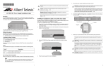
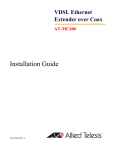
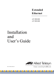
6.
*613-000743 Rev B*
Plug the power cord into the power connector on the chassis, as shown below.
Warning: To prevent electric shock, do not remove the cover. No userserviceable parts inside. This unit contains hazardous voltages and should only
be opened by a trained and qualified technician. To avoid the possibility of electric
shock, disconnect electric power to the product before connecting or
E1
disconnecting the LAN cables.
613-000743 Rev. B
PO WE R SU
Warning: Do not work on equipment or cables during periods of lightning activity.
E2
AT-PWR4 AC Power Supply Installation Guide
1225
Caution: Air vents must not be blocked and must have free access to room
ambient air for cooling.
E6
Overview
The AT-PWR4 Power Supply, as shown below, is an AC power supply for the AT-MCR12
Media Conversion Rack-Mount Chassis. The power supply is shipped preinstalled in slot
A in the rear of the AC version of the AT-MCR12 chassis.
7.
Warning: Operating Temperature. This product is designed for a maximum
ambient temperature of 40 degrees C.
E7
Plug the other end of the power cord into a wall outlet .
Warning: Power cord is used as a disconnection device. To de-energize
E3
equipment, disconnect the power cord.
All Countries: Install product in accordance with local and National Electrical
Codes.
E8
Warning: Class I Equipment. This equipment must be earthed. The power plug
must be connected to a properly wired earth ground socket outlet. An improperly
wired socket outlet could place hazardnous voltages on accessible metal parts.
E4
Installing an AT-PWR4 Power Supply as an Auxiliary Power Supply
You can install an AT-PWR4 Power Supply as an auxiliary power supply when the
AT-MCR12 chassis is operating and installed in a rack. To replace a power supply that has
failed, refer to “Hot Swapping an AT-PWR4 Power Supply.”
CentreCOM PWR4
PPLY B
Pluggable Equipment. The socket outlet shall be installed near the equipment and
shall be easily acceptable.
E5
To install an AT-PWR4 Power Supply, perform the following procedure:
1284
Related Documents
For details on the features and functions of the AT-MCR12 Media Converstion RackMount Chassis, refer to the following documents on our web site, www.alliedtelesis.com:
1.
Unpack all the items from the shipping container and store the packaging material in
a safe place. You must use the original shipping package if you need to return the
unit to Allied Telesis.
2.
Remove the two screws that secure the blank faceplate covering the auxiliary power
supply slot, as shown below.
AT-MCR12 Media Conversion Rack-Mount Chassis Installation Guide
Warning: This unit might have more than one power source. To reduce the risk of
electric shock, disconnect all power sources before servicing the unit.
E30
Hot Swapping an AT-PWR4 Power Supply
Verifying Package Contents
This section describes how to replace a failed AT-PWR4 Power Supply in an AT-MCR12
chassis.
Make sure that the correct components are included in your package:
1.
One AT-PWR4 Power Supply
This installation guide
Warranty card
POW ER SUPP
LY A
POW ER SUPP
POWER
Cen t r e COM P WR4
If any item is missing or damaged, contact your Allied Telesis sales representative for
assistance.
LY B
LED
Color
Description
Green
The power supply is operating normally.
Off
The power supply is off or has failed.
Remove the other end of the power cord from the failed power supply.
3.
Loosen the captive screws on the power supply and slide it out of the chassis.
4.
Slide a new power supply into the slot.
5.
Refer to “Installing an AT-PWR4 Power Supply as an Auxiliary Power Supply” for
information about installing the replacement power supply.
Follow the guidelines in this section for testing and troubleshooting the installation in the
event a problem occurs.
Turn the AT-PWR4 Power Supply upside down and slide it into the slot, as shown
below.
Reviewing Safety Precautions
2.
Testing and Troubleshooting the Installation
1223
The AT-PWR4 Power Supply has one POWER LED as described in the following table.
3.
1.
CentreCOM PWR4
POWER
POW ER SUPP
LY A
Before you install the AT-PWR4 Power Supply, review the following safety precautions.
POW ER SUP
2.
PLY B
POWER
The
indicates that a translation of the safety statement is available in a PDF
document titled Translated Safety Statements on the Allied Telesis website at
www.alliedtelesis.com.
1
CentreCOM PWR4
Note
4.
Press the power supply firmly into the backplane.
5.
Secure the power supply by tightening the captive screws.
Remove the power cord from the wall outlet.
Verify that the Power, PWR A and PWR B LEDs are green. If one of the LEDs is
OFF, do the following:
Check to be sure that the power supply is securely connected to the power outlet.
Check to be sure that the power supply is securely seated in the chassis.
Check to be sure that the wires are connected to the correct terminals.
Check to be sure that the DC power circuit is powered ON.
Check to be sure that the fans for both power supplies are operating. If a fan is not
operating, it is likely that the power supply has failed.
If you still have problems after testing and troubleshooting the installation, contact Allied
Telesis Technical Support at www.alliedtelesis.com for assistance.
1224
2
3
Warranty Registration
Allied Telesis hardware products are covered under limited warranties. Some products
have a longer warranty coverage than others.
This AT-PWR9 power supply has a limited warranty of 5 years.
All Allied Telesis warranties are subject to the terms and conditions set out on the Allied
Telesis website at www.alliedtelesis.com/warranty.
Specifications
Physical Characteristics
Dimensions (H x W x L)
225 mm x 61 mm x 120 mm
(8.9 in x 2.4 in x 4.7 in)
Weight
0.77 kg (1.7 lbs)
Operating Temperature
0° C to 40° C (32° F to 104° F)
Storage Temperature
-25° C to 70° C (-13° F to 158° F)
Operating Relative Humidity
5% to 90% RH (non-condensing)
Storage Relative Humidity
5% to 95% RH (non-condensing)
Power Requirements
Power Rating
100-120 VAC, 50/60 HZ, 3.0 A
220-240 VAC, 50/60 HZ, 1.5 A
Agency Certifications
Electrical Safety
UL60950-1 (cULus), EN60950-1 (TUV),
CSA 950
Immunity
EN50082-1
Emmission
EN55022-1 Class A
Electrical, Safety, and Emissions Statements
This product meets the following standards.
U.S. Federal Communications Commission
Radiated Energy
Note: This equipment has been tested and found to comply with the limits for a Class A digital device
pursuant to Part 15 of FCC Rules. These limits are designed to provide reasonable protection
against harmful interference when the equipment is operated in a commercial environment. This
equipment generates, uses, and can radiate radio frequency energy and, if not installed and used
in accordance with this instruction manual, may cause harmful interference to radio
communications. Operation of this equipment in a residential area is likely to cause harmful
interference in which case the user will be required to correct the interference at his own expense.
Note: Modifications or changes not expressly approved of by the manufacturer or the FCC, can void
your right to operate this equipment.
Industry Canada
This Class A digital apparatus meets all requirements of the Canadian Interference-Causing
Equipment Regulations.
Cet appareil numérique de la classe A respecte toutes les exigences du Règlement sur le matériel
brouilleur du Canada.
Copyright © 2007 Allied Telesis, Inc. All rights reserved. No part of this publication may
be reproduced without prior written permission from Allied Telesis, Inc.
4
5
6