1
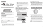
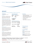
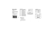
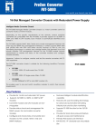
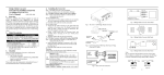
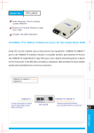
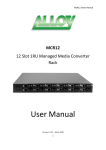
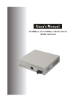
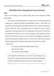
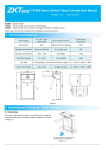
10/100Base-TX to 100Base-FX
Fast Ethernet Converter Module
User's Manual
(620−1231−000)
MFCR100SC.05
MFCR100SC.20
1. Overview
The MFCR100 Series is designed to convert
between 10/100Base-TX and 100Base-FX
Fibre Ethernet. The converter module is
designed to be installed into the MCR12
Managed Media Converter Chassis.
2. Checklist
Before you start installing the Converter, verify
that the package contains the following:
⎯
The TP-Fibre Converter Module
⎯
This User's Manual
Please notify your sales representative
immediately if any of the aforementioned items
is missing or damaged.
MFCR100SC.40
MFCR100SC.60
MFCR100BS5.20
MFCR100BS3.20
MFCR100BS5.40
MFCR100BS3.40
BiDi SC
MFCR100BS5.60
SC
MFCR100BS3.60
10/100Base-TX to 100Base-FX
Converter Module, SC Single-Mode
5Km
10/100Base-TX to 100Base-FX
Converter Module, SC Single-Mode
20Km
10/100Base-TX to 100Base-FX
Converter Module, SC Single-Mode
40Km
10/100Base-TX to 100Base-FX
Converter Module, SC Single-Mode
60Km
10/100Base-TX to 100Base-FX
Converter Module, Bidi SC SingleMode 20Km, 1550nm
10/100Base-TX to 100Base-FX
Converter Module, Bidi SC SingleMode 20Km, 1310nm
10/100Base-TX to 100Base-FX
Converter Module, Bidi SC SingleMode 40Km, 1550nm
10/100Base-TX to 100Base-FX
Converter Module, Bidi SC SingleMode 40Km, 1310nm
10/100Base-TX to 100Base-FX
Converter Module, Bidi SC SingleMode 60Km, 1550nm
10/100Base-TX to 100Base-FX
Converter Module, Bidi SC SingleMode 60Km, 1310nm
Fig. 1 Converter Module Front Panel
3. Model Description
Model
MFCR100SC
MFCR100ST
Description
10/100Base-TX to 100Base-FX
Converter Module, SC Multi-Mode
10/100Base-TX to 100Base-FX
Converter Module, ST Multi-Mode
1
4. DIP Switch Setting
Converter AUTO, FORCE selectable: Bit 1 of S1
TP Port
a. AUTO: 10/100 Nway (default)
100TP
b. FORCE: 100 FDX
2
Converter LFP function selectable: Bit 2 of S1
LFP
a. LFP function: OFF (default)
Function b. LFP function: ON
TP-FORCE
LFP
ON
Default: 100FDX
Fibre Attach the fibre cable. The Tx, Rx
Port fibre cable must be paired at both
ends
TP
Port
Attach TP cable to TP port
Mode: 10/100Mbps with NWay
S1
1
2
TP-AUTO
LFP
OFF
Fig. 2 S1—Bit 1, 2 Configuration and Setting
S1-1 TP port mode: AUTO (default) or FORCE
S1-2 LFP function: LFP OFF (default) or ON
5. Installing the Converter
Note: Converter modules are hot-swappable.
⇒
Wear a grounding device for
electrostatic discharge.
⇒
Unscrew and remove the
cover plate from the converter chassis.
⇒
Verify the converter module is the right
model and conforms to the chassis slot.
⇒ Slide the module along the two guides in
the slot and fasten the thumb knob, be
sure the converter module is properly
seated on the slot socket/connector.
⇒ Install the media cable for network
connection.
⇒ Repeat the above steps, as needed, for
each module to be installed into slot(s).
3
4
6. Link Fault Pass Through
Link Fault Pass Through allows the link fault of
one device to be passed through to the connecting
device. If the copper or fibre port of one converter
fails then both the copper and fibre ports on the
connecting media converter will also fail. This can
be used as a means of determining network faults.
10/100Mbps NWay
TP Network
TS-1000
--------------------------------10/100 TP to 100 FX
Fiber
--------------------------------TX: 1310 nm
RX: 1550 nm
10/100Mbps NWay
TP Network
Single Fiber
TS-1000
--------------------------------10/100 TP to 100 FX
Fiber
--------------------------------TX: 1310 nm
RX: 1550 nm
62.5/125μm, 50/125μm multi-mode
• LED Indicators:
PWR,
FX LINK/ACT,
TP LINK/ACT, SPEED
• Data Transfer Rate
Speed
Forwarding Rate
100Mbps
148,800 PPS
10Mbps
14,880 PPS
7. LED Description
LED
Color
Function
POWER
Green
Lit when +5V power is coming up
FX LINK/ACT
Green
Lit when fibre connection is good
Blinks when any traffic is present
TP LINK/ACT
Green
Lit when TP connection is good
Blinks when any traffic is present
TP SPEED
Green
Lit when 100Base-TX is active
OFF: when 10Base-T is active
TS-1000
TX
100FX
Fibre
RX
Network
Fig. 4 Fast Ethernet Converter Network Connection 2
• TP
8. Cable Connection Parameter
yTP Cable Limitations: Cat. 5 and above up to
100m
yFibre Cable Limitations:
- Single-mode fibre 9/125μm and up to 60Km
- Multi-mode fibre 62.5/125μm, 50/125μm and up to 2Km
•
•
•
•
: 10/100FDX/HDX with NWay
auto-negotiation
Fibre : 100FDX/HDX
Power Requirement: 0.46A@+3.3VDC
Ambient Temperature : 0° to 40°C
Humidity : 5% to 90%
PCB Dimensions : 86(L) * 60(W) mm
TX
RX
TP-to-100FX
Converter
100Mbps NWay
TP Network
Fig. 3 Fast Ethernet Converter Network Connection 1
1
10. TP-Fiber Technical Specifications
• Standards: IEEE802.3u 10/100Base-TX,
100Base-FX
• Management: Support remote access,
remote monitor and loopback test
functions through TS-1000
specification
• UTP Cable: Cat. 5 cable and above up to
100m
• Fibre Cable:
9/125μm single-mode
2
11. TS-1000
TS-1000 function performs the loopback test
between central and remote converter, the
indication frames would inform its status when
central or remote side has any change.
Note:
The TS-1000 function will be performed
entirely only when the central and remote TS1000 converters are supplied by the same
vender.
3
4