1
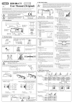
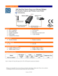
WWW.PHIHONG.COM 19.6W Power over Ethernet Adapter DC Input Single Port Injector Features Detection and Classification per IEEE802.3af Diagnostic LEDs Non-Vented Case DC Input Voltage 18-72VDC 1 Year Warranty Applications IP Telephones Wireless Network Access Points Blue Tooth Access Point UNH IOL Tested Full Protection OCP, OVP Gigabit Compatible Lowest cost DC Input Power Injector Security Cameras IP Print Servers Height: 36mm (1.42in) Weight: 0.2Kg (0.44lb.) Safety Approvals CE± Mechanical Characteristics Length: 140mm (5.51in) Width: 65mm (2.55in) Output Specifications Model DC Output Voltage POE20D-1AF 56V Load Regulation Min. Max. 0A 0.35A Line Load 54-57Vdc under all conditions Phihong is not responsible for any error, and reserves the right to make changes without notice. Please visit our website at www.phihong.com for the most up-to-date specifications and contact information. POE20D – 1AF Characteristics INPUT: DC Input Voltage Range 18 to 72VDC DC Input Current 1.5A for 18V DC and maximum load OUTPUT: Total Output Power 19.6W at 56VDC DC Offset No data degradation with DC imbalance 18mA 80% at maximum load (>36 to 72VDC) 75% at maximum load(18 to <36VDC) Primary to Secondary: 2121VDC for 1 minute, 10mA Primary to Field Ground: 2121VDC for 1 minute, 10mA Output to Field Ground: 2121VDC for 1 minute, 10mA Immunity ESD: RS: EFT: Surge: CS: Voltage Dips Harmonic: EN61000-4-2. Level 3 EN61000-4-3. Level 3 EN61000-4-4. Level 2 EN61000-4-5. Level 3 EN61000-4-6. Level 3 EN61000-4-11 EN61000-3-2 Primary to Secondary: >10M OHM 500VDC Primary to Field Ground: >10M OHM 500VDC FEATURE: Ripple and Regulation 100mV maximum at ambient 25°C Transient O/P Voltage Protection 60V maximum at switch on and off ENVIRONMENTAL: Temperature -20 to +50°C -25 to +85°C Humidity Operation Isolation Test Insulation Resistance Efficiency Operation Non-operation WWW.PHIHONG.COM 5 to 90% EMC FCC Part 15 Class B EN55022 Class B Dimension Diagram Unit: mm (inch) Over Voltage/Current, Short Circuit Protection Outputs equipped with short circuit protection and overload protection as per 802.3af specification The output can be shorted permanently without damage Indicators Green LED 1: Input power “ON” Red LED: Fault detected Green LED 2: Valid IEEE802.3af load detected and connected Input Connector – Anytek OQ0355510000G Mate – Anytek TJ0350520000G or TJ035152000G Anytek is part of Giga-Way Technology Corp Output Connection +pins 3, 6 -pins 1 ,2 Warranty 1 Year Gigabit Power Injector Block Diagram Description of LED Functions for Gigabit Power Injector Power-up Sequence: Upon power-up, all 3 LEDs will light for 2 seconds, as part of the self-test for the internal microprocessor software. After the end of the 2 seconds, the "ON" LED will illuminate green, signifying that the DC output voltage is available for powering a compliant load (to the 802.3af PoE standards). Detection Sequence: Once a compliant load is attached to the output RJ45 connector, the green "CONNECT" LED will illuminate. Should the load be non-compliant then the LEDs will blink a code signifying the cause for nondetection. Detection Failure Codes: 1. Incorrect resistive signature – The green “CONNECT” and red “FAULT” LEDs will blink 3 times. 2. Incorrect capacitive signature – The green “ON” LED will blink 3 times. 3. Incorrect Voffset – The green “CONNECT” and green “ON” LEDs will blink 3 times. 4. Unstable current measurement – The green “ON” LED will blink 3 times 5. Low voltage sensed during detection (overload) – The red “FAULT” LED will blink 3 times After the LEDs blink 3 times the Power Injector will continue to try to detect a valid load. Therefore, until the correct load is applied, the LEDs will continue to blink. If there is an open circuit connected to the output RJ45 then the LEDs will not blink but the Power Injector will continue to try to detect a valid load. Fault Sequence: Should there be a fault such as an overload or short circuit then the red "FAULT" LED will illuminate. The red “FAULT” LED will illuminate for 2 seconds and then go off as the power supply tries to redetect a valid load. If there is a problem in detecting, the LED will indicate what is wrong with the load as per the codes in the section above.