1
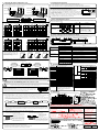
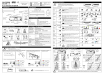
HR100-CT
User Manual (Original)
EN
4. Dip Switch Settings
Setting Mode: Before changing other dip switch settings, the setting mode dip switch Y -7 must be
turned ON. When the “setting mode” dip switch is turn ON the relay will activate causing the door to
remain open. Once all other dip switch settings are configured, dip switch Y -7 should be turned OFF.
When dip switch setting are changed an Orange LED blinks rapidly until the change takes effect,
during this time period stay out of the detection area of the sensor.
CAUTION
!
We would like to extend our thanks to you for purchasing this product. Before using this product, please read the
following instructions carefully.
Please retain this manual for reference in case it needs to be referred to during the lifetime of this product.
Y Direction Detection
Door hold open time and building energy losses
can be reduced by turning ON “Direction
Detection” recognition. Pedestrians moving
away from the sensor will not be detected.
NOTE: For pedestrian
safety purposes when
“Doorway L e a r n ” is
set to ON the 1st and
2nd row of detection
will detect pedestrian
regardless of direction.
OFF
“Maximum Safety” due to the ability of HR100-CT to look back into the door close area without detecting door motion.
Minimum Building Energy losses due to pedestrian “Direction Detection” technology built into the HR100-CT sensor.
EC type-examination certificate registration No: 44 205 11 391027-001 valid from 2011.
ON
1
WARNING
COMPLIED STANDARDS
This symbol indicates a dangerous situation. If the
user ignores this symbol then injury or damage to
equipment can result.
DIN18650-1:2005
EN 12978:2003
Dip Switch X
Dip Switch Y
Y Output A setting (Door Safety)
ON
!
CAUTION
ON
!
This symbol indicates an extremely dangerous
situation. If the user ignores this symbol then
serious injury or death can result.
1 2 3 4 5 6 7 8
1 2 3 4 5 6 7
Output logic can be set to N.O. or N.C.
In the N.O. setting the opto-coupler is open when
there is no detection and is driven when there is
N.C.
detection.
In the N.C. setting, the opto-coupler is driven
2 when there is no detection and open when there
is detection.
When the sensor power is OFF the opto-coupler defaults
to the “Open” state.
Refer to [5.Timing Chart of events].
N.O.
1. Part Identification
X Inner 3 Rows Presence Timer
Accessories
The sensor will detect a stationary object for
the preset presence timer setting. If the object
does not move during this preset time period,
the door will close.
2S
30S
Cover
Potentiometer
Dip Switch Y
(Sensitivity Volume)
Connector
Dip Switch X
Depth Adjustment
Lever Arm
(Outer 2 Rows)
Mounting Template
60S
Set the timer to 60sec. or more to
comply with DIN18650.
Y Output B setting (Door Activation)
N.C.
Depth Adjustment
Lever Arm
(Inner 3 Rows)
X Quantity of Rows
Cable
Indicator LED
(Red & Green)
Area Mask
Area Mask
(Outer 2 Rows)
(Inner 3 Rows)
Detection Window
R4
Base
Mounting Screws
(2 pcs.)
3
The number of rows of detection can be set to
5, 4, 3, 2 depending on detection area
requirements.
R5
When the sensor power is OFF the mechanical relay
defaults to the “Open” state.
Refer to [5.Timing Chart of events].
R3
Y Test Input setting from Door Controller
R2
2. Mounting Caution
Mount within 50 mm of the bottom
Ensure there are no moving objects
of the door engine cover. If the unit is in detection zone.
mounted higher, it cannot learn the
door close area.
3.0m
(9.84ft)
R5R4 R3 R2 R1
Low
X Frequency
4
Refer to [5.Timing Chart of events].
When more than two sensors are installed in
close proximity to each other select different
frequency settings for each sensor to prevent
interference.
A
B
Without TEST
High
C
Max 50mm
Low
D
Ensure no condensation gets onto
If possible ensure no accumulation
Ensure rain & snow do not fall on
of snow or water on the floor.
the sensor. (Use a weather cover if the sensor.
necessary)
Ensure the minimum of reflected
sunlight from the floor.
5 6
A
B
To maximize the effectiveness of doorway detection, install
the HR100-CT outside and inside as shown below.
A
B
A
Moving Door Leaf
Moving Door Leaf
B
Side View
Plan View
X Doorway Learn
WARNING
0v
0v
In some instances the reflection from the floor can
be very low, the HR100-CT can sometimes judge
this as an error state with the dip switch set to
Low
“Normal” (OFF). This low reflection state will be
indicated by an alternate slow flashing Red/Green
Ref.
LED.
5 To ignore this low reflection error state, set this dip
switch to “Low Reflection”(ON).
Refer to [9. Sensor Self Diagnostics Error].
NOTE: Set to “Low Reflection” during maintenance work on the
door controller.
Refer to [10. Sensor Settings for Door Maintenance Work].
Normal
ON
Doorway Learn ON
Doorway Learn when turned ON allows the 1st row of
detection to be focused back inside the door close area
without the sensor detecting door movement. When
Doorway Learn is OFF ensure that the first row of detection
is focused directly in front but not inside the moving door
leaves.
Set to “Normal” to comply with DIN18650.
NOTE: When Doorway Learn is turned ON, the inner row
of detection that is monitoring the closing door is only at
maximum sensitivity when the outer rows of detection of the
sensor are activated.
Y Monitor Mode
Snow
6
OFF
Y Setting Mode
8
When “Doorway Sensitivity” is set to “OFF” once the door
closes the sensitivity level on the inner most row of
detection which is looking back into the door close zone
goes to zero thus preventing unwanted or unauthorized door
activations from the side of the door where the sensor is not
installed.
Attach the mounting template so that its bottom edge is flush with the bottom edge
of the door engine cover and drill mounting (3.5mm
Snow Mode should only be used in
environments where heavy snowfall or other
extreme conditions exist.
Normal
Only selectable when “Doorway Learn”
above is turned “ON”
Normal
Drilling may cause Electric shock!
When drilling, pay attention to wires inside the door engine cover.
Without TEST
Y Reflection Diagnostics
Doorway Learn OFF
OFF
X Doorway Sensitivity
3. Mounting and Wiring Information
With TEST
Set to “Low” to comply with DIN18650.
7
Use a different frequency settings for sensors in
close proximity to each other as illustrated below.
TEST input is the input signal from the door controller.
The TEST input signal from the door controller that the
sensor can recognize can be set to “High” or “Low”.
When connected to a door controller without a TEST
input set to “High”. when connected to a door
controller with a TEST input set to “Low”
High
3 4
Mount lower than 3.0m (9.84ft).
!
Output logic can be set to N.O. or N.C.
In N.O. setting the mechanical relay is open
when there is no detection and is closed when
there is detection.
In the N.C. setting, the m ech an ic al rel ay is
closed when there is no detection and open
when there is detection.
N.O.
1 2
Installation Instruction
OFF
ON
7
Turn ON to configure all other dip switch
settings. When ON the sensor will output a
detection signal and the LED will be Dark
Red.
NOTE: Refer to the caution in [4.Dip
Switch Settings]
Default Settings
50mm
5. Timing Chart of events
Remove the sensor cover.
If you need to remove the sensor body
Attach the sensor with the
from the base then lift the sensor body from mounting screws provided
the base and tilt it forward to remove as
illustrated. 1
Output A Row 1, 2
Dip Switch Y
Spread and pull cover off
Test
54 3 2 1
POWER OFF
Output A setting
1
/
54 3 2 1
NONDETECTION
54 3 2 1
Yellow
Blue
Yellow
Blue
Yellow
Blue
Yellow
Blue
Yellow
Blue
N.C.
Yellow
Blue
Yellow
Blue
Yellow
Blue
Yellow
Blue
Yellow
Blue
Yellow
Blue
2
Connect “Test Input” wires to the door
WITH a test input controller to comply with DIN18650.
TEST RESPONSE
T1
Test Input
Sensor’s
Cable
Cable
Black
AC/DC
12 to 24 [V]
±10%
White
N.O.
Green
COM
Yellow(+)
Collector
Blue(-)
Gray(+)
Brown(-)
Dip Switch Y
Test Input setting
Power
Non Pole
Red
Sensor’s
Cable
Cable
R2,3,4,5
Output
Emitter
R1,2
Output
do not connect
do not connect
Black
AC/DC
12 to 24 [V]
±10%
White
N.O.
Green
COM
Yellow(+)
Collector
Blue(-)
Emitter
Test-P
Brown(-)
Test-N
House connectors in the
Set Dip Switch, Lever
space provided.
Arms and Potentiometer
settings as desired.
(See Section 4 and 5)
!
TEST
NON-TEST
TEST
TEST
NON-TEST
Test Input setting
Low
NON-TEST
4
Gray
Sensor
Brown
Test Input
T1 : 10±1 [mSec] App
T2 : 11±1 [mSec] App
Gray
Sensor
Brown
Supplying DC12 to 24V, make
current flow from Gray to Brown.
Output B Row 2, 3, 4, 5
4
Replace Cover.
CAUTION
High
DETECTION as
response to TEST
T2
Gray
R1,2
Output
Low
Test Input setting
4
Dip Switch Y
R2,3,4,5
Output
Gray(+)
Dip Switch Y
High
Power
Non Pole
54 3 2 1
NON-DETECTION
Yellow
Blue
Connect Wires to the door controller.
Red
54 3 2 1
DETECTION
N.O.
2
WITHOUT a test input
Input
Dip Switch Y
Depth Adjustment
Lever Arm
Be careful not to inadvertantly
move the Depth Adjustment Lever
Arms when replacing the cover.
54 3 2 1
54 3 2 1
NONDETECTION
54 3 2 1
Output B setting
POWER OFF
N.O.
Green
White
Green
White
Green
White
N.C.
Green
White
Green
White
Green
White
3
DETECTION
Break the current
flow on test state.
Brown
Sensor
6. Adjusting the Infrared Detection Area
8. Verification of Operation
6-1 Adjusting the outer 2 rows and inner 3 rows of Detection:
The detection distance from the door for the inner 3 rows and outer 2 rows of detection can be adjusted seperately using the lever arms
on the left and right hand side of the sensor as illustrated below.
Without Base
Inner 3 Rows
Outer 2 Rows
ROW1
ROW2
ROW3
ROW4
ROW5
ROW1
ROW2
ROW3
ROW4
ROW5
Inner 3 Rows
Outer 2 Rows
Inner 3 rows can be adjusted so that the
innermost row of detection can look
back into the door close area as long as
“Doorway Learn” is set to ON
Area Adjustment Lever Arms
for Inner 3 Rows
[m]
1.0
0.5
[m]
1.0
0
[0 degree] setting
Inside Door
Close Area
0.5
3.0
0
2.0
1.0
[m]
2.0
0
1.0
[m]
0
[0 degree] setting
[+10 degree] setting
1.0
1.0
Sensor self diagnostics failure is indicated by a Green/Red LED flashing. The speed of the LED flash indicates the
type of error that has occurred.
LED
Cause
Solution
With Base
Area Adjusting Lever Arms for Outer 2 Rows
[-8 degree] setting
(1) When the sensor does not detect objects in the detection area the sensor
sensitivity can be increased by turning the potentiometer clockwise
L
H
(2) When the sensor detects even though there is nothing in the detection area
then the sensor sensitivity can be decreased by turning the potentiometer in
the anti-clockwise direction
NOTE: To achieve detection of the CA test body in accordance with DIN18650 please set the sensor sensitivity to
the highest setting. If the “doorway learn” is turned ON and the 1st row of detection is monitoring the doorway
ensure that the 2nd row of detection can detect the CA body.
9. Sensor Self Diagnostics Error
Area Adjustment Lever Arms
for Outer 2 Rows
Area Adjusting Lever Arms for Inner 3 Rows
Green
Fast Flashing
1.0
Green
Slow Flashing
Door
2.0
2.2
Door
2.0
2.2
2.0
2.2
2.0
2.2
3.0
3.0
3.0
3.0
0.5
0
[m]
1.0
[0 degree] setting
0.5
Area Adjusting Lever Arms for Outer 2 Rows
2.0
0
[-8 degree] setting
1.0
[m]
2.0
0
[+10 degree] setting
1.0
Low reflection
level
Red
Confirm that the sensitivity
potentiometer is set to maximum, and
then reactivate the sensor. If the error
continues, set Dip Switch Y -5 to
“Low Reflection” .
Refer to [4. Dip Switch Settings].
10. Sensor Settings for Door Maintenance Work
Dip Switch X
[m]
Dip Switch Y
0
ON
[m]
Please replace the sensor.
When carrying out door maintenance work with power applied to the sensor please set the dip switches as below.
NOTE: remember to return the dip switch settings to their original state once door maintenance work has been carried out.
Without Base
1.0
Internal error
Red
1.0
Area Adjusting Lever Arms for Inner 3 Rows
Sensitivity
How to adjust the sensitivity
[0 degree] setting
1 2 3 4 5 6 7 8
ON
With Base
1. After installation is completed, verify the infrared detection area.
2. If the doors do not move as expected, readjust the infrared detection area.
3. If the doors do not move as expected after the above procedure then adjust the sensitivity.
Low
Ref.
2S
1.0
Door
1.0
1.0
1.0
2.0
2.2
2.0
2.2
2.0
2.2
11. Trouble shooting
Door
2.0
2.2
Problems
Cause
Door does not operate.
3.0
3.0
3.0
3.0
6-2 Deleting rows of detection:
5 Rows ON
Using the “Quantity of Rows” dip
switch, detection rows 5,4 and 3 can
be turned ON or OFF [See Section
4.Dip Switch Setting]
4 Rows ON
3 Rows ON
2 Rows ON
Door operates
Intermittently.
Solution
Sensor Connector
Tighten connector or reconnect.
Power Supply
Apply proper voltage to the sensor. (AC/DC 12-24V)
Sensor is very dusty or covered with water
drops etc.
Clean the sensor. (Do not use thinner or alcohol.)
Detection sensitivity to low.
Increase sensitivity by turning clockwise.
Incorrect detection pattern setting.
Set the correct detection patterns to suit the installation environment.
detection row “ROW1” (“ROW2” when
doorway learning is turned ON) is focused too Adjust detection depth for Inner 3 rows away from the door.
close to the door.
Door opens & closes
Repeatedly.
(Sensor detects door.)
Remove
6-3 Detection Area Width Adjustment :
Door operates by itself.
Detection Area Width Settings for outer 2 rows and inner 3 rows of detection can be incrementally adjusted by turning
the Area Masks using a screw driver etc as illustrated below.
Area Mask
(Inner 3 Rows)
Width
2.0
1.0
Area Mask
(Outer 2 Rows)
0
1.0
2.0 [m] 2.0
Narrow
Wide
0
1.0
Wide Area
1.0
Narrow Area
Narrow
Wide
1.0
Outer 2 Rows are set too far from the door
Sensitivity too high.
Turn down the sensitivity.
Another sensor is installed close by.
Ensure different frequency setting for each sensor.
This may cause the door to remain open. Reduce the presence timer setting to ensure
shorter door hold open times.
12. Technical Data
Width
2.0
moving object from detection area.
Reduce the detection distance of the sensor using the area adjustment lever, the
detection area mask or the quantity of rows dip switch so as not to detect passing
people.
Model Name
HR100-CT Motion and Presence Sensor
Detection Method
Active Infrared Reflective Detection
Open collector 7.5 [mA] (Max) Resistor Load
Installation Height
3.0[m] (9.84 [ft]) Max
Depth Detection
Adjustment
Depth Adj. Lever
Outer 2 rows 10 [deg.]
Inner 3 rows 8 [deg.]
Dip SW.
Total Detection Rows 5,4,3 or 2
ROW
1,2
Output
Outer 2 Rows
Area Mask For Narrow or Wide
Inner 3 Rows
Area Mask For Single or Double Door
Noise Prevention
Dip SW.
Normal or Snow Mode
Cross Interference
Dip SW.
One of 4 frequencies
Width Detection
Adjustment
2.0
3.0
ROW
2,3,4,5
Output Holding Time 0.5 [seconds] App.
Response Time
7. Applying Power & Initializing if Doorway Learn is “ON”
!
CAUTION
If “Doorway Learn” is set to “ON” read the below instructions before applying power in order to understand the
procedure involved in getting the inner most row of detection to learn the door close zone.
7-1 Doorway Initialisation:
Presence Timer
1 [seconds]
Inner 3 Rows
Dip SW.
Dip SW.
OFF or ON
Doorway Sensitivity
Dip SW.
Normal or OFF
Direction Detection
Setting Mode
Dip SW.
Dip SW.
OFF or ON
OFF or ON
Power Supply
AC/DC 12 to 24 [V] ±10% 50/60Hz Red : Black
AC12V-2.1 [VA] (Max) , AC24V-2.1 [VA] (Max)
DC12V-110 [mA] (Max) , DC24V-60 [mA] (Max)
Green – Standby
Green blinking – Doorway Learning
Red – Detecting
Orange – Detection row “ROW1”(“ROW2” when doorway
learning is turned ON) is focused too close to the door.
Orange blinking – Dip switch setting are changed.
Green/Red blinks alternately – Internal Sensor Error
Dark Red – Setting Mode
Power Consumption
Door Close
Acquiring
Door Data
N.C. Normally Closed
Open on Detection
High Non-Test : Open
Test : DC12 to 24 V
Low Non-Test : DC12 to 24 V
Test : Open
-20 to +60 [Deg.C],(-4 to 140 Deg.F)
Operating humidity
Below 80%
IP Rate
Weight
IP54 (With Base)
2 , performance level D for presence detection according to
EN ISO 13849-1:2008
0.55 [lb.] (0.25 [kg])
Color
Black, Silver
Accessories
Cable , Mounting Screw 2pcs.,
Mounting Template, Installation Instruction
Notice: Specification may be changed without prior notice.
33.5 mm
(1.32")
66.5 mm
(2.62" )
Door Fully Closed: Learning
Procedure Complete
230mm(9.06")
Green Initializing LED blinks for about 37 seconds indicating that the doorway learning procedure is being carried out.
Once complete the Green LED turns off
(2) Doorway Learn Failure and Recovery: During the doorway learn process if a person enters the detection area the doorway learn
process may not be successfully carried out. In this case the HR100-CT sensor will carry out the doorway learn process over three
door activations by a person in order to build an accurate image of the door open and door close position. Again in this case all
other rows of detection will go to presence detection immediately with the second row of detection maintaining safety in front of
the door close zone.
7-3 How Presence Detection is Initiated after Sensor Power Up
10 seconds for presence
timer to function
4
Test
Input
setting 4
Open
N.O. Normally
Closed on Detection
75mm(2.95") = Standard Mounting Pitch
NOTE: During the doorway learn procedure, the doorway detection row (inner most row) can detect motion only while all other
rows can detect presence (While doorway learn is being carried out the second row of detection maintains presence detection and
protects pedestrians from dangerous door closures).
“Doorway Learn” dip switch set to OFF
Output 3
B
setting 3
13. Dimensions
(1) Doorway Learn Procedure: The below procedure is carried out each time power is turned ON. The sensor will automatically send
an output signal to the door controller triggering the door open/close cycle thus initiating the “doorway learn” process .
Acquiring Floor Data
Open on Detection
Operating Temperature
Category
First ensure that the “Doorway Learn” dip switch is set to “ON” and keep out of the detection area of the sensor
Door Open
N.C. Normally Drive
Green LED
7-2 Doorway Learn Procedure:
Power ON
Open
N.O. Normally
Drive on Detection
6 [mA] Max. @ 24 [VDC]
2,30,60 [seconds] or
Doorway Learn
LED Indication
Doorway initialization is the procedure that needs to be carried out so that the inner most row of
detection can “learn” door movement.
When doorway “learning” is being carried out the Green LED blinks. When the doorway “learn”
procedure has been successfully completed the Green LED stops blinking.
Outer 2 Rows
White : N.O.
Green : COM
Gray : Test-P
Brown : Test-N
Test Input
0.2 [seconds]
Output 2
A
setting 2
“Doorway Learn” dip switch set to ON
It takes 10 seconds after sensor
power up for presence detection to
be initiated on all rows of
detection.
If before 10 seconds have elapsed
someone walks into the detection
area it will take about 5 seconds
after the person leaves the
detection zone for presence
detection to be functional.
It will take the 1st row
of detection 37 seconds
to “learn” the door open
and close position.
During this time rows 2 to 5 go to a
st a t e of p res en c e d e t ec t i on 1 0
seconds after the sensor is powered
ON to ensure safety while the “door
learn” procedure is being carried out
70.4 mm(2.77")
!
The above illustrated detection areas represent the actual position of the infrared beams. The actual
detection area observed will vary depending on the sensor installation environment, object been
detected and sensor settings. Please ensure that the detection area is set to conform to DIN18650.
0.1
Yellow : Collector
Blue : Emitter
Opto coupler(NPN)
Voltage : 55 [VDC] Max. Current : 50 [mA] Max.
Dark Current : 100 [nA] Max. (Resistance load)
Form A Relay DC50 [V] 0.1[A] Resistor Load
Sensitivity Adjustment By Potentiometer
CAUTION
1 2 3 4 5 6 7
44mm
(1.73")
HR100-CT EC DECLARATION OF CONFORMITY
We Hotron declare that this sensor complies with all of the applicable EHSRs of Annex I of the Machinery Directive and that the
appropriate conformity assessment procedure has been carried out.
Compiler of Technical File (EC Community)
David Morgan
Hotron Ireland Ltd
26 Dublin Street, Carlow, Ireland
Directives Fulfilled:
DIRECTIVE 2006/42/EC
DIN 18650-1:2005
EN12978:2003
EN62061:2005
EN ISO 13849-1:2008
Description of Product:
Above EC Type Directives
Certified by:
TUV NORD CERT GmbH
30519 Hannover, Germany
Identification No: 0044
Harmonised Standards Used:
EN ISO 13849-1:2008
Other Technical Standards
Used:
DIN 18650-1:2005
Declaration made by
Date
??th ???? 2011
Location of Declaration
7-4 General Caution:
When carrying out the following work, turn off sensor power.
When the floor condition is changed by placing a mat on the floor etc.
When the detection area pattern or sensor sensitivity is adjusted.
MP-10091
'11.05
PRINTED IN JAPAN