1
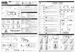
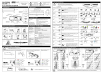
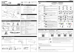
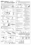
English HR94D1-C1 User Manual (Original) COMPLIED STANDARDS DIN18650-1:2005 EN 12978:2003 EN 16005:2012 EC type examination 44 205 12 414283-001 1. DESCRIPTION WARNING ! Note Disregarding this symbol may result in serious injury or death Special attention is required when this symbol is shown ! CAUTION EN16005 Disregarding this symbol may result in injury or damage to equipment Φ10mm(0.39") -Wiring hole Accessories DIP Switch Potentiometer (Sensitivity Volume) 1 2 40mm (1.57") 15mm 20mm (0.59") (0.79") Dip Switch X Presence Timer Installation Instruction 210mm(8.27" ) Monitor Mode Mounting Screws (2 pcs.) Indicator LED Mounting height of 3 m (9.8ft) or lower Ensure there are no moving objects in the detection zone If the sensor is exposed to excessive rain install with a Hotron weather cover Model Name Detection Method Installation Height Supply Voltage Power Consumption 3m (9.8ft) If possible ensure no accumulation of snow or water on the floor. Ensure no condensation gets onto the sensor. A Ensure the minimum of reflected sunlight from the floor B Use different frequency settings for sensors in close proximity HR94D1-C1 Active Infrared Detection 3[m] (9.8[ft]) Max AC/DC 12 to 24 [V] ±10% Red & Black (Nonpole) AC12V-1.8 [VA] (Max) AC24V-2.8 [VA] (Max) DC12V-100 [mA] (Max) DC24V-60 [mA] (Max) Approx 0.5s 0.1s ~ 0.2s Output Holding Time Response Time Presence Timer DIP Switch #1, #2 (2, 30, 60, ∞ seconds) Output Open collector 7.5[mA](Max) Resistor Load DIP SW Normally Drive (Normally Close) #6 : N.C. Open on Detection DIP SW Normally Open #6 : N.O. Drive on Detection (Close on Detection) Test Input Opto coupler(NPN) Voltage:55 [VDC] Max. Current:50 [mA] Max. Dark Current : 100 [nA] Max. (Resistance load) Non-Test : DC12 to 24 V / Test : Open 6 [mA] Max.@ 24 [VDC] Operating Temperature -20 to +60 [Deg.C],(-4 to 140 Deg.F) Operating humidity Below 80% ☆ N.C. 6 ① Drill mounting (3.5mm φ ) a n d wiring (10mmφ) holes. D 3 4 ☆ Normal 3 4 Snow ☆ N.C. 5 (Drive) N.O. 6 A low reflected infrared signal is indicated by a slow flashing Red/Green LED. To ignore this low reflection error state, set this dip switch to “Low Reflection”(ON). EN16005 To comply with EN16005 set to “Normal” ☆ Normal Reflection Diagnostics 7 Test Input Setting from Door Controller When connected to a door controller without a TEST input, set to “OFF”. When connected to a door controller with a TEST input, set to “ON” Refer to [11.Timing Chart of events]. ☆ OFF 8 EN16005 Transmitter 7 ON 0v 7 Detection Area Width Adjustment FRONTAL VIEW/DETECTION AREA Area Mask Adjustment 0 IP54 Category 2 , performance level C for presence detection according to EN ISO 13849-1:2008 1.0m 3.3' Weight 0.190kg, ( 0.42lbs.) Accessories Cable : 2.5m (8ft.) Mounting Screw (2pcs) Mounting Template User Manual 1.5m 4.9' [ 5 degree ] setting NARROW WIDE [ 0 degree ] setting MIN (m)2.0 1.5 1.0 0.5 6.6' 4.9' 3.3' 1.6' 2.0m 6.6' 2.5m 8.2' 3.0m 9.9' Max Area Without TEST OFF 0v 2.5m 2.0m 1.5m 1.0m 0.5m 0m 8.2' 6.6' 4.9' 3.3' 1.6' 0' IP Rate IR Spot With TEST Without TEST 8 SIDE VIEW/DETECTION AREA 0.5m 1.6' Min Area 0.5 1.0 1.5 1.6' 3.3' 4.9' 2.0 6.6' 2.0 1.5 1.0 0.5 6.6' 4.9' 3.3' 1.6' 0 0.5m 1.6' 1.0m 3.3' 1.5m 4.9' 2.0m 6.6' 2.5m 8.2' 3.0m 9.9' ③ Fasten unit with mounting screws rovided. ! CAUTION The above illustrated detection areas represent the actual position of the infrared beams. The actual detection area observed will vary depending on the sensor installation environment, object been detected and sensor settings. Please ensure that the detection area is set to conform to EN16005. 9. APPLYING POWER 50mm BEFORE APPLYING POWER, READ AND FOLLOW THESE INSTRUCTIONS: Sensor’s Cable ON EN16005 8 Cable ④ -2 Wiring to a door controller that cannot test the sensor. Red Black Yellow AC/DC Power 12 to 24 [V] (Non Pole) ±10% Blue(-) Gray Emitter Brown Test-N Collector Sensor’s Cable Cable Output Test-P Test Input OFF Set to “ON” to comply with EN16005 ⑥ Set desired sensor parameters as noted in Sections 7 & 8. Section 7. DIP Switch Settings Section 8. Detection Area Width andDepth Adjustment 0.5 1.0 1.5 2.0 1.6' 3.3' 4.9' 6.6' » The body of the sensor can be rotated from 0º~5º(3 Steps) ② Remove cover using a coin. ④-1 Wiring to a door controller that can test the sensor. Receiver LED 7 IR Spot ☆ OFF Detection Area Depth Adjustment 2.5m 2.0m 1.5m 1.0m 0.5m 0m 8.2' 6.6' 4.9' 3.3' 1.6' 0' Transmitter Low Ref. ON Set to “ON” to comply with EN16005 Receiver ☆ Normal 8.DETECTION AREA WIDTH AND DEPTH ADJUSTMENT MAX Drilling may cause electric shock. Be careful of hidden wires inside the door engine cover. C 3 4 5 6. MOUNTING & WIRING INFORMATION ! 1 2 1 2 B 3 4 Output logic is defined by this switch. In the N.C. , Opto-Coupler will be driven in the state of nondetection. ∞ 60s 1 2 1 2 ☆A Set to snow in instances where false door activations can result from blowing snow, leaves or rubbish in the door close area. Notice: Specification may be changed without prior notice. WARNING ☆ 30s 2s 5 5. TECHNICAL SPECIFICATIONS 4. MOUNTING PRECAUTIONS Possible Setting Options 3 4 ☆ Normal Output Standby Detecting The detection area is too close to the door Internal Sensor Error Description When more than two sensors are used in close proximity to each other, select different frequency setting for each sensors to prevent interference. ( A + B + C + D = Maximum 4 sensors ) ☆A Frequency 3. LED INDICATORS Area Mask 7 8 1 2 30mm (1.18") Cable Green Red Orange Green/Red blinking alternately 3 4 5 6 The HR94D1-C1 will detect a stationary object only for the time period set by the Presence Timer. The timer will reset and begin if any movement is detected. EN16005 Set the timer to 30sec. or more to comply with EN16005 ☆30s 5mm (0.20") 65mm(2.56") Mounting Holes ON ☆ = Default Setting Mounting Template Connector CAUTION Function 75mm(2.96") 35mm (1.38") ! Setting required to conform with EN16005:2012 2. DIMENSIONS Cover 7. DIP SWITCH SETTINGS ⑤House connectors in the space provided. Red Black Yellow AC/DC Power 12 to 24 [V] (Non Pole) ±10% Blue(-) Gray Emitter do not connect Brown do not connect Collector Output When power is applied, the sensor will read and store the environmental optical parameters. This is necessary for Presence Detection to work properly. ① CLEAR THE AREA OF ANY UNNECESSARY OBJECTS. ② APPLY POWER. ③ WALK AWAY FROM THE DETECTION AREA immediately. ④ DO NOT ENTER DETECTION AREA for 10 SECONDS while the “learning procedure” for Presence detection is carried out. If the sensor can see moving objects during the "learning procedure", the sensor will not proceed to presence detection. ! 8 ⑦ 7. Place cover on sensor and clean the sensor. CAUTION Please DISCONNECT POWER TO THE SENSOR, when carrying out the following work. AFTER THE TASK, APPLY POWER AGAIN. 1. When the floor condition is changed; for example with the addition of of woolen or rubber mat. 2. Adjusting pattern or sensitivity. 10. VERIFICATION OF OPERATION 13. TROUBLESHOOTING 1. After mounting, setting parameters and applying power, walk test unit to verify detection area. 2. If the door does not operate properly, recheck the dip switch settings and pattern adjustments. 3. After rechecking, if there is still a problem, adjust the sensitivity. » Adjust high (clockwise) to increase sensitivity. » Adjust low (counter-clockwise) to decrease sensitivity. CAUTION ! Problems Sensitivity Sensor does not operate High Sensor intermittently detects Possible Cause Sensor Connector Tighten connector or reconnect Power Supply Check that the power supply is properly connected. Sensor is very dusty or covered in water drops, etc. Clean the sensor (do not use thinner or alcohol to clean sensor) Solution Sensitivity too low Sensitivity too high Turn down Sensitivity. Change the frequency to each sensor. Another sensor is too close by As the detection area is variable depending on clothes, floor material and sensitivity adjustment, please confirm that the detection area demanded in EN16005 is secured after adjustment. Sensor detects without obvious reason 11. TIMING CHART OF EVENTS Sensor detects the door movement If the indicator LED is an Orange color, adjust the pattern depth angle away from the door There is a cloth mat in the monitored area. Reactivate the sensor and wait for 10 seconds. Detection pattern too far in front of the door, detecting people passing by Adjust the detection pattern - move it closer to the door The condition of the monitored area is varying. ・Dusty / Dirty ・Snow The condition of the monitored area can change due to heavy dust or dirty, heavy snow or footprints being left in fresh snow, this will cause the malfunction sometimes. Set the “Presence Timer” to a short times. Refer to Section 7. Fast blink Please replace the sensor (Refer to Section 12) The door kept open,although there is Internal error no object in the detection area. (Green/Red LED blinks alternately) POWER OFF NONDETECTION DETECTION Dip Switch #6:N.C. Yellow Blue Yellow Blue Yellow Dip Switch #6:N.O. Yellow Blue Yellow Blue Yellow NONDETECTION DETECTION as response to TEST Yellow Yellow Yellow Blue Blue Yellow Blue Blue Yellow Blue Blue TEST RESPONSE T1 Test Input T2 NON-TEST Gray TEST Sensor Gray NON-TEST Sensor Gray Brown Break the current flow on test state. Brown Supplying DC12 to 24V, make current flow from Gray to Brown. T1: 8~14[mSec] App. Slow blink Low reflection error or Test line disconnection (Refer to Section 7, Section 12) 14. HR94D1-C1 EC DECLARATION OF CONFORMITY NONDETECTION Yellow Blue Blue Turn up sensitivity Alter the detection pattern by changing sensor angle, and/or pattern width adjustments Detection pattern in the wrong position Compiler of Technical File (EC Community) David Morgan Hotron Ireland Ltd 26 Dublin Street, Carlow, Ireland Ph: +353-(0)59-9140345 Fax: +353-(0)59-9140543 Description of Product: HR94D1-C1 is designed to monitor the side screen of the automatic door. Technology used is Active Infrared Technology Harmonized Standards Used: EN ISO 13849-1:2008 Other Technical Standards Used: DIN 18650-1:2005, EN16005:2012 Above EC Type Directives Certified by: TUV NORD CERT GmbH 30519 Hannover, Germany Identification No: 0044 Declaration made by Kaoru Musya General Manager. Honda Electron Location of Declaration Honda Electron Co., LTD. 1-23-19 Asahi-Cho, Machida-City, Tokyo, Japan Date 9th of Nov 2012 Directives Fulfilled: Sensor DIRECTIVE 2006/42/EC DIN 18650-1:2005 Powered pedestrian doors Part 1: Product requirements chapter 5.7.4 EN12978:2003 Industrial, commercial and garage doors and gates - safety devices for power operated doors and gates - Requirements and test methods. EN62061:2005 Functional safety of electrical/electronic/programmable electronic safety-related systems. EN ISO 13849-1:2008 Safety of machinery - Safety-related parts of control systems. EN 16005:2012 EC type examination 44 205 12 414283-001 Brown T2: 9~15 [mSec]App. < Disclaimer > The manufacturer cannot be held responsible for below. 1. Misinterpretation of the installation instructions, miss connection, negligence, sensor modification and inappropriate installation. 2. Damage caused by inappropriate transportation. 3. Accidents or damages caused by fire, pollution, abnormal voltage, earthquake, thunderstorm, wind, floods and other acts of providence. 4. Losses of business profits, business interruptions, business information losses and other financial losses caused by using the sensor or malfunction of the sensor. 5. Amount of compensation beyond selling price in all cases. 12. SELF DIAGNOSTICS ERRORS When the sensor has the self-test error, the green/red LED blinks alternately. The blinking cycle is different, according to the kinds of the error as follows. LED ■Fast Blink ( Green/Red ) Green Cause Solution Response to TEST DIP Switch #6 : N.O. Internal error Please replace the sensor. Red ■Slow Blink ( Green/Red ) Green Red ■Slow Blink ( Red/Red/Green ) Green Set the sensitivity to maximum, Low reflection and then reactivate the sensor. If the error continues, set level DIP Switch #7 “ON” . Output on Error State No Response DIP Switch #6 : N.C. Yellow Blue Yellow Blue Test line Please confirm the connection disconnection of the test line. Red R Manufacturer HOTRON CO.,LTD. 1-11-26 Hyakunin-Cho, Shinjuku-Ku, Tokyo, Japan Phone: +81-(0)3-5330-9221 Fax: +81-(0)3-5330-9222 URL: http://www.hotron.com SALES Europe Hotron Ireland Ltd. 26 Dublin Street (2nd Floor), Carlow, Ireland Phone: +353-(0)59-9140345 Fax: +353-(0)59-9140543 URL: http://www.hotron.com MP-10139 '13.01 PRINTED IN JAPAN