1
Rugged, Reliable, Mobile, Secure
TM
Data Express DE100 Ultra320 SCA
Removable SCSI Wide Ultra320 Drive Enclosure with 80-Pin SCA Interface
NOTES: For SCSI Ultra320 operation, the DE100 Ultra320 SCA requires Ultra320
drives, Ultra320 HBA, and Ultra320-compliant cabling (internal and external).
DE100 Ultra320 SCA can support Ultra320 implementations with a maximum of fifteen
(15) Ultra320 drives (Ultra320 repeater may be required).
DE100 Ultra320 SCA receiving frames are indicated by their BLUE LED, while the
Ultra320 DE100 carriers are indicated by the Ultra320 logo.
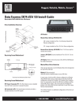
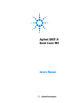
Factory-Installed Jumpers: There are two factory-installed jumpers on
W1. This jumpers are located on Pins 9 & 10 and 19 & 20.
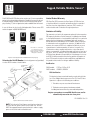
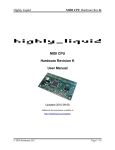
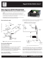
Drive Installation Assembly
Figure 1: Drive Installation Overview
NOTE: Do not remove these jumpers!
Receiving Frame
Motherboard
Drive Cover
(provided)
DC Power
Connector
(P1)
GND
68-Pin I/O
Connector
(J3)
Buzzer
Receiving
Frame
Drive
(not included)
Option Pin
Connector
(W1)
Drive
Carrier
= Pin 1
Drive Carrier
Board
Front-Mounted
Fan
Remote ID Select
#6-32-Phillips
F.H. Screw
(6 Total)
{
ID0
ID1
ID2
ID3
Note: Installation of drive cover is necessary for proper fan air flow!
Factory-Installed
Jumpers
(do not remove)
Receiving Frame Motherboard
Option Pin Connector (W1)
Figure 2: Receiving Frame Motherboard (rear view)
Remote Unit ID Selection: Pins 1-8 of this connector are provided
for remote unit SCSI ID selection through the computer system.
Remote ID selection requires that the unit ID switch located on the
inside of the receiving frame be set to “0” (onboard ID selection is set
with a switch located on the inside of the receiving frame).
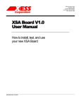
The Ultra320 DE100 drive carrier contains one (1) front-mounted drive carrier fan for enhanced heat dissipation. Should the fan ever fail, the unit ID
number indicator (located on the front of the receiving frame) will display a
flashing “F” (refer to figure below) and an audible alarm will sound.
Remote Activity LED (RLED): Pins 17 & 18 provide power for a
remote LED device activity indicator.
In case of failure, the fan is easily field-replaceable. Refer to the full
version of the DE100 Ultra320 SCA User’s Guide for further information.
1-800-260-9800
www.CRU-DataPort.com
Rugged, Reliable, Mobile, Secure
TM
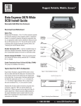
The DE100 Ultra320 SCA drive carrier contains one (1) front-mounted drive
carrier fan for enhanced heat dissipation. Should the fan ever fail, the unit
ID number indicator (located on the front of the receiving frame) will display a flashing “F” (refer to figure below) and an audible alarm will sound.
In case of failure, the fan is easily field-replaceable. Please contact CRU
technical support at (800) 260-9800 ext.4.
Activity
Indicator
Carrier Removed
from Receiving
Frame
Carrier Installed
(unlocked)
Carrier Installed
(locked)
The number “2” shown above
is for illustration purposes
only. It can be any valid unit ID
number. The letter “u” and “F”
will appear as illustrated.
Fan Failure
Figure 3: Receiving Fame Unit ID Number and Activity Display
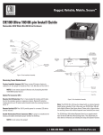
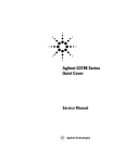
Selecting the Unit ID Number: Use the alignment tool (provided)
to select the ID number of the disk drive.
Lock and
DC Power
Switch
CRU-DataPort (CRU) warrants the Data Express DE100 to be free
of significant defects in material and workmanship for a period of
five years from the original date of purchase. CRU’s warranty is
nontransferable and is limited to the original purchaser.
Limitation of Liability
The warranties set forth in this agreement replace all other warranties.
CRU expressly disclaims all other warranties, including but not limited
to, the implied warranties of merchantability and fitness for a particular
purpose and non-infringement of third-party rights with respect to
the documentation and hardware. No CRU dealer, agent or employee
is authorized to make any modification, extension, or addition to this
warranty. In no event will CRU or its suppliers be liable for any costs
of procurement of substitute products or services, lost profits, loss
of information or data, computer malfunction, or any other special,
indirect, consequential, or incidental damages arising in any way out of
the sale of, use of, or inability to use any CRU product or service, even
if CRU has been advised of the possibility of such damages. In no case
shall CRU’s liability exceed the actual money paid for the products at
issue. CRU reserves the right to make modifications and additions to
this product without notice or taking on additional liability.
Certification
Unit ID Number
Display
ID Select Rotating
Switch
Limited Product Warranty
EMI Standard: FCC Part 15 Class B, CE
EMC Standard: EN55022, EN55024
Front of
Unit
FCC Certification
This device has been tested and found to comply with the limits
for a Class B digital device, pursuant to Part 15 of the FCC rules.
Operation is subject to the following two conditions:
Drive Carrier
Guide
Receiving
Frame
1. This device may not cause harmful interference.
Drive Carrier
(removed)
2. This device must accept any interference received; including interference that may cause undesired operation.
Register your product at www.CRU-DataPort.com and be
automatically entered to win a free prize!
A7-100-0003 Rev. 3.0
Figure 4: Unit ID Select Switch Location
NOTE: The lock on the Data Express receiving frame functions
as a lock and a DC power switch for the carrier unit. The lock
MUST be engaged (turned counterclockwise) in order to supply
power to the carrier and installed drive unit.
1-800-260-9800
www.CRU-DataPort.com