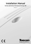
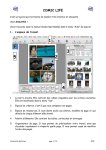
1
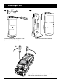
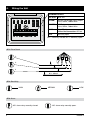
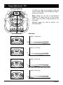
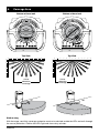
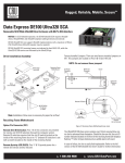
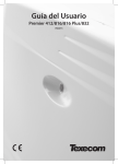
Installation Manual
Prestige External TD
INS352-2
1.
Accessing the Unit
1
2
Remove the top cap and loosen screw
(screw retained in wall plate).
Push up head unit and remove.
3
Use a flat head screwdriver to lever out both
sides of the terminal cover as shown.
1
INS352-2
2.
Choosing a Location
• Mounting height 1.0 - 1.4m (nominal 1.2m), measured to middle of unit.
•Mount perpendicular to ground.
✓
Parallel
1.0 - 1.4m
• Try to avoid direct sunlight.
• Avoid pointing at swaying bushes/trees and swaying clothes on a clothes line.
✗
✗
• Try to install the detector so its detection area is
terminated by building/fences etc. This will reduce
the effect of range variation caused by environmental
changes.
•
In the detection area try to avoid reflective surfaces
such as standing water, swimming pools or polished
floors as this can cause the detectors range or coverage
to vary as reflected signals may be seen.
INS352-2
✗
2
3.
Mounting the Unit
Front View
WALL MOUNTING
For wall mounting, the
cable should be brought
through the wall into the
cable entry hole.
Cable Entry
REAR TAMPER
To enable the rear tamper, the breakaway keyhole
section must be securely fixed to the mounting surface.
Rear View
Cable Entry
SURFACE WIRING
For surface wiring, use the appropriate knockout in the
top or bottom of the unit. If wiring from the top, use the
knockouts in the top cap and run the cable down the
cable channels and into the unit as shown.
Knockout in Top Cap
Cable
Channels
Cable Entry
Conduit Entry
3
INS352-2
Pole Mount Bracket Mounting
POLE MOUNTING
Using the pole mount kit (available separately) the unit can be mounted on poles with an outside
diameter of 20 - 57mm. Assemble the kit around the pole as shown and tighten the 4 bolts. Hook the
detector wall plate onto the kit and secure the remaining 2 bolts through the lower mounting holes.
1
2
ø 20 - 44mm
x4
x1
ø 45 - 57mm
x4
3
5
x3
4
INS352-2
4
4.
Wiring the Unit
TERMINAL BLOCK
12V & 0V:
9-16 VDC.
ALARM:
NO/NC (selectable) relay output.
18 Ω, 50VDC, 100mA Max.
TAMPER:
NC Relay output.
18 Ω, 50VDC, 100mA Max.
RLED:
0V: LED off.
12V or No Connection: LED on.
AUX:
NC relay input.
NC = Normally Closed, NO = Normally Open
JP1: Pulse Count
2
3
4
0.3 - 3.0m/s
JP2: Sensitivity
HIGH
MEDIUM
LOW
JP3: Alarm
NC: alarm relay normally closed.
5
NO: alarm relay normally open.
INS352-2
JP4: LED
JP5: MODE
Day/Night Mode
Detector is always operating.
Night Mode
Detector only operates at night.
JP6 & JP7: END OF LINE JUMPERS
JP7
Selects the End-of-Line
resistance. Equivalent
to wiring a resistor of
the selected value as
shown.
ALARM - JP7
JP6 Selects the resistance across the alarm
relay. Equivalent to wiring a resistor of the
selected value as shown.
TAMPER - JP6
JP8 & JP9: see Auxiliary section (page 9)
INS352-2
6
5.
Range Adjustment - PIR
Bottom of head unit
To adjust the range of the detector, rotate the
circular section shown until the desired range is
shown in the window.
Note: Range can vary due to environmental
conditions. To reduce the risk of false alarms
always select the lowest range possible for the
installation.
Specified ranges are valid for nominal 1.2m
mounting height.
Selected Range
Side View
Position - 12m Coverage
1.2m
0m
0m
2m
4m
6m
8m
10m
12m
8m
10m
12m
8m
10m
12m
8m
10m
12m
Position - 8m Coverage
1.2m
0m
0m
2m
4m
6m
Position - 5m Coverage
1.2m
0m
0m
2m
4m
6m
Position - 2m Coverage
1.2m
0m
0m
7
2m
4m
6m
INS352-2
6.
Coverage Area
Bottom of head unit
Bottom of head unit
Top View
12m
10m
8m
6m
4m
2m
0m
Top View
4m
2m
6m
8m
10m
12m
12m
10m
8m
6m
4m
2m
0m
2m
4m
6m
8m
10m
12m
0m
0m
2m
2m
4m
4m
6m
6m
8m
8m
10m
10m
12m
12m
Active
detection
coverage
Active
detection
coverage
45˚
45˚
90˚
90˚
90˚
Walk-testing
With the range, sensitivity, coverage and pulse count set as desired, enable the LEDs and walk-through
the area of protection. Confirm the LEDs light and alarm relay activates.
INS352-2
8
7.
Auxiliary Input
With the Auxiliary input enabled (JP8), a second detector with a normally
closed relay output can be connected to the Prestige External detector to give
directional detection. The order of activation required to give an alarm signal is
set by the direction jumper (JP9).
When this is set to ‘1st’ the auxiliary detector must be activated first followed by
the Prestige External detector within 1 minute to give a valid alarm signal.
With the jumper set to 2nd, the Prestige External detector must be activated
followed by the auxiliary detector within 1 minute.
If directional detection is not required, disable the auxiliary input using JP8.
AUX
ALARM
1st
NO
ALARM
OFF
JP9
ALARM
1st
NO
ALARM
2nd
AUX
2nd
ON
Prestige External PIR
NO
ALARM
JP9
JP8
Prestige External PIR
NO
ALARM
Quality Assurance
Warranty - 2 year replacement warranty.
The Prestige External unit is designed to detect the movement of
an intruder and activate an alarm control panel. As the Prestige
External unit is not a complete alarm system, but only a part
thereof, Texecom cannot accept responsibility or liability for any
damages whatsoever based on a claim that the Prestige External
unit failed to function correctly.
Due to our policy of continuous improvement Texecom reserves
the right to change specification without prior notice. All
specifications are measured at 20ºC (68ºF).
9
Cer tificate Number: FM 35285
MADE IN ENGLAND
The Prestige External detector is protected
by UK & International Designs.
Prestige is a Trademark of Texecom Ltd.
INS352-2
8.
Specifications
Mounting Height:
1.0 - 1.4m, 1.2m nominal
Supply Voltage:
9-16 VDC
Current Drain (typical):
28mA
Detection Method:
Dual, non-overlapping, digital PIR
Range:
12m max. Adjustable to 8m, 5m and 2m
Alarm Output:
NC/NO selectable relay. Rated 50VDC, 100mA, 18Ω
Tamper Detection:
Wall and case. Sealed non-mechanical switch.
Tamper Output:
NC relay. Rated 50VDC, 100mA, 18Ω
LED Indication:
Red alarm indication
Environmental Protection:
IP65
Waterproof Coating:
Conformal
EMC:
EN 50130-4: 1996, A1 1998, A2 2002. EN 55022: Class B
9.
Physical Specifications
89mm
86.5mm
-35°C (-31°F) to
+60°C (+140°F)
250mm
-35°C (-31°F) to
+55°C (+131°F)
550g (20oz)
approx.
INS352-2
10
Texecom Limited, Bradwood Court, St. Crispin Way, Haslingden, Lancashire BB4 4PW, England.
Technical Support:
UK Customers Tel: 08456 300 600
(Calls charged at 3.36 pence per minute from a BT landline. Calls from other networks may vary.)
International Customers Tel: +44 1278 686197
Email: [email protected]
© Texecom Limited 2009.
INS352-2
B20090720