1
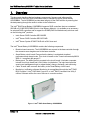
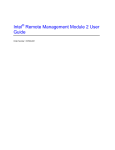
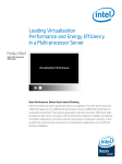
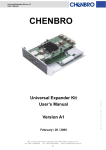
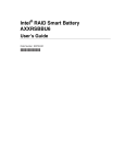
Intel® RAID Smart Battery AXXRSBBU4 Technical Product Specification Intel order number E20188-002 Revision 1.2 July 2008 Enterprise Platforms and Services Marketing Revision History Intel® RAID Smart Battery AXXRSBBU4 Technical Product Specification Revision History Date April 2007 Revision Number 0.8 Modifications Initial Release July 2007 1.0 Update AXXRSBBU4 picture December 2007 1.1 Update supported RAID devices July 2008 1.2 Update Battery pack information Disclaimers INFORMATION IN THIS DOCUMENT IS PROVIDED IN CONNECTION WITH INTEL® PRODUCTS. NO LICENSE, EXPRESS OR IMPLIED, BY ESTOPPEL OR OTHERWISE, TO ANY INTELLECTUAL PROPERTY RIGHTS IS GRANTED BY THIS DOCUMENT. EXCEPT AS PROVIDED IN INTEL'S TERMS AND CONDITIONS OF SALE FOR SUCH PRODUCTS, INTEL ASSUMES NO LIABILITY WHATSOEVER, AND INTEL DISCLAIMS ANY EXPRESS OR IMPLIED WARRANTY, RELATING TO SALE AND/OR USE OF INTEL PRODUCTS INCLUDING LIABILITY OR WARRANTIES RELATING TO FITNESS FOR A PARTICULAR PURPOSE, MERCHANTABILITY, OR INFRINGEMENT OF ANY PATENT, COPYRIGHT OR OTHER INTELLECTUAL PROPERTY RIGHT. Intel products are not intended for use in medical, life saving, life sustaining, critical control or safety systems, or in nuclear facility applications. Intel might change specifications and product descriptions at any time, without notice. Designers must not rely on the absence or characteristics of any features or instructions marked "reserved" or "undefined." Intel reserves these for future definition and shall have no responsibility whatsoever for conflicts or incompatibilities arising from future changes to them. The Intel® RAID Smart Battery AXXRSBBU4 may contain design defects or errors known as errata which may cause the product to deviate from published specifications. Current characterized errata are available on request. Intel is a trademark or registered trademark of Intel Corporation or its subsidiaries in the United States and other countries. *Other names and brands may be claimed as the property of others. Copyright © 2007-2008, Intel Corporation, Portions Copyright LSI, Inc. ii Revision 1.2 Intel order number E20188-002 Intel® RAID Smart Battery AXXRSBBU4 Technical Product Specification Table of Contents Table of Contents 1. Overview ............................................................................................................................... 1 2. Hardware ............................................................................................................................... 3 2.1 Electrical and Mechanical Details ............................................................................ 3 2.2 Functional Block Diagram........................................................................................ 4 2.3 Board-to-board connector........................................................................................ 4 2.4 Connecting Cable .................................................................................................... 5 2.5 Circuit Logic Board .................................................................................................. 5 2.6 Battery Pack ............................................................................................................ 6 2.6.1 Battery Life and Data Retention Time...................................................................... 6 2.6.2 Battery States .......................................................................................................... 6 3. RAID Firmware Interaction .................................................................................................. 8 4. Software ................................................................................................................................ 9 4.1 Intel® RAID BIOS Console 2 .................................................................................... 9 4.2 Intel® RAID Web Console 2 ..................................................................................... 9 4.3 Intel® RAID Command Line Utility 2......................................................................... 9 Revision 1.2 Intel order number E20188-002 iii List of Figures Intel® RAID Smart Battery AXXRSBBU4 Technical Product Specification List of Figures Figure 1. Intel® RAID Smart Battery AXXRSBBU4 ....................................................................... 1 Figure 2. Block Diagram ............................................................................................................... 4 List of Tables Table 1. Electrical and Mechanical Details ................................................................................... 3 Table 2. Board-to-Board Interface Connector Pin-out .................................................................. 4 Table 3. Interface Connector Pin-out ............................................................................................ 5 iv Revision 1.2 Intel order number E20188-002 Intel® RAID Smart Battery AXXRSBBU4 Technical Product Specification 1. Overview Overview This document describes the key hardware components, firmware, and software utility requirements for the Intel® RAID (Redundant Array of Inexpensive Disks) Smart Battery AXXRSBBU4. The AXXRSBBU4 provides data integrity for the RAID solution by ensuring that the data passing through the cache is written to the hard drives. The Intel® RAID Smart Battery AXXRSBBU4 supports RAID controllers that use a standard 256 MB or 512 MB DDR2 DIMM (Dual In-Line Memory Module). It is available as an accessory for selected RAID controllers and to support the ROMB (RAID-on-Motherboard) solutions used on the following Intel® products: Intel® Server RAID Controller SRCSASRB Intel® Server RAID Controller SRCSATAWB Intel® Server System S7000FC4UR with a SAS riser card The Intel® Smart Battery AXXRSBBU4 contains the following components: Board-to-board connector: The AXXRSBBU4 can connect to the base controller through the connector as a daughter card to the base controller. Smart Battery circuit board: Ensures that the battery is maintained at optimal performance and charge levels. This circuit is based on the Texas Instruments bq2060A SBS v1.1-compliant gas gauge IC*. Battery pack: The battery pack is mounted to the circuit board. It includes a separate, internal circuit logic board and LiON (Lithium Ion) batteries. The logic board provides sensing and management logic to support battery charge, discharge, and monitoring. Cable: A small cable connects the battery to the Smart Battery circuit board. Monitoring / notification software: Monitoring is accomplished through the Intel® RAID BIOS Console 2, Intel® RAID Web Console 2, or Intel® RAID Command Line Utility 2 utilities. Software notifies the user of failures or corrective actions. Figure 1. Intel® RAID Smart Battery AXXRSBBU4 Revision 1.2 Intel order number E20188-002 1 Overview Intel® RAID Smart Battery AXXRSBBU4 Technical Product Specification The battery pack charges automatically and communicates battery status information, such as voltage, temperature, and current to the host computer system. Because it is faster to write data to the RAID adapter’s cache memory than it is to write it directly to a storage device, data is first written to the cache memory. These write operations are completed quickly at the software application level. The RAID controller then writes the cached data to the storage device when system activity is low or when the cache is full. This method of writing data carries a risk. Cached data on the RAID controller can be lost if the AC power fails before the data is written to the storage device. The Intel® RAID Smart Battery AXXRSBBU4 mitigates this risk by providing battery power to the RAID controller if AC power is lost. The Intel® RAID Smart Battery AXXRSBBU4 monitors the voltage level of the DRAM modules on the RAID controller. If the voltage drops below a predefined level, the Smart Battery switches the memory power source from the RAID controller to the battery pack. The battery pack provides power for the memory until the voltage returns to an acceptable level, at which time the Smart Battery circuit board switches the power source back to the RAID controller. Cached data is then written to the storage devices with no loss of data. The Smart Battery provides additional fault tolerance when used with a UPS. The battery pack cache-memory hold time depends on the size and configuration of the RAID controller memory. Retention time depends on memory capacity and the number of memory components on the DIMM to support the capacity. An estimated battery backup retention time is 72 hours (three days). 2 Revision 1.2 Intel order number E20188-002 Intel® RAID Smart Battery AXXRSBBU4 Technical Product Specification 2. Hardware 2.1 Electrical and Mechanical Details Hardware Table 1. Electrical and Mechanical Details Feature Data retention Up to 72 hours Description Chemistry LiON Dimensions Maximum 3.595-inches by 2.055- inches Weight 95 Grams Operating temperature 10 to 45° C dry bulb temperature (the maximum dry bulb temperature shall be derated by 3.3° C per 1000 m above 500 m) Operating humidity 20% - 80 %, non-condensing Storage temperature Greater than 90 days at 0 to 30 degrees Celsius 30 to 90 days at 0 to 40° C Less than 30 days at 0 to 50 degrees Celsius Storage humidity 20% to 80 %, non-condensing Battery capacity 1050 mAH Voltages Nominal OCV: 3.7 V Fast charge current 512 mAH Battery voltage conditioning Less than 3.0 V Battery charge time Typical: ~6 hours to charge from 3.6 V OCV to 4.2 V OCV Worst case: 10 hours if pack is completely depleted of charge Date retention times 72 hours for 256 MB standard cache, using 256 Mbit x 16 DDR2 MTBF (electrical components) 3,251,335 hours at 40° C Battery shelf life 1 year Battery operational life 500 recharges cycles. Note: Intel recommends replacing the battery yearly. Revision 1.2 Intel order number E20188-002 3 Hardware 2.2 Intel® RAID Smart Battery AXXRSBBU4 Technical Product Specification Functional Block Diagram Figure 2. Block Diagram 2.3 Board-to-board connector The Intel® RAID Smart Battery AXXRSBBU4 is connected through the board-to-board connector. Table 2. Board-to-Board Interface Connector Pin-out 4 Pin 1 Signal Name VBB_DDR_MEM Output Signal Type 2 GND GND 3 +12 V Input 4 GND GND 5 PFAIL# Output 6 BBEN Input 7 +1.8V Input 8 BBU_DET Output 9 3.3v_AUX Input 10 GND GND 11 GND GND 12 +3.3V Input 13 SCL Input / output 14 GND GND 15 SDA Input / output 16 BBSTATUS Output 17 GND GND 18 BBSTROBE Input 19 GND Input 20 VBB_DRR_MEM Output Revision 1.2 Intel order number E20188-002 Intel® RAID Smart Battery AXXRSBBU4 Technical Product Specification 2.4 Hardware Connecting Cable A 5-pin connector cable connects the battery pack to the Smart Battery circuit board. Table 3. Interface Connector Pin-out 2.5 Pin 1 Signal Name VBATP I/O Input Description Battery positive terminal 2 THERMISTOR SENSE Output 3 GND Input 4 SCL Output I2C Clock for pack monitoring 5 SDA Input I2C Data for pack monitoring Sense contact of the thermistor Battery negative terminal Circuit Logic Board The Intel® RAID Smart Battery AXXRSBBU4 is based on the Texas Instruments bq2060A SBS v1.1-compliant Gas Gauge IC*. The SBS v1.1 IC maintains an accurate record of the available charge. It monitors the amount of charge input in to or removed from the Intel® RAID Smart Battery AXXRSBBU4 to determine the battery capacity. The bq2060A measures battery voltage, temperature, and current; estimates battery selfdischarge; and monitors the battery for low-voltage thresholds. It measures charge and discharge activity by monitoring the voltage across a small-value series sense resistor between the battery’s negative terminal and the negative terminal of the battery pack. The battery charge is determined by monitoring this voltage and correcting the measurement for environmental and operating conditions. See the Texas Instruments website for more information about the Texas Instruments bq2060A SBS v1.1-compliant Gas Gauge IC*. The following lists the Intel® RAID Smart Battery features: The Smart Battery circuit integrated into the battery pack Reduced host CPU intervention Shares I2C bus with the onboard EEPROM (Electronically Erasable Programmable Read-Only Memory) for memory Real-time battery status information Low charge warning Instantaneous voltage, current, and temperature warnings Battery charge percentage remaining and at-rate information Broadcasts event alarms to the host: - Out-of-temperature Terminate charge Terminate discharge Revision 1.2 Intel order number E20188-002 5 Hardware 2.6 Intel® RAID Smart Battery AXXRSBBU4 Technical Product Specification - Low capacity Manufacturing information Smart Charger Protocol for improved battery maintenance, calibration, and charging performance Battery Pack 2.6.1 Battery Life and Data Retention Time ® The Intel RAID Smart Battery software utilities use a counter to show the number of times the battery has been recharged. When you replace the Intel® RAID Smart Battery AXXRSBBU4, run the Intel® RAID BIOS Console 2 utility and reset this counter to zero for the new battery. Intel recommends that you replace the Intel® RAID Smart Battery AXXRSBBU4 once a year or after 500 recharging cycles, whichever comes first. The Smart Battery has a one-year warranty. The Smart Battery can retain data for about 72 hours (three days). This is approximate and can vary due to several factors, including capacity of the battery pack, the battery load, the ambient temperature, the age of the battery, and the number of discharge cycles associated with the battery. 2.6.2 Battery States The battery pack includes sensing logic that checks the battery voltage levels and recognizes the battery state. 2.6.2.1 Initialized State The battery is in the initialized state during a normal power-up sequence. In RAID firmware, there are two levels of initialization: During boot loader execution During a RAID firmware boot 2.6.2.2 Discharging State The battery voltage is drained as part of a relearn cycle. 2.6.2.3 Fully Charged State A battery that is not fully charged has a low-voltage level that indicates the level of charge. Charging begins when the battery logic detects low voltage and power is supplied. Once a new battery is fully charged, a relearn cycle is initiated. Relearn is the process of taking a fully charged battery through the discharge-charge cycle to update the gas gauge capacity parameters. The relearn cycle takes up to 24 hours to fully-discharge and recharge the battery pack. After the relearn cycle is completed, information from the battery accurately provides the state of charge, capacity, and other parameters. 6 Revision 1.2 Intel order number E20188-002 Intel® RAID Smart Battery AXXRSBBU4 Technical Product Specification Hardware These parameters determine the health of the battery. The relearn cycle can be set at a user-definable interval. The default is a one-month (30 days) interval. A relearn cycle is initiated when a new battery is inserted, even if the battery was fully charged previously. Some applications can start a relearn, or a relearn can be manually started. 2.6.2.4 Fully-discharged State The fully-discharged state is detected as a low voltage parameter. The charger detects a fullydischarged battery state and starts charging the cells when sufficient power is available, and when the firmware has completed initializing the pack. Revision 1.2 Intel order number E20188-002 7 RAID Firmware Interaction 3. Intel® RAID Smart Battery AXXRSBBU4 Technical Product Specification RAID Firmware Interaction The RAID firmware detects the battery status and logs the following events: 8 Battery is present Battery is not present A new battery is detected Battery has been replaced Battery temperature is high Battery voltage is low Battery is charging Battery is discharging Battery voltage is normal Battery needs replacement: SOH bad Battery needs replacement: Battery is three years old Battery needs replacement: Charger is not working Relearn has started Relearn is in progress Relearn completed Relearn timed out Relearn pending: Battery is under charge. Relearn postponed Relearn will start in four days Relearn will start in two days Relearn will start in one day Relearn will start in five hours Revision 1.2 Intel order number E20188-002 Intel® RAID Smart Battery AXXRSBBU4 Technical Product Specification 4. Software 4.1 Intel® RAID BIOS Console 2 Software The system BIOS loads the RAID option ROM that is resident on the RAID controller flash. Press <Ctrl> + <G> when prompted during POST (Power On Self Test) to use this utility. The option ROM checks for the presence of the battery and informs the user if the battery is missing or not fully charged. The Intel® RAID BIOS Console 2 utility can be used to monitor charge cycle count and voltage levels. It displays the number of fast battery charges and discharges. 4.2 Intel® RAID Web Console 2 The Intel® RAID Web Console 2 is an operating system-based utility for supported Microsoft Windows* and Linux* operating systems. This utility can monitor battery status, charge level, and the number of recharge cycles. 4.3 Intel® RAID Command Line Utility 2 The Intel® RAID Command Line Utility 2 is a text-based command-line utility (CLU) for Microsoft Windows* and Linux* operating systems. It shows battery status and can be used to initiate a relearn. Revision 1.2 Intel order number E20188-002 9