1
Intel® Remote Management Module 2 User
Guide
Order Number: E27084-001
Disclaimer
Information in this document is provided in connection with Intel® products. No license, express or implied, by estoppel or
otherwise, to any intellectual property rights is granted by this document. Except as provided in Intel’s Terms and Conditions of Sale
for such products, Intel assumes no liability whatsoever, and Intel disclaims any express or implied warranty, relating to sale and/or
use of Intel products including liability or warranties relating to fitness for a particular purpose, merchantability, or infringement of any
patent, copyright or other intellectual property right. Intel products are not designed, intended or authorized for use in any medical,
life saving, or life sustaining applications or for any other application in which the failure of the Intel product could create a situation
where personal injury or death may occur. Intel may make changes to specifications and product descriptions at any time, without
notice.
Intel server boards contain a number of high-density VLSI and power delivery components that need adequate airflow for cooling.
Intel’s own chassis are designed and tested to meet the intended thermal requirements of these components when the fully
integrated system is used together. It is the responsibility of the system integrator that chooses not to use Intel developed server
building blocks to consult vendor datasheets and operating parameters to determine the amount of airflow required for their specific
application and environmental conditions. Intel Corporation can not be held responsible if components fail or the server board does
not operate correctly when used outside any of their published operating or non-operating limits.
Intel, Intel Pentium, and Intel Xeon are trademarks or registered trademarks of Intel Corporation or its subsidiaries in the United
States and other countries.
* Other names and brands may be claimed as the property of others.
Copyright © 2007, Intel Corporation. All Rights Reserved
Preface
About this Manual
Thank you for purchasing and using the Intel® Remote Management Module 2.
This manual is written for system technicians who are responsible for installing, troubleshooting,
upgrading, and repairing this management module. This document provides a brief overview of
the features of the module, and instructions on how to use and operate the Intel® Remote
Management Module 2.
Manual Organization
Chapter 1 provides a brief overview of the Intel® Remote Management Module 2. In this chapter,
you will find a list of the module features and photos of the product.
Chapter 2 provides instructions on installing the module. Use this chapter for step-by-step
instructions.
Chapter 3 provides instructions on using the utility – Psetup, which can be used to identify the
IP address of the Intel® RMM2.
Chapter 4 provides instructions on using the utility KiraTool, which is a command line
application used to probe, manage, and configure the Intel® RMM2.
Chapter 5 provides an introduction to the Intel® RMM2 and the Web interface used for
connections.
Chapter 6 outlines the steps to use the Remote Console (KVM) connection.
Chapter 7 covers all the menu options available on the Web interface.
Intel® Remote Management Module 2 User Guide
iii
Contents
Safety Information
WARNING
Before working with your Intel® RMM2 product, whether you are using this guide or any other
resource as a reference, pay close attention to the safety instructions. You must adhere to the
assembly instructions in this guide to ensure and maintain compliance with existing product
certifications and approvals. Use only the described, regulated components specified in this
guide. Use of other products / components will void the UL listing and other regulatory
approvals of the product and will most likely result in noncompliance with product regulations in
the region(s) in which the product is sold.
WARNINGS
System power on/off: The server power button DOES NOT turn off
the system power or Intel® RMM2 power. To remove power from the
Intel® RMM2 you must unplug the server AC power cord from the wall
outlet. Make sure the AC power cord is unplugged before you open
the chassis to add or remove the Intel® RMM2.
Hazardous conditions, devices and cables: Hazardous electrical
conditions may be present on power, telephone, and communication
cables. Turn off the server and disconnect the power cord,
telecommunications systems, networks, and modems attached to the
server before opening it. Otherwise, personal injury or equipment
damage can result.
Electrostatic discharge (ESD) and ESD protection: ESD can
damage disk drives, boards, and other parts. We recommend that
you perform all procedures in this chapter only at an ESD workstation.
If one is not available, provide some ESD protection by wearing an
antistatic wrist strap attached to chassis ground⎯any unpainted metal
surface⎯on your server when handling parts.
ESD and handling boards: Always handle boards carefully. They
can be extremely sensitive to ESD. Hold boards only by their edges.
After removing a board from its protective wrapper or from the server,
place the board component side up on a grounded, static free surface.
Use a conductive foam pad if available but not the board wrapper. Do
not slide board over any surface.
Installing or removing jumpers: A jumper is a small plastic
encased conductor that slips over two jumper pins. Some jumpers
have a small tab on top that you can grip with your fingertips or with a
pair of fine needle nosed pliers. If your jumpers do not have such a
tab, take care when using needle nosed pliers to remove or install a
jumper; grip the narrow sides of the jumper with the pliers, never the
wide sides. Gripping the wide sides can damage the contacts inside
the jumper, causing intermittent problems with the function controlled
by that jumper. Take care to grip with, but not squeeze, the pliers or
other tool you use to remove a jumper, or you may bend or break the
pins on the board.
iv
Contents
Safety Cautions
Read all caution and safety statements in this document before performing any of the
instructions. See also Intel Server Boards and Server Chassis Safety Information at
http://support.intel.com/support/motherboards/server/sb/cs-010770.htm.
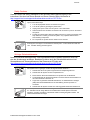
SAFETY STEPS: Whenever you remove the chassis covers to access the inside of the
system, follow these steps:
1.
Turn off all peripheral devices connected to the system.
2.
Turn off the system by pressing the power button.
3.
Unplug all AC power cords from the system or from wall outlets.
4.
Label and disconnect all cables connected to I/O connectors or ports on the back of
the system.
5.
Provide some electrostatic discharge (ESD) protection by wearing an antistatic wrist
strap attached to chassis ground of the system—any unpainted metal surface—
when handling components.
6.
Do not operate the system with the chassis covers removed.
A microprocessor and heat sink may be hot if the system has been running. Also, there may
be sharp pins and edges on some board and chassis parts. Contact should be made with
care. Consider wearing protective gloves.
Wichtige Sicherheitshinweise
Lesen Sie zunächst sämtliche Warn- und Sicherheitshinweise in diesem Dokument, bevor Sie
eine der Anweisungen ausführen. Beachten Sie hierzu auch die Sicherheitshinweise zu IntelServerplatinen und -Servergehäusen auf der Ressourcen-CD oder unter
http://support.intel.com/support/motherboards/server/sb/cs-010770.htm.
SICHERHEISMASSNAHMEN: Immer wenn Sie die Gehäuseabdeckung abnehmen um an
das Systeminnere zu gelangen, sollten Sie folgende Schritte beachten:
1.
Schalten Sie alle an Ihr System angeschlossenen Peripheriegeräte aus.
2.
Schalten Sie das System mit dem Hauptschalter aus.
3.
Ziehen Sie den Stromanschlußstecker Ihres Systems aus der Steckdose.
4.
Auf der Rückseite des Systems beschriften und ziehen Sie alle Anschlußkabel von
den I/O Anschlüssen oder Ports ab.
5.
Tragen Sie ein geerdetes Antistatik Gelenkband, um elektrostatische Ladungen
(ESD) über blanke Metallstellen bei der Handhabung der Komponenten zu
vermeiden.
6.
Schalten Sie das System niemals ohne ordnungsgemäß montiertes Gehäuse ein.
Der Mikroprozessor und der Kühler sind möglicherweise erhitzt, wenn das System in Betrieb
ist. Außerdem können einige Platinen und Gehäuseteile scharfe Spitzen und Kanten
aufweisen. Arbeiten an Platinen und Gehäuse sollten vorsichtig ausgeführt werden. Sie
sollten Schutzhandschuhe tragen.
Intel® Remote Management Module 2 User Guide
v
Contents
重要安全指导
在执行任何指令之前,请阅读本文档中的所有注意事项及安全声明。参见 Resource
CD(资源光盘) 和/或http://support.intel.com/support/motherboards/server/sb/cs-010770.htm
上的 Intel Server Boards and Server Chassis Safety Information(《Intel
服务器主板与服务器机箱安全信息》)。
Consignes de sécurité
Lisez attention toutes les consignes de sécurité et les mises en garde indiquées dans ce
document avant de suivre toute instruction. Consultez Intel Server Boards and Server Chassis
Safety Information sur le CD Resource CD ou bien rendez-vous sur le site
http://support.intel.com/support/motherboards/server/sb/cs-010770.htm.
CONSIGNES DE SÉCURITÉ -Lorsque vous ouvrez le boîtier pour accéder à l’intérieur du
système, suivez les consignes suivantes:
1.
Mettez hors tension tous les périphériques connectés au système.
2.
Mettez le système hors tension en mettant l’interrupteur général en position OFF
(bouton-poussoir).
3.
Débranchez tous les cordons d’alimentation c.a. du système et des prises murales.
4.
Identifiez et débranchez tous les câbles reliés aux connecteurs d’E-S ou aux accès
derrière le système.
5.
Pour prévenir les décharges électrostatiques lorsque vous touchez aux
composants, portez une bande antistatique pour poignet et reliez-la à la masse du
système (toute surface métallique non peinte du boîtier).
6.
Ne faites pas fonctionner le système tandis que le boîtier est ouvert.
Le microprocesseur et le dissipateur de chaleur peuvent être chauds si le système a été
sous tension. Faites également attention aux broches aiguës des cartes et aux bords
tranchants du capot. Nous vous recommandons l'usage de gants de protection.
Instrucciones de seguridad importantes
Lea todas las declaraciones de seguridad y precaución de este documento antes de realizar
cualquiera de las instrucciones. Vea Intel Server Boards and Server Chassis Safety Information
en el CD Resource y/o en http://support.intel.com/support/motherboards/server/sb/cs010770.htm.
INSTRUCCIONES DE SEGURIDAD: Cuando extraiga la tapa del chasis para acceder al
interior del sistema, siga las siguientes instrucciones:
vi
1.
Apague todos los dispositivos periféricos conectados al sistema.
2.
Apague el sistema presionando el interruptor encendido/apagado.
3.
Desconecte todos los cables de alimentación CA del sistema o de las tomas de
corriente alterna.
4.
Identifique y desconecte todos los cables enchufados a los conectores E/S o a los
puertos situados en la parte posterior del sistema.
5.
Cuando manipule los componentes, es importante protegerse contra la descarga
Contents
electrostática (ESD). Puede hacerlo si utiliza una muñequera antiestática sujetada a la
toma de tierra del chasis — o a cualquier tipo de superficie de metal sin pintar.
6.
No ponga en marcha el sistema si se han extraído las tapas del chasis.
Si el sistema ha estado en funcionamiento, el microprocesador y el disipador de calor
pueden estar aún calientes. También conviene tener en cuenta que en el chasis o en el
tablero puede haber piezas cortantes o punzantes. Por ello, se recomienda precaución y el
uso de guantes protectores.
AVVERTENZA: Italiano
PASSI DI SICUREZZA: Qualora si rimuovano le coperture del telaio per accedere
all’interno del sistema, seguire i seguenti passi:
1
Spegnere tutti i dispositivi periferici collegati al sistema.
2
Spegnere il sistema, usando il pulsante spento/acceso dell’interruttore del
sistema.
3
Togliere tutte le spine dei cavi del sistema dalle prese elettriche.
4
Identificare e sconnettere tutti i cavi attaccati ai collegamenti I/O od alle prese
installate sul retro del sistema.
5
Qualora si tocchino i componenti, proteggersi dallo scarico elettrostatico
(SES), portando un cinghia anti-statica da polso che è attaccata alla presa a
terra del telaio del sistema – qualsiasi superficie non dipinta – .
6
Non far operare il sistema quando il telaio è senza le coperture.
Se il sistema è stato a lungo in funzione, il microprocessore e il dissipatore di calore
potrebbero essere surriscaldati. Fare attenzione alla presenza di piedini appuntiti e parti
taglienti sulle schede e sul telaio. È consigliabile l'uso di guanti di protezione.
Intel® Remote Management Module 2 User Guide
vii
Contents
About this Manual ......................................................................................................................iii
Manual Organization..................................................................................................................iii
Safety Information..................................................................................................................... iv
1.
Intel® Remote Management Module 2 Features................................................................. 6
1.1
Feature Summary .................................................................................................... 7
1.1.1
1.2
2.
Supported Operating Systems................................................................................. 7
1.2.1
Server System ......................................................................................................... 7
1.2.2
Client System........................................................................................................... 8
Hardware Installations and Initial Configuration............................................................... 9
2.1
Before You Begin..................................................................................................... 9
2.2
Tools and Supplies Needed..................................................................................... 9
2.3
Installation................................................................................................................ 9
2.3.1
Installation on Intel® Server Board S5000XAL / S5000PAL................................... 10
2.3.2
Installation on the Intel® Server Board S5000PSL................................................. 11
2.3.3
Installation on Intel® Server System S7000FC4UR ............................................... 12
2.4
3.
4.
Feature Details ........................................................................................................ 7
Initial Network Configuration.................................................................................. 14
®
Intel RMM2 Configuration Utility - Psetup ...................................................................... 15
3.1
Psetup Outline ....................................................................................................... 15
3.2
Using the Psetup Tool via Graphical User Interface.............................................. 15
3.3
Mac Address Detection.......................................................................................... 16
3.3.1
Using the Psetup Utility for Windows* ................................................................... 16
3.3.2
Using the Psetup Utility for Linux........................................................................... 17
3.4
Authentication ........................................................................................................ 17
3.5
Operating the Psetup Utility from a Linux Command Line ..................................... 17
Intel® RMM2 Configuration Utility - KiraTool .................................................................. 19
4.1
KiraTool Outline ..................................................................................................... 19
4.1.1
About the KiraTool Software.................................................................................. 19
4.1.2
KiraTool Syntax ..................................................................................................... 19
4.1.3
KiraTool Options for the Connection Type............................................................. 20
Intel® Remote Management Module 2 User Guide
iii
Contents
4.1.4
KiraTool Options for the Authentication Type ........................................................ 20
4.1.5
KiraTool Options for Other Purposes..................................................................... 21
4.1.6
KiraTool Commands .............................................................................................. 21
4.2
4.2.1
General Commands............................................................................................... 22
4.2.2
User Administration ............................................................................................... 24
4.2.3
Network Interface Commands ............................................................................... 24
4.2.4
Firmware Commands ............................................................................................ 27
4.2.5
Test Commands .................................................................................................... 28
4.2.6
Test Types ............................................................................................................. 29
4.2.7
Test Return Codes................................................................................................. 30
4.3
6.
iv
KiraTool Commands in Detail ................................................................................ 31
4.3.1
Windows* Version.................................................................................................. 31
4.3.2
EFI Version ............................................................................................................ 35
4.3.3
DOS* Version ........................................................................................................ 35
4.3.4
Linux Version ......................................................................................................... 36
4.4
5.
KiraTool Commands in Detail ................................................................................ 22
Uninstalling KiraTool.............................................................................................. 37
4.4.1
Windows Version Uninstallation ............................................................................ 37
4.4.2
Linux Version Uninstallation .................................................................................. 38
4.4.3
DOS and EFI Version Uninstallation...................................................................... 38
Getting Started with Intel® RMM2 Operation.................................................................... 39
5.1
Logging in for the First Time .................................................................................. 39
5.2
Prerequisites.......................................................................................................... 39
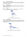
5.3
Browsers................................................................................................................ 40
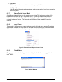
5.4
Navigation.............................................................................................................. 40
5.5
Online Help ............................................................................................................ 41
5.6
Logging out of the Intel® RMM2 ............................................................................. 42
Remote Console (KVM) Operation.................................................................................... 43
6.1
General Description ............................................................................................... 43
6.2
Main Window ......................................................................................................... 43
6.3
Remote Console Control Bar................................................................................. 44
6.4
Remote Console Options Menu............................................................................. 46
6.4.1
Monitor Only .......................................................................................................... 46
6.4.2
Exclusive Access ................................................................................................... 46
Contents
6.4.3
Screenshot to Clipboard ........................................................................................ 47
6.4.4
Readability Filter .................................................................................................... 47
6.4.5
Scaling ................................................................................................................... 47
6.4.6
Mouse Handling..................................................................................................... 47
6.4.7
Single/Double Mouse Mode................................................................................... 48
6.4.8
Local Cursor .......................................................................................................... 48
6.4.9
Chat Window ......................................................................................................... 48
6.4.10
Soft Keyboard ........................................................................................................ 49
6.4.11
Local Keyboard...................................................................................................... 50
6.4.12
Hotkeys.................................................................................................................. 50
6.4.13
Encoding................................................................................................................ 51
6.5
6.5.1
6.6
7.
Remote Console Status Line ................................................................................. 52
Visual Display of Access Setting ........................................................................... 53
Recommended Mouse Settings............................................................................. 53
6.6.1
Microsoft Windows* 2000, 2003, XP (All Versions) ............................................... 53
6.6.2
Linux ...................................................................................................................... 53
Menu Options of the Intel® RMM2 Embedded Web ......................................................... 54
7.1
Remote Control...................................................................................................... 54
7.1.1
KVM Console......................................................................................................... 54
7.1.2
Remote Power ....................................................................................................... 55
7.2
Virtual Media.......................................................................................................... 56
7.2.1
Floppy Disk Image ................................................................................................. 56
7.2.2
Drive Redirection ................................................................................................... 56
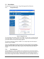
7.3
System Health ....................................................................................................... 57
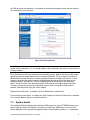
7.3.1
System Information................................................................................................ 58
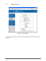
7.3.2
Chassis Control ..................................................................................................... 59
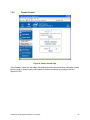
7.3.3
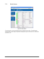
Monitor Sensors..................................................................................................... 60
7.3.4
System Hardware Event Log ................................................................................. 61
7.4
User Management ................................................................................................. 61
7.4.1
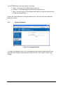
Change Password ................................................................................................. 62
7.4.2
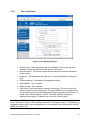
User and Groups ................................................................................................... 63
7.4.3
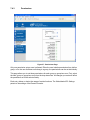
Permissions ........................................................................................................... 64
7.5
7.5.1
KVM Settings ......................................................................................................... 65
User Console ......................................................................................................... 65
Intel® Remote Management Module 2 User Guide
v
Contents
7.5.2
7.6
Keyboard/Mouse.................................................................................................... 68
Device Setting........................................................................................................ 69
7.6.1
Network.................................................................................................................. 69
7.6.2
Dynamic DNS ........................................................................................................ 72
7.6.3
Security.................................................................................................................. 74
7.6.4
Certificate............................................................................................................... 79
7.6.5
USB ....................................................................................................................... 82
7.6.6
IPMI ....................................................................................................................... 83
7.6.7
Date and Time ....................................................................................................... 84
7.6.8
Authentication Settings .......................................................................................... 85
7.6.9
SMTP Settings....................................................................................................... 87
7.6.10
Event Log............................................................................................................... 88
7.6.11
SNMP .................................................................................................................... 90
7.7
Maintenance .......................................................................................................... 92
7.7.1
Device Information................................................................................................. 92
7.7.2
Event Log............................................................................................................... 93
7.7.3
Update Firmware ................................................................................................... 94
7.7.4
Unit Reset .............................................................................................................. 95
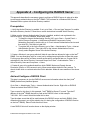
Appendix A - Configuring the RADIUS Server....................................................................... 97
Prerequisites............................................................................................................................ 97
Add and Configure a RADIUS Client ....................................................................................... 97
Setup a Custom Remote Access Policy .................................................................................. 98
Appendix B – System Management Architecture for Server Hardware – Command Line
Protocol ..................................................................................................................................... 99
Command Line Protocol .......................................................................................................... 99
CLP to CIM mapping ............................................................................................................... 99
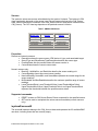
Global commands h ........................................................................................................... 100
Admin domain / .................................................................................................................. 100
/system# 100
/system1/locator1 ............................................................................................................... 100
Sensors 101
Properties: .......................................................................................................................... 101
Supported commands: ....................................................................................................... 101
/system2/account#................................................................................................................. 101
vi
Contents
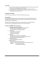
Properties: .......................................................................................................................... 102
Supported commands: ....................................................................................................... 102
Associations: ...................................................................................................................... 102
Examples of SMASH CLP Commands .............................................................................. 102
Appendix C. KiraTool Commands ......................................................................................... 103
Supported Operating Systems............................................................................................... 103
Supported Interfaces ............................................................................................................. 103
Supported Functionality ......................................................................................................... 103
Usage
103
Return Codes......................................................................................................................... 107
Appendix D. Key Codes ......................................................................................................... 109
Intel® Remote Management Module 2 User Guide
vii
Figures
Figure 1: Intel® Remote Management Module 2 and Network Interface Card ............................. 6
Figure 2: Installing the Intel® RMM2............................................................................................ 10
Figure 3: Installing the Intel® RMM2 Dedicated NIC Module ...................................................... 11
Figure 4: Installing the Intel® RMM2............................................................................................ 12
Figure 5: Installing the Intel® RMM2 Dedicated NIC Module ...................................................... 12
Figure 6: Attaching the EMI Gasket on the Intel® Server System S7000FC4UR I/O Riser Board13
Figure 7: Installing the Intel® RMM2 Dedicated NIC Module ...................................................... 13
Figure 8: Installing the Intel® RMM2............................................................................................ 14
Figure 9: Psetup Utility (Windows* Version) ............................................................................... 15
Figure 10: Psetup Tool (Linux Version) ...................................................................................... 16
Figure 11: KiraTool Setup Welcome Screen............................................................................... 31
Figure 12: KiraTool Setup “Choose Components” Screen ......................................................... 32
Figure 13: KiraTool Setup Install Location Screen...................................................................... 32
Figure 14: KiraTool Setup Installing Screen ............................................................................... 33
Figure 15: KiraTool Setup Finished Screen ................................................................................ 33
Figure 16: Start the KiraTool under Microsoft Windows XP* ...................................................... 34
Figure 17: Starting the KiraTool under Microsoft Windows XP* ................................................. 34
Figure 18: Working with KiraTool under EFI ............................................................................... 35
Figure 19: Working with KiraTool under DOS* ........................................................................... 35
Figure 20: Working with KiraTool under Linux ............................................................................ 36
Figure 21: Uninstall the KiraTool under Windows* ..................................................................... 37
Figure 22: KiraTool Uninstall Wizard .......................................................................................... 37
Figure 23: Finished KiraTool Uninstall Wizard........................................................................... 38
Figure 24: Login screen ............................................................................................................. 39
Figure 25: Encryption Key Length Displayed by Internet Explorer ............................................. 40
Figure 26: Home Page when Accessing the Intel® RMM2.......................................................... 41
Figure 27: Web Interface – Top Screen Buttons......................................................................... 41
Figure 28: Launching the Online Help ........................................................................................ 42
Figure 29: Remote Console ........................................................................................................ 43
Figure 30: Remote Console Control Bar..................................................................................... 44
Figure 31: Remote Console Applet Drive Redirection Menu ...................................................... 44
Intel® Remote Management Module 2 User Guide
iii
Figures
Figure 32: Redirecting a Local Drive........................................................................................... 45
Figure 33: Redirecting an ISO Image ......................................................................................... 45
Figure 34: Remote Console Options Menu................................................................................ 46
Figure 35: Remote Console Options Menu: Scaling................................................................... 47
Figure 36: Remote Console Options Menu: Mouse Handling..................................................... 47
Figure 37: Remote Console Options Menu: Cursor.................................................................... 48
Figure 38: Chat Window ............................................................................................................. 48
Figure 39: Soft Keyboard ............................................................................................................ 49
Figure 40: Soft Keyboard Mapping ............................................................................................. 50
Figure 41: Local Keyboard Language Menu............................................................................... 50
Figure 42: Remote Console Confirmation Dialog ....................................................................... 51
Figure 43: Remote Console Options: Encoding Compression ................................................... 51
Figure 44: Remote Console Options: Predefined Encoding Compression ................................. 52
Figure 45: Remote Console Options: Color Depth ..................................................................... 52
Figure 46: Status Line................................................................................................................. 53
Figure 47: Remote Console Menu .............................................................................................. 54
Figure 48: Remote Power Display .............................................................................................. 55
Figure 49: Floppy Disk Image ..................................................................................................... 56
Figure 50: Drive Redirection ....................................................................................................... 57
Figure 51: System Information.................................................................................................... 58
Figure 52: Chassis Control Page ................................................................................................ 59
Figure 53: Sensor Status ............................................................................................................ 60
Figure 54: System Hardware Event Log ..................................................................................... 61
Figure 55: Changing Passwords................................................................................................. 62
Figure 56: User Management Page............................................................................................ 63
Figure 57: Permissions Page...................................................................................................... 64
Figure 58: Remote Console Setting for Users ............................................................................ 65
Figure 59: User Console Setting, Part 2 ..................................................................................... 66
Figure 60: Keyboard / Mouse Configuration ............................................................................... 68
Figure 61: Network Menu............................................................................................................ 69
Figure 62: Dynamic DNS Menu .................................................................................................. 72
Figure 63: Dynamic DNS Scenario ............................................................................................. 72
Figure 64: Security Menu............................................................................................................ 74
Figure 65: Example of IP Access Control ................................................................................... 76
iv
Figures
Figure 66: Example of Group Based System Access Control .................................................... 77
Figure 67: Certificate Menu......................................................................................................... 79
Figure 68: Certificate Upload ...................................................................................................... 80
Figure 69: USB Settings ............................................................................................................. 82
Figure 70: IPMI Settings ............................................................................................................. 83
Figure 71: Date and Time Menu ................................................................................................. 84
Figure 72: LDAP and Other Authentication Settings................................................................... 85
Figure 73: SMTP Settings Menu................................................................................................. 87
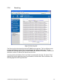
Figure 74: Event log Menu – Upper Screen Display................................................................... 88
Figure 75: Event Log Menu – Lower Display Screen.................................................................. 89
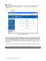
Figure 76: SMTP Menu............................................................................................................... 90
Figure 77: Device Information Page ........................................................................................... 92
Figure 78: Connected Users ....................................................................................................... 92
Figure 79: Event Log List ............................................................................................................ 93
Figure 80: Firmware Update Page.............................................................................................. 94
Figure 81: Unit Reset Page......................................................................................................... 95
Figure 82. English (US) Keyboard Layout, Used for the Key Codes ........................................ 109
Intel® Remote Management Module 2 User Guide
v
1.
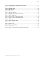
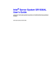
Intel® Remote Management Module 2 Features
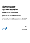
This chapter briefly describes the main features of Intel® Remote Management Module 2 (Intel®
RMM2). This chapter provides a photograph of the product and a list of module features.
The Intel® Remote Management Module 2 is shown in the following photo.
Figure 1: Intel® Remote Management Module 2 and Network Interface Card
Intel® Remote Management Module 2 User Guide
6
1.1
Feature Summary
The Intel® RMM2 works as an integrated solution on your server system. Based on an
embedded operating system, the Intel® RMM2 add-on card provides both exceptional stability
and permanent availability independent of the present state of the server’s operating system.
As a system administrator, you can use the Intel® RMM2 to gain location-independent remote
access to respond to critical incidents and to undertake necessary maintenance.
1.1.1
Feature Details
®
The Intel RMM2 add-on card defines a new class of remote access devices. It offers
convenient, remote KVM access and control via LAN or Internet. It captures, digitizes, and
compresses video and transmits it with keyboard and mouse signals to and from a remote
computer. Remote access and control software runs on Intel® RMM2 embedded processors so
there is no impact to the server operation or network performance. In addition, the Intel® RMM2
add-on card offers integrated remote power management using IPMI. Key features of the Intel®
RMM2 add-on card are:
•
•
•
•
•
•
•
•
•
•
•
•
•
1.2
Embedded Web UI - Remote Power on\off, system health, system info, Intel®
RMM2 Firmware Update, Event log includes Intel® RMM2 events
KVM redirection via Dedicated NIC– high performance, multiple concurrent
sessions
USB 2.0 media redirection - boot over remote media
Security – SSL, LDAP, SSH, RADIUS support
OEM Customization
Email Alerting for Intel® RMM2 events
SMASH CLI/CLP, WS- MAN , SNMP traps for Intel® RMM2 events
Soft Keyboard via KVM (multiple language support)
IPMI V2.0 Compliance
Intel® RMM2 dedicated NIC can works as BMC channel 3 (IPMI forwarding)
Automatically senses video resolution for best possible screen capture
High-performance mouse tracking and synchronization
Allows remote viewing and configuration in pre-boot POST and BIOS setup
Supported Operating Systems
The Intel® RMM2 runs independently of the host operating system on the server where it is
installed except during remote console (KVM) connections. During remote console connections
the keyboard, mouse, and video of the console system operate just as if you were at the server
where the Intel® RMM2 is connected. During remote console connections the interaction with
the host operating system limits the support to operating systems that have been validated.
Those operating systems are listed below:
1.2.1
Server System
The following operating systems are supported on the managed server:
• Microsoft Windows 2003 Server* with Service Pack 1 or later, and all recent
updates
• Red Hat* Enterprise Linux Advanced Server 4
Intel® Remote Management Module 2 User Guide
7
1.2.2
Client System
The following client operating system and Internet browser combinations have been tested:
• Red Hat* Linux 4 / Red Hat* Linux 4 ES with Firefox
• SuSE* 9 Pro 9.1 with Mozilla
• Microsoft Windows XP Pro* with Service Pack 2, with Internet Explorer
• Microsoft Windows 2003 ES* with Service Pack 1, with Internet Explorer
8
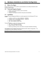
2.
Hardware Installations and Initial Configuration
2.1
Before You Begin
Before working with your server product, pay close attention to the Safety Information at the
beginning of this manual.
2.2
Tools and Supplies Needed
•
•
•
2.3
Phillips* (cross head) screwdriver (#1 bit and #2 bit)
Needle nosed pliers
Antistatic wrist strap and conductive foam pad (recommended)
Installation
The Intel® Remote Management Module is currently supported on the following Intel® server
boards:
• All SKUs of Intel® Server Board S5000XAL / S5000PAL
• All SKUs of Intel® Server Board S5000XSL / S5000PSL
• Intel® Server System SC5400RA
• Intel® Server System S7000FC4UR
The Intel® RMM2 box contains the following components:
• Intel® Remote Management Module
• Network Interface Card (NIC) module
• Plastic bag containing screws, slot bracket, three plastic standoffs and cabling
The installation will vary between these server boards and their chassis configurations. The
following sections detail installation instructions.
Note: Remove AC power from the server before installing the Intel® RMM2.
Intel® Remote Management Module 2 User Guide
9
Installation on Intel® Server Board S5000XAL / S5000PAL
2.3.1
The Intel® Server Board S5000XAL / S5000PAL installs in rack mount 1U or 2U chassis. The
same installation steps apply to both chassis types.
•
•
•
•
•
•
•
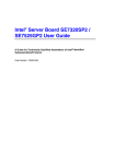
The Intel® RMM2 module ships with one plastic standoff pre-installed as shown in
Figure 2. The standoff will align with a hole in the server baseboard when mounted to
the baseboard.
Attach the Intel® RMM2 to the connector on the server baseboard labeled “RMM”.
Snap the standoff into the corresponding hole in the baseboard.
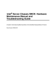
Next, insert three plastic standoffs into the holes of the Intel® RMM2 NIC module. See
Figure 3.
Push out and remove the metal cover on the chassis where the NIC RJ-45 receptacle
will align.
Mount the NIC module to the header on the baseboard and snap the three standoffs
into the corresponding holes in the baseboard. This will align the RJ-45 with the
opening in the chassis.
Make a note of the MAC address of the Intel® RMM2. It is written on a label attached
to the module (not the NIC). Keeping a record now may eliminate the need to reopen
the cover later.
Replace the chassis cover, attach AC power and connect a network cable to the Intel®
RMM2 NIC.
AF002058
Figure 2: Installing the Intel® RMM2
10
AF002057
Figure 3: Installing the Intel® RMM2 Dedicated NIC Module
Installation on the Intel® Server Board S5000PSL
2.3.2
The Intel® Server Board S5000PSL installs in pedestal style chassis. The following steps detail
the installation for this type of chassis.
•
•
•
•
•
•
•
The Intel® RMM2 module ships with one plastic standoff pre-installed as shown in
Figure 4. The standoff will align with a hole in the server baseboard when mounted
to the baseboard.
Attach the Intel® RMM2 to the connector on the server baseboard labeled “RMM”.
Snap the standoff into the corresponding hole in the baseboard.
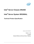
Attached the NIC module to the add-in card slot bracket as shown in Figure 5. Use
the screws provided.
Mount the bracket with the NIC module in a chassis slot near the baseboard
connector for the cable.
Attach the cable from the baseboard to the NIC module as shown.
Make a note of the MAC address of the Intel® RMM2. It is written on a label attached
to the module (not the NIC). Keeping a record now may eliminate the need to
reopen the cover later.
Replace the chassis cover, attach AC power and connect a network cable to the
Intel® RMM2 NIC.
Intel® Remote Management Module 2 User Guide
11
AF002055
Figure 4: Installing the Intel® RMM2
AF002056
Figure 5: Installing the Intel® RMM2 Dedicated NIC Module
Installation on Intel® Server System S7000FC4UR
2.3.3
The following steps detail the installation of Intel® RMM2 on the Intel® Server System
S700FC4UR.
•
•
•
•
12
Remove the top cover of the Intel® Server System S7000FC4UR. For instructions,
see the Intel® Server System S7000FC4UR product guide.
Remove the I/O riser card. For instructions, see the Intel® Server System
S7000FC4UR product guide.
Set the I/O riser card on a static-controlled surface with the components facing up.
Write down the MAC address on the Intel® RMM2. It is on a label attached to the
Intel® RMM2. If you do not write down the MAC address before installing the Intel®
RMM2, you will need to open the system later to record this information before you
can configure the Intel® RMM2.
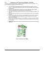
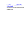
The I/O gasket is required to meet EMI requirements.
•
•
Peel the backing from the EMI gasket that is included with your Intel® Remote
Management Module 2 kit. See letter “A” in the following figure.
Adhere the EMI gasket to the I/O riser board where the NIC will contact the I/O riser. See
letter “B” in the figure.
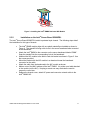
Figure 6: Attaching the EMI Gasket on the Intel® Server System S7000FC4UR I/O Riser Board
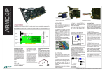
•
Screw the NIC module to the J2B1 header on the I/O riser board, using the provided
screws. This aligns the RJ-45 port with the opening on the back cover of the I/O riser
board. See the following figure.
Figure 7: Installing the Intel® RMM2 Dedicated NIC Module
Intel® Remote Management Module 2 User Guide
13
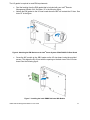
•
•
Align the connector on the Intel® RMM2 to the J6C1 connector on the I/O riser board and
align the plastic standoff to the Intel® RMM2 corresponding hole in the I/O riser board.
Push down on the Intel® RMM2 to attach it to the I/O riser board.
Figure 8: Installing the Intel® RMM2
2.4
Initial Network Configuration
When first powered on, the Intel® RMM2 will use a DHCP server acquire an assigned network IP
address. If no DHCP server is available, the Intel® RMM2 will need to be configured to use a
static IP address. A utility named psetup is provided to assist with discovery and IP address
configuration, and also to view the IP address that was assigned by a DHCP server. Psetup is
available in Linux and Windows* versions. See Section 3 for additional details on psetup.
14
3.
Intel® RMM2 Configuration Utility - Psetup
3.1
Psetup Outline
The psetup utility is a graphical user interface application, which is used to determine the IP
address assigned to the Intel® RMM2 by the DHCP server, or to change the device’s initial
network configuration. It allows access to the Intel® RMM2 even if it has no IP address configured.
Psetup can access the Intel® RMM2 by two ways:
•
•
3.2
Locally:
Psetup can be started directly on the host containing the Intel® RMM2. The tool
uses SCSI/USB driver to access the module.
Remotely:
Psetup can be started on any host connected to the same subnet (broadcast
domain) as the Intel® RMM2. Psetup uses UDP broadcasts to access the module.
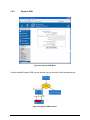
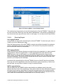
Using the Psetup Tool via Graphical User Interface
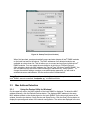
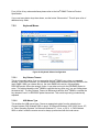
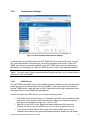
A typical Windows* version of the psetup screen is shown in Figure 9.
Figure 9: Psetup Utility (Windows* Version)
Intel® Remote Management Module 2 User Guide
15
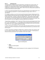
Figure 10: Psetup Tool (Linux Version)
When first launched, psetup automatically scans and auto-detects all Intel® RMM2 modules
on the local host and on the subnet. The MAC addresses of all detected modules are
available as a drop down list. This list allows you to connect and configure individual Intel®
RMM2 modules. You can restart the auto-detection by clicking on "Refresh Devices".
After selecting a device by MAC address, the "Device Type" will show "Intel(R) RMM2". You
are now able to query the current network settings of that device by "Query Device". To
change the network settings or assign a new administrator password, you will need to
authenticate as an administrator. See the section called “Authentication”.
Note: The Linux version of psetup needs module “sg” running on the system to detect a local
Intel® RMM2; execute command “ modprobe sg ” to load this module.
3.3
3.3.1
Mac Address Detection
Using the Psetup Utility for Windows*
On the upper left corner, the MAC address of the Intel® RMM2 is displayed. To detect the MAC
address manually, click the Refresh Devices button. The displayed MAC address is the same
MAC address printed on the sticker placed on the Intel® RMM2. On the lower right corner of the
window, there are two buttons: Query Device and Setup Device. Click the Query Device button to
display the preconfigured values of the network configuration. The values are displayed in the text
16
fields located above. If necessary, adjust the network settings. To save the changes, enter a user
name and a password, then click the Setup Device button.
3.3.2
Using the Psetup Utility for Linux
On the top of the window, the MAC address of the device is displayed. To detect the MAC
address manually, click the button Refresh. The displayed MAC address is the same MAC
address printed on the white sticker placed on the back of the Intel® RMM2. Furthermore, there
are two buttons on the window: Query Device and Setup Device. Press the Query Device button
to display the preconfigured values of the network configuration. The values are displayed in the
text fields located nearby. If necessary, adjust the network settings. To save the changes, enter a
user name and a password, then click the Setup Device button.
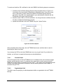
3.4
Authentication
The “Authentication” portion of psetup allows you to change the super user/administrator
password. To modify the current authentication settings, enter your login as super
user/administrator and change your password.
•
•
•
•
Super user login:
Enter the login name of the super user. The initial value is "admin".
Super user password:
Enter the current password for the super user. This initial value is "password".
New super user password:
Enter the new password for the super user.
New password (confirm):
Re-type the new password for the super user.
To close the window and accept the changes, click the OK button; otherwise click the Cancel
button (on Windows*). On a Linux system close the window by clicking the appropriate window
button.
3.5
Operating the Psetup Utility from a Linux Command Line
It is also possible to operate psetup from a Linux command line. The following list shows the
command syntax and their usage. Example commands are shown at the end of the section.
--mac <MAC address of the device>
Shows the current network configuration.
--ip <new IP address>
Set a new IP address.
--ipacp <dhcp|bootp|none>
Set the auto configuration.
--netmask <net mask>
Set a new netmask.
--gateway <gateway address>
Set a new gateway address.
Intel® Remote Management Module 2 User Guide
17
--login <username>
A valid user name with administration rights is required in order to change the network
configuration.
--pw <password>
Password of the specified user.
--pw-new <password>
The specified user gets a new password.
The following examples show commands and their results:
•
Displaying the current network settings:
test@teststation:~# /home/test/psetup --mac 00:0D:5D:00:65:78
IP auto configuration: dhcp
IP address: 192.168.5.135
Subnet mask: 255.255.255.0
Gateway: 192.168.5.1
•
Changing the network settings:
test@teststation:~# /home/test/psetup
--mac 00:0D:5D:00:65:78 --ipacp none --ip 192.168.5.55
--gateway 192.168.5.1 --netmask 255.255.255.0
--login super --pw pass
Device configured successfully.
18
4.
Intel® RMM2 Configuration Utility - KiraTool
4.1
KiraTool Outline
4.1.1
About the KiraTool Software
The KiraTool utility is a command line application which allows the user to manage the Intel®
Remote Management Module 2 (Intel® RMM2). KiraTool can be easily invoked by scripts and
batch files. This allows the user to design script files to configure the Intel® RMM2 quickly and
automatically. KiraTool is available for Windows* and DOS*, EFI and RedHat* Linux.
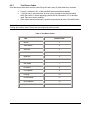
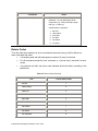
KiraTool can access the Intel® RMM2 via several ways dependent upon the OS that KiraTool is
running. Table1 shows different versions of KiraTool and supported access methods.
Table 1: Accessing the Intel® RMM2
KiraTool Version
4.1.2
Windows*
Linux
EFI
DOS*
Network
9
9
8
8
SCSI/USB driver
9
9
9
8
System Management Interface
8
8
8
9
KiraTool Syntax
KiraTool command syntax contains [option] and [command]. The general syntax is as follows:
kiratool [option] [command]
Single-letter options are preceded with a dash or hyphen such as -s, commands are several
characters long and do not have a preceding hyphen, for example: reset.
For example,
C:\Program Files\KiraTool>kiratool -l 192.168.2.6 -a -u admin p password ip show
IP address: 192.168.2.6
-l, -a, -u and -p are [options], ip show is [command] in this example
Intel® Remote Management Module 2 User Guide
19
4.1.3
KiraTool Options for the Connection Type
Options for connection type are a set of switches which can control how KiraTool accesses the
Intel® RMM2. KiraTool supports following connection options:
•
•
•
-l <IP Address>, use the specified IP address to talk to the Intel® RMM2 over
LAN.
-s, use IPMI over SCSI/USB; this can be augmented with the following -d device
option.
-d, device option: here you can specify the drive identification for SCSI access of
the Intel® RMM2. For the Windows* version use the drive letter, ( e.g. F: ) and for
Linux use /dev/sg1. If you omit this option, KiraTool will attempt to auto-detect the
Intel® RMM2 by probing the SCSI drive identification.
Note: If you do not specify a option for connection type, the default type for the DOS* version is
SMI; the default type for EFI, Linux, and Windows* versions is USB/SCSI.
4.1.4
KiraTool Options for the Authentication Type
In order to execute administrative functions on the Intel® RMM2, KiraTool needs to authenticate
the user; options for authentication are designed for this purpose. All Intel® RMM2 modules come
with a pre-configured administrator login with a factory default password.
Note: The default login is “admin” for the administrator user name and “password” for the
administrator password.
For most KiraTool commands you must specify the administrative login and password to the Intel®
RMM2 using the following options:
-u – the admin user
-p – the admin password
For example:
linux# kiratool -u admin -p password ip show
Note: If you use KiraTool from a batch or script file, you will almost certainly enter these
passwords in clear text in the file. This is a potential security problem: anyone who can read your
command file can attain administrative access to your Intel® RMM2 modules and is able to
reconfigure or disable them; this can have a serious impact on your servers or your network.
MAKE SURE YOU ADEQUATELY PROTECT THESE FILES FROM UNAUTHORIZED ACCESS!
In order to reduce the risk of the clear text passwords in such files, KiraTool offers an option:
-P
prompt for admin password
You would then execute the KiraTool command as follows:
linux# kiratool –u admin –P lan
Password:
20
Note: When you type the password, your characters will not be echoed: they do not appear as
you type.
4.1.5
KiraTool Options for Other Purposes
KiraTool also supports the options below.
•
•
•
•
•
4.1.6
-f, force. This will cause a command to the Intel® RMM2 to be executed without
any user confirmation.
-a, use ASMI mode – needed if you want to access an Intel® RMM2.
-v, verbose. This causes KiraTool to be more informative about the actions taken.
The output (like all outputs of KiraTool) will go the stdout. You can use this option
more than once, and each use increases the level of verbosity.
-c, calm. This option is the same as the –q (quiet) option of other programs:
KiraTool will not generate any output.
-h/-?, KiraTool will print out online help.
KiraTool Commands
The command is a parameter of KiraTool which will request KiraTool to perform different actions
based on the specific command. For example:
C:\Program Files\KiraTool>kiratool -l 192.168.2.6 -a -u admin
-p password ip show
IP address: 192.168.2.6
Intel® Remote Management Module 2 User Guide
21
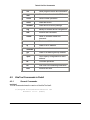
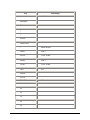
Table 2 KiraTool Commands
4.2
4.2.1
ver
Show program version and information.
info
Show information about the BMC.
serial
Serial number operations.
reset
Reset the device.
defaults
Reset device to factory settings.
cfg
Backup or restore device configuration.
raw
Execute raw commands.
admin
Show or set admin name and
password.
mac
Read or set MAC address.
ip
Read or set IP address.
netmask
Read or set subnet mask.
gw
Read or set default gateway address.
ipsrc
Get or specify configuration for the IP
address.
fw
Firmware operations.
fni
IPMI over FML forwarding commands.
test
Execute self tests.
KiraTool Commands in Detail
General Commands
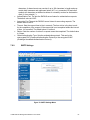
ver(sion)
The ver command shows the version of the KiraTool itself:
C:\Program Files\KiraTool>kiratool ver
KiraTool 1.5.11 (Intel)
22
info(rmation)
The info command shows basic information (manufacturer identification and product ID) of the
Intel® RMM2. The example given also shows the use of the -l, -u and -p options:
C:\Program Files\KiraTool>kiratool -l 192.168.2.6 -a -u admin -p
password info
Manufacturer ID: 10437 (0x28c5)
Product ID:
0 (0x0)
serial [show]
The serial command displays the serial number of the Intel® RMM2. Serial numbers can be strictly
numbers and alpha-numeric strings.
C:\Program Files\KiraTool>kiratool -l 192.168.2.5 –a -u admin
-p password serial
Serial number: 007-BOND
reset
The reset command resets the device.
C:\Program Files\KiraTool>kiratool -l 192.168.2.6 –a -u admin
-p password reset
The device might not respond for about one minute.
Successfully reset the device.
defaults
The defaults command will reset the device to factory defaults.
Note: This operation will also reset the administrative password, so the following KiraTool
command needs to use the default password.
C:\Program Files\KiraTool>kiratool –l 192.168.2.6 –a -u admin
–p password defaults
Successfully reset device to factory settings.
cfg backup <filename>
The cfg backup command will backup the device's configuration to a file.
cfg restore <filename>
The cfg restore command will restore the device's configuration from a file.
Intel® Remote Management Module 2 User Guide
23
raw
The raw command allows you to execute very basic commands on the Intel® RMM2.
These command codes are specific to your Intel® RMM2 and depend heavily on the version. The
example shown here is only an academic example. Normal users of the KiraTool will not need raw
commands.
Important: They are intended for advanced development and debugging use only.
C:\Program Files\KiraTool>kiratool -l 192.168.2.6 –a -u admin
-p password raw 06 01
Executed raw command.
Return code:
0x00
Returned bytes: 0x20 0x01 0x04 0x02 0x02 0x8f 0xc5 0x28
0x00 0x02 0x00 0x00 0x00 0x53 0x59
4.2.2
User Administration
The following commands allow you to manage the administrator account for the Intel® RMM2.
admin [show]
The admin command shows the current setting of the admin account. The show verb is optional.
This is kind of redundant, as you have to know the admin login in order to enquire it.
C:\Program Files\KiraTool>kiratool -l 192.168.2.6 –a -u super
-p password admin
Administrator username: super
admin name
Set the admin users name:
C:\Program Files\KiraTool>kiratool -l 192.168.2.6 –a -u super
-p password admin name admin
Successfully set administrator username to admin
admin password
Set the password for the admin password:
C:\Program Files\KiraTool>kiratool -l 192.168.2.6 –a -u admin
-p pass admin passwd password
Successfully set administrator password.
4.2.3
Network Interface Commands
The following commands allow you to set the parameters for the Intel® RMM2 LAN interface,
including IP address, netmask, gateway, and MAC.
24
Note: When you change these parameters you can very easily make the Intel® RMM2 unavailable
on the network. Changing the MAC or IP address will cause problems with your ARP caching and
the DHCP server accessing information. Normally you should not encounter a need to change
these addresses.
mac [show [-c]]
This command shows the Intel® RMM2’s Ethernet or MAC address:
C:\Program Files\KiraTool>kiratool -l 192.168.2.6 –a -u admin
-p password mac
MAC address: fe:00:00:51:00:38
The optional –c option to this command displays the MAC address in a compact format.
C:\Program Files\KiraTool>kiratool -l 192.168.2.6 –a -u admin
-p password mac show -c
MAC address: FE0000510038
mac set <mac addres>
This command allows you to set the MAC address of the Intel® RMM2. You can also use the
below expanded “:” notation for the MAC address.
C:\Program Files\KiraTool>kiratool -l 192.168.2.6 –a -u admin
-p password mac set FE0000510200
Successfully set MAC address to FE0000510200
or
C:\Program Files\KiraTool>kiratool -l 192.168.2.6 –a -u admin
-p password mac set fe:00:00:51:02:00
Successfully set MAC address to fe:00:00:51:02:00
ip [show]
Shows currently configured IP address:
C:\Program Files\KiraTool>kiratool -l 192.168.2.6 –a -u admin
-p password ip
IP address: 192.168.2.6
ip set <ip address>
This command can assign an IP address for the Intel® RMM2, and set “ipsrc” to “static” as default.
The Intel® RMM2 can get an IP address from the DHCP server or the BIOS of the host. See the
“ipsrc” command for more details.
C:\Program Files\KiraTool>kiratool -l 192.168.2.6 –a -u admin
-p password ip set 192.168.2.5
Successfully set IP address to 192.168.2.5
Intel® Remote Management Module 2 User Guide
25
netmask [show]
Display the netmask currently used by the Intel® RMM2:
C:\Program Files\KiraTool>kiratool -l 192.168.2.6 –a -u admin
-p password netmask
Subnet mask: 255.255.255.0
netmask set <netmask>
You can set the netmask using the normal IP dot notation. Note that changing the netmask can
change the behavior of the Intel® RMM2 with regards to broadcasting. If you “widen” the netmask
then broadcasts by the Intel® RMM2 can use more network bandwidth.
C:\Program Files\KiraTool>kiratool -l 192.168.2.6 –a -u admin
-p password netmask set 255.255.0.0
Successfully set Subnet mask to 255.255.0.0
gw [show]
This shows the currently used default routing gateway for the Intel® RMM2:
C:\Program Files\KiraTool>kiratool -l 192.168.2.6 –a -u admin
-p password gw
Default gateway: 192.168.2.1
gw set <ip address>
This will set a new default routing gateway:
C:\Program Files\KiraTool>kiratool -l 192.168.2.6 –a -u admin
-p password gw set 192.168.2.3
Successfully set Default gateway to 192.168.2.3
ipsrc [show]
This command allows you to view which method the Intel® RMM2 uses in order to get its IP
address:
C:\Program Files\KiraTool>kiratool -l 192.168.2.6 –a -u admin
-p password ipsrc
IP source: DHCP Address
ipsrc set [static|dhcp|bios|none]
The three methods available work as follows:
•
•
•
•
26
dhcp allows the Intel® RMM2 to get the IP configuration from the locally resident
DHCP server. This should be in the same broadcast domain as the Intel® RMM2,
otherwise the DHCP lookup will not work. The DHCP also sets other basic
information like the netmask, IP address, and the gateway address.
static allows only static setting of the Intel® RMM2’s IP address.
none means unspecified.
bios is the method where the Intel® RMM2 will look into the BIOS of the host in order
to find the IP address.
Example:
C:\Program Files\KiraTool>kiratool -l 192.168.2.6 –a -u admin
-p password ipsrc set static
Successfully set IP source to static
4.2.4
Firmware Commands
The KiraTool also allows you to manage the Intel® RMM2’s firmware.
fw [ver]
Shows the version of the firmware.
C:\Program Files\KiraTool>kiratool -l 192.168.2.5 –a -u admin
-p password fw
Firmware version: 4.2.2
Build number:
123
Hardware ID:
0x20
Firmware tag:
Devel
OEM:
intel
fw validate
This command allows you to check if the firmware binary file is compatible with your Intel® RMM2.
It is recommended to check this before you attempt to upgrade the Intel® RMM2’s firmware!
In order to perform the check, you need to know the exact name and location on your hard drive
of the firmware binary.
C:\Program Files\KiraTool>kiratool -l 192.168.2.6 –a -u admin
-p password fw validate
F:\fw-kira-kimasmig4-asmidc-intel_040200-5359.bin
Starting Firmware Validation
Uploading Firmware File
0% ------------------- 50% ------------------ 100%
**************************************************
Upload complete.
Validating Firmware
Firmware file is valid.
Intel® Remote Management Module 2 User Guide
27
fw upgrade
This is the upgrade command corresponding to the above validation. Note that it is quite possible
to “upgrade” the firmware with one of the same version. This is often useful to re-install the
firmware.
C:\Program Files\KiraTool>kiratool -l 192.168.2.6 –a -u admin
-p password fw upgrade
F:\fw-kira- kimasmig4-asmidc-intel_040200-5359.bin
Starting Firmware Upgrade
Uploading Firmware File
0% ------------------- 50% ------------------ 100%
**************************************************
Upload complete.
Flashing Firmware (takes about 1min)
Successfully upgraded firmware.
4.2.5
Test Commands
You can use the test command to perform several self-tests on the Intel® RMM2. You can specify
to test all items or you may skip certain tests.
test <test>
Execute the test labeled “test” on the Intel® RMM2. For example the most basic test is the device
test; it checks to see if the Intel® RMM2 device is responding.
C:\Program Files\KiraTool>kiratool -l 192.168.2.5 –a -u admin
-p password test device
device: ok (firmware 4.2.0, Build 5359)
test all [-s test_to_skip]
This executes all of the tests. It includes the following subtests provided they are available on your
Intel® RMM2, in the following order:
1. device – is the device available
2. ddc info – the DDC interface
3. video status – the status of the video inputs and outputs. May fail if there is no remote
video connected.
4. ipmb bmc – the Board Management Controller (if available)
5. fml esb2 – tests FML interface and the ESB2
6. usb status – the status of the USB interface (for SCSI over USB)
7. nic status – the status of the network interface (LAN)
28
The example below shows you the output of the test all command on an Intel® RMM2 module with
no remote connections:
C:\Program Files\KiraTool>kiratool -l 192.168.2.5 –a -u admin -p
password test all
device: ok (firmware 4.2.0, Build 5359)
Could not query DDC from device: Self test not supported
ddc info: error
video status: failed
IPMB BMC status test failed: Self test not supported
ipmb bmc: error
FML ESB2 status test failed: Self test not supported
fml esb2: error
usb status: failed
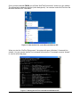
nic status: ok (link: up, duplex: full, speed: 100 MBit)
4.2.6
Test Types
Here is a more detailed listing of the available tests.
Note: the tests are organized in a hierarchical fashion. If you exclude a top-level test like –s nic
from the testing then ALL of the nic tests will be skipped! Conversely if you specify a top-level test
to be done, then all of the available sub-tests will be executed.
•
•
•
•
•
•
•
video <subtest> - tests video interface (digital video input and output)
status – checks detected video signal and resolution
crc – calculate CRC sum over the captured screen
ddc <subtest> – test DDC interface
info – queries EDID information from the device and compares it to the EDID
information known by the OS (only available under Windows)
ipmb <subtest> – test IPMB interface
bmc – test whether a BMC responds over IPMB
evalboard – test whether the IPMB connection between two evaluation boards work
fml <subtest> – test FML interface
esb2 – test whether an ESB2 is responding on FML when TPT (TCP PassThrough)
is active
evalboard – test whether the FML connection between two evaluation boards work
usb <subtest> – test USB interface
status – test whether the device's USB module is enumerated
nic <subtest> – tests network interface
status – test NIC status and parameters
loopback – test NIC loopback functionality
ping <host> – Test whether pinging a host works
Intel® Remote Management Module 2 User Guide
29
4.2.7
Test Return Codes
All of the above tests return an error code if they fail and a zero (0) code when they succeed:
•
•
•
0 (zero) is returned if ALL of the specified tests executed successfully.
-1 (minus one) is returned when an error occurs (except for the test command
itself). Be careful: in some operating systems this is converted to 127 or another
value. Be sure to check carefully!
Other values are returned when a specific test produces an error. See table below.
Note: If the test all command fails, then the returned error code is that of the first failed test.
Testing will continue even if errors are encountered in previous tests.
Table 3: Test Return Codes
Test
30
Return Code
device
1
video status
2
video crc
3
ddc info
4
ipmb ddc
5
fml esb2
6
usb status
7
nic status
8
nic loopback
9
nic ping
10
nic broadcast
11
fml evalboard
12
ipmb evalboard
13
4.3
4.3.1
KiraTool Commands in Detail
Windows* Version
The Windows* version of KiraTool can run on Microsoft Windows 2000*, Microsoft Windows XP*,
and Microsoft Windows 2003 Server*.
Execute a self-extracting executable file: “KiraTool 1.5.xx Intel.EXE”, in the KiraTool package to
install the Windows* version of KiraTool. (xx is revision number)
The welcome page appears; click NEXT to continue.
Figure 11: KiraTool Setup Welcome Screen
Intel® Remote Management Module 2 User Guide
31
The “Choose Components” page allows you to select the components to install. Generally you
should accept the defaults.
Figure 12: KiraTool Setup “Choose Components” Screen
Once you have selected NEXT, the installer will ask you for the location to install the KiraTool.
Generally this will be in the suggested default location of C:\Program Files:
Figure 13: KiraTool Setup Install Location Screen
32
When you accept the suggestion, the installer will proceed to extract and copy the files.
Figure 14: KiraTool Setup Installing Screen
The final installer screen confirms successful installation:
Figure 15: KiraTool Setup Finished Screen
Intel® Remote Management Module 2 User Guide
33
Once you have selected FINISH you will find a “KiraTool Environment” shortcut on your desktop.
The picture below shows the shortcut (in the background). You can also invoke KiraTool from the
Microsoft Windows XP* Start Menu.
Figure 16: Start the KiraTool under Microsoft Windows XP*
When you start the “KiraTool Environment”, the system will open a Windows* Command Line
window. You can execute the KiraTool command at this window. For example, execute “kiratool”
to view its online help page.
.
Figure 17: Starting the KiraTool under Microsoft Windows XP*
34
4.3.2
EFI Version
Follow below steps to execute the KiraTool on the EFI shell.
1. Boot the server to the EFI shell.
2. Copy “KiraTool.efi” from the KiraTool package to a USB key, and plug to the USB port of
the server.
3. Execute “map –r” at the EFI shell to map the USB key; usually it will be mapped with
device “fs0”.
4. Execute “ fs0:” to change current folder to “fs0:\>”.
5. Execute the KiraTool command.
Or you also can copy “KiraTool.efi” to local hard disk to execute it with the same way.
Figure 18: Working with KiraTool under EFI
4.3.3
DOS* Version
To execute the DOS* version of the KiraTool, you need to boot the server to DOS* and directly
execute the KiraTool command as shown below.
Figure 19: Working with KiraTool under DOS*
Intel® Remote Management Module 2 User Guide
35
4.3.4
Linux Version
To execute the Linux version of the KiraTool, you need to copy “ KiraTool-1.5.xx-intel” from the
KiraTool package to a Linux server folder, such as “ /usr/local/bin ”. ( xx is KiraTool revision
number). Follow the process below:
linux# cp kiratool-1.5.11-intel /usr/local/bin
linux# chmod 755 /usr/local/bin/kiratool-1.5.11-intel
KiraTool needs the sg kernel module to detect a locally installed Intel® RMM2. Load this kernel
module before running KiraTool with the command below:
modprobe sg
Figure 20: Working with KiraTool under Linux
36
4.4
4.4.1
Uninstalling KiraTool
Windows Version Uninstallation
The Windows* version of KiraTool contains an uninstall wizard. Refer to Figure 21 to start the
uninstall wizard.
Figure 21: Uninstall the KiraTool under Windows*
Figure 22: KiraTool Uninstall Wizard
Intel® Remote Management Module 2 User Guide
37
After you click the UNISTALL button, the wizard will start the uninstallation process. At the end of
the process, you will see a confirmation screen.
Figure 23: Finished KiraTool Uninstall Wizard
4.4.2
Linux Version Uninstallation
To uninstall the Linux version of KiraTool, you need to remove the files you placed in the system
with command below.
linux# rm /usr/local/bin/kiratool-1.5.11-intel
4.4.3
DOS and EFI Version Uninstallation
Directly remove KiraTool binary file from your disk.
38
Getting Started with Intel® RMM2 Operation
5.
This section describes the operation of the Intel® RMM2. It will cover the initial login to the
advanced features of the module.
5.1
Logging in for the First Time
The Intel® RMM2 add-in card may be accessed using a standard Java enabled web browser. You
may use the HTTP protocol or a secure encrypted connection via HTTPS. Just enter the
configured IP address of the Intel® RMM2 add-in card into your web browser.
http://192.168.1.22/
In order to use a secure connection type in:
https://192.168.1.22/
This will take you to the Intel® RMM2 login page as shown in Figure 24.
Figure 24: Login screen
The initial login settings for the web interface are as follows:
User = admin
Password = password
After the initial login, system administrators and IT professionals may change passwords, create
new users, and have full control over access to the Intel® RMM2. Note that the password is case
sensitive.
5.2
Prerequisites
The Intel® RMM2 features an embedded operating system and applications offering a variety of
standardized interfaces. This section describes the interfaces and how to use them. The
interfaces are accessed using TCP/IP protocol. The following interfaces are supported.
•
HTTP/HTTPS
Full access is provided by the embedded web server. You can access the Intel® RMM2
using the insecure HTTP protocol or using the encrypted HTTPS protocol. Whenever
possible use HTTPS.
Intel® Remote Management Module 2 User Guide
39
•
Telnet
A standard Telnet client can be used to access most of the Intel® RMM2’s functionality,
including a text-mode console redirection. When connected using Telnet, the following
commands are supported: help, quit, version, terminal, and clp.
• SSH
A Secure Shell (SSH) client can also be used to access the Intel® RMM2.
5.3
Browsers
In order to access the remote host system using a securely encrypted connection, you will need a
browser that supports the HTTPS protocol. Strong security is only assured by using a key length
of 128 Bit. Some older browsers may not have a strong 128 Bit encryption algorithm.
If you are using Windows Internet Explorer*, you can verify strong encryption by opening the
“Help / About” menu to read about the key length that is currently activated. The figure below
shows the dialog box presented by Internet Explorer 6.0.
Figure 25: Encryption Key Length Displayed by Internet Explorer
In order to use the Remote Console (KVM) window of your managed server, Java Runtime
Environment (JRE) version 1.4 or higher must be installed. If the browser has no Java support
(such as on a small handheld device), you are still able to maintain your remote host system
using the administration forms displayed by the browser itself.
5.4
Navigation
After the successful login to the Intel® RMM2, the main page of the Intel® RMM2 appears (see
Figure 26). This web page consists of three parts; each of them contains specific information. The
buttons on the top allow you to navigate within the home web page, KVM, and logout screens.
See the figure below for details. The lower left frame contains a navigation bar and allows you to
switch between the different sections of the Intel® RMM2. Within the right frame, task-specific
information is displayed that depends on the section you have chosen before.
40
Figure 26: Home Page when Accessing the Intel® RMM2
Return to the main page of the Intel® RMM2.
Open the Intel® RMM2 Remote Console (KVM).
Exit from the Intel® RMM2 front-end.
Figure 27: Web Interface – Top Screen Buttons
5.5
Online Help
The Web front-end comes with online help. To get further information on a certain topic or group
of options, just click the question mark (?) near the group title displayed in the right page and a
new browser with the online help will be opened.
Intel® Remote Management Module 2 User Guide
41
Figure 28: Launching the Online Help
5.6
Logging out of the Intel® RMM2
This link logs out the current user and presents a new login screen. Please note that an automatic
logout will be performed if there is no activity on the web page for half an hour. There is no
timeout associated with the Remote Console (KVM) connection; it will not timeout until closed by
the user.
42
6.
Remote Console (KVM) Operation
6.1
General Description
The Remote Console is the redirected keyboard, video, and mouse of the remote host system
where the Intel® RMM2 is installed.
Figure 29: Remote Console
The Remote Console window is a Java applet that establishes a TCP connection to the Intel®
RMM2. The protocol that is run over this connection is a unique KVM protocol and not HTTP or
HTTPS. This protocol uses port #443. Your local network environment must permit this
connection to be made, i.e. your firewall and, in case you have a private internal network, your
NAT (Network Address Translation) settings have to be configured accordingly.
6.2
Main Window
Starting the Remote Console opens an additional window. It displays the screen content of your
remote server. The Remote Console will behave exactly as if you were located at the remote
server. The responsiveness of the keyboard and mouse may be slightly delayed depending on
the bandwidth and latency of the network between the Intel® RMM2 and Remote Console.
The Remote Console window always tries to show the remote screen with its optimal size. That
means it will adapt its size to the size of the remote screen initially and after the screen resolution
of the remote screen has been changed. However, you can always resize the Remote Console
window in your local system window as usual.
Intel® Remote Management Module 2 User Guide
43
6.3
Remote Console Control Bar
The upper part of the Remote Console window contains a control bar. Using its elements you can
see the status of the Remote Console and influence the local Remote Console settings. A
description for each control follows.
Note: Some of the following control options are visible only when the operating system type,
"Other Operating Systems” has been selected. For details on selecting “Other Operating
Systems” see the section for Keyboard/Mouse under the KVM Settings menu.
Figure 30: Remote Console Control Bar
•
Drive Redirection
Opens the virtual media Drive Redirection menu for the Remote Console.
Figure 31: Remote Console Applet Drive Redirection Menu
44
Using this menu, you can either redirect a local drive (only available under
Windows*):
Figure 32: Redirecting a Local Drive
or redirect an ISO CD/DVD image:
Figure 33: Redirecting an ISO Image
Intel® Remote Management Module 2 User Guide
45
•
Sync Mouse
Choose this option in order to synchronize the local mouse with the remote mouse
cursor. This is necessary when using accelerated mouse settings on the host system.
In general, there is no need to change mouse settings there. This option is available
when “Other Operating Systems” is selected.
•
Ctrl+Alt+Delete
Special button key to send the "Control Alt Delete" key combination to the remote
system (see also the section called “KVM Settings” for defining a new button). This
option is available when “Other Operating Systems” is selected.
•
Single/Double Mouse Mode
Switches between the Single Mouse Mode (where only the remote mouse pointer is
visible) and the Double Mouse Mode (where the remote and local mouse pointers are
visible and need to be synchronized). Single Mouse Mode is only available if using
SUN JVM 1.4 or higher.
To leave the Single Mouse Mode and get your local mouse pointer back, press AltF12.
6.4
Remote Console Options Menu
To open the Options menu click on the "Options" button.
Figure 34: Remote Console Options Menu
6.4.1
Monitor Only
Toggles the Monitor Only filter on or off. If the filter is switched on, no Remote Console interaction
is possible; the remote screen can be viewed only.
6.4.2
Exclusive Access
If a user has the appropriate permission, all other Remote Console’s connections are forced to
close. No other user can open a Remote Console connection until this user disables the exclusive
access or logs off.
46
6.4.3
Screenshot to Clipboard
This button allows you to capture a screenshot of the Remote Console. The Intel® RMM2 will
automatically place it onto the "clipboard". This allows you to easily import the screenshot into
your documents or other programs.
6.4.4
Readability Filter
Toggles the Readability Filter on or off. If the filter is switched on in scaling mode, it will preserve
most of the screen details even if the image is substantially scaled down. This option is only
available with a JVM 1.4 or higher.
6.4.5
Scaling
Allows you to scale down the Remote Console. You can still use both mouse and keyboard,
however the scaling algorithm will not preserve all display details.
Figure 35: Remote Console Options Menu: Scaling
6.4.6
Mouse Handling
The submenu for Mouse Handling offers two options for synchronizing the local and the remote
mouse pointer when using Soft Mouse Mode as explained in the section called “Mouse and
Keyboard Configuration”. This option is available when “Other Operating Systems” is selected as
the operating system type.
Figure 36: Remote Console Options Menu: Mouse Handling
Intel® Remote Management Module 2 User Guide
47
•
Fast Sync
The fast synchronization is used to correct a temporary but fixed skew.
•
Intelligent Sync
Use this option if the fast sync does not work or the mouse settings have been changed on
the host system.
6.4.7
Single/Double Mouse Mode
Single Mouse Mode will show only the remote mouse pointer. The local mouse pointer will be
hidden and the remote one can be controlled directly. To leave this mode it is necessary to
define a mouse hotkey in the Remote Console Settings Panel. Press this key to free the
captured local mouse pointer. This feature is available when “Other Operating System” is
selected.
6.4.8
Local Cursor
There is a list of different cursor shapes to choose from for the local mouse pointer. The selected
shape will be saved for the current user and activated the next time this user opens the Remote
Console. The number of available shapes depends on the Java Virtual Machine.
Figure 37: Remote Console Options Menu: Cursor
6.4.9
Chat Window
This opens a chat window allowing you to interactively "chat" with other users logged into the
Intel® RMM2.
Figure 38: Chat Window
48
6.4.10
Soft Keyboard
The Soft Keyboard simulates an entire keyboard that is connected to the remote system. It is
necessary when your remote system runs with a completely different language and country
mapping to your administration machine. By selecting the appropriate key(s) you can send key
codes and key sequences to the remote system; it acts as if you are working with a keyboard that
is directly connected to the remote system.
In order to open the Soft Keyboard, select the entry "Soft Keyboard" from the Options menu. You
can send single key strokes like “F” as well as combinations of keys such as “Ctrl+C” or
“Alt+Shift+F4”.
For a single key stroke you can click on the key with the wanted character. Single keys such as
regular characters and numbers are sent immediately. Special keys like “Ctrl” and “Shift”, as well
as the function keys F1 through F12 have to be selected twice. The first press sends the signal
"key is pressed"; the second press indicates the signal "key is released" to the remote system.
After the first press, the key will change its color to signal that the according key is pressed. After
the second press, the key will appear as usual and signal that the key was sent.
To send the key combination “Ctrl+C” select the “Ctrl” key first; the key will change its color. Press
the “C” key. The following key (“C” in our example) will be combined with the previously selected
key. Both the “Ctrl” and “C” keys are released and the key combination will be sent to the remote
system. The “Ctrl” key will appear normal (color change).
In order to send the key combination “Ctrl+F5” three steps are required. Select the “Ctrl” key once
and the “F5” key twice. The last press will release both keys and send the key combination to the
remote system.
In order to send the key combination “Alt+Shift+F4” four steps are required. First, select the “Alt”
key once. Second, select the “Shift” key. Finally, choose the “F4” key twice. The last press will
release all the keys and send the key combination to the remote system.
Figure 39: Soft Keyboard
•
Show
Displays the Soft Keyboard.
•
Mapping
Used for choosing the desired language and country mapping of the Soft Keyboard.
Intel® Remote Management Module 2 User Guide
49
Figure 40: Soft Keyboard Mapping
6.4.11
Local Keyboard
This is used to change the language mapping of your browser machine running the Remote
Console Applet. Normally the applet determines the correct value automatically. However,
depending on your particular JVM and your browser settings, this is not always possible. A
typical example is a German localized system that uses a US-English keyboard mapping. In this
case you have to manually change the Local Keyboard setting to the right language.
Figure 41: Local Keyboard Language Menu
6.4.12
Hotkeys
This opens a list of previously defined hotkeys. In order to send a registered command to the
host system, choose the appropriate entry. A confirmation dialog will be displayed before
sending the selected command to the remote host. Choose "OK" to perform the command on
the remote host.
50
Figure 42: Remote Console Confirmation Dialog
6.4.13
Encoding
These options are used to adjust the encoding level in terms of compression and color depth.
They are available unless "Transmission Encoding" is determined automatically.
Compression Level: You may select a value between 1 and 9 for the desired compression
level, with level 1 enabling the fastest compression and level 9 the best compression. The most
suitable compression level should always be seen as a compromise between the network
bandwidth that is available, on your video picture to be transferred, and on the number of
changes between two single video pictures. We recommend using a higher compression level if
the network bandwidth is low. The higher the compression level, the more time is necessary to
pack or unpack the video data on either side of the connection. The compression quality
depends on the video picture itself, e.g. the number of the colors or the diversity of pixels. The
lower the compression quality, the more data has to be sent and the longer it may take to
transfer the whole video picture. If level 0 is chosen, the video compression is disabled
completely.
Figure 43: Remote Console Options: Encoding Compression
Predefined & Lossy Compression: The Predefined menu displays preset compression options
as show in the figure below. Lossy compression can be used but may lead to degradation in
image quality.
Intel® Remote Management Module 2 User Guide
51
Figure 44: Remote Console Options: Predefined Encoding Compression
Color Depth: Sets the desired color depth. You may select between 8 bit and 16 bit for
compression level 0, or between 1 bit and 8 bit for compression level 1 through 9. The higher the
color depth, the more video information has to be captured and transferred.
Figure 45: Remote Console Options: Color Depth
6.5
Remote Console Status Line
The status line at the bottom of the Remote Console screen shows both console and the
connection state. The value in parenthesis describes the connection to the Remote Console.
"Norm" means a standard connection without encryption; "SSL" indicates a secure connection
using Secure Socket Layer (SSL).
The status line also displays the number of frame buffer updates ("Fps") as well as the incoming
("In:") and the outgoing ("Out:") network traffic in KB per second. A low value of network traffic is
recommended and can be achieved as described in the section called “Optimizing the Video
Picture”. If compressed encoding is enabled, a value in brackets displays the compressed
transfer rate.
52
Figure 46: Status Line
6.5.1
Visual Display of Access Setting
The icons in the lower right corner of the Remote Console screen display current access settings.
One single user is connected to the Remote Console of the Intel® RMM2.
One or more users are connected to the Remote Console of the Intel® RMM2.
Exclusive access is set for you. Any other user may not access the remote host
via Remote Console unless you disable this option.
A remote user has exclusive access. You may not access the remote host via
Remote Console unless the other user disables this option. The outer right
button displays the state of the “Monitor Only” settings.
Indicates that the “Monitor Only” option is disabled and that keyboard and
mouse actions are possible.
Indicates that “Monitor Only” is enabled.
6.6
Recommended Mouse Settings
The following are recommended mouse control settings for various operating systems when
using Remote Console connections.
6.6.1
Microsoft Windows* 2000, 2003, XP (All Versions)
Choose the auto mouse speed radio button under the left menu for KVM settings, keyboard /
mouse. For Microsoft Windows XP*, disable the option "enhance pointer precision" in the control
panel. The remote mouse should always be synchronized with the local mouse if selecting the
option “Windows >= 2000.." under the USB Mouse Type option.
6.6.2
Linux
Choose "Other Operating Systems" from the USB Mouse Type selection box. Second, choose
the auto mouse speed radio button. This applies for both USB and PS/2 mice.
Intel® Remote Management Module 2 User Guide
53
7.
Menu Options of the Intel® RMM2 Embedded Web
This section details the Intel® RMM2 menu options as seen on the left pane of the home page
and the corresponding pages on the right pane.
7.1
Remote Control
This menu has two sub-menu listings: KVM and Remote Power.
7.1.1
KVM Console
Figure 47: Remote Console Menu
Remote Console Preview
To open the KVM console either click on the menu entry on the left or on the console picture on
the right. To refresh the picture click on the button that is named "Refresh".
Intel® Remote Management Module 2 User Guide
54
7.1.2
Remote Power
Figure 48: Remote Power Display
On this screen are buttons which allow you to power cycle or reset the remote server. This does
not affect the operation of the Intel® RMM2.
Intel® Remote Management Module 2 User Guide
55
7.2
Virtual Media
This menu has two sub-menu listings: Floppy Disk Image and Drive Redirection.
7.2.1
Floppy Disk Image
Figure 49: Floppy Disk Image
Two virtual floppies are possible using the Intel® RMM2. Use this screen to configure the path
to the floppy images. You can specify up to two images. To open the file selection dialog click
on the button "Browse" and select the desired image file.
The maximum image size is limited to 1.44MB. To use a larger image mount this image via
Windows Share (or SAMBA).
Click on the "Upload" button to initiate the transfer of the chosen image file into the onboard
memory of the Intel® RMM2. This image file is kept in the onboard memory of the Intel® RMM2
until the end of the current session, until you log out, or until a reboot of the Intel® RMM2 is
initiated.
7.2.2
Drive Redirection
The Drive Redirection is another possibility to use a virtual disc drive on the remote computer.
With Drive Redirection you do not have to use an image file but may work with a drive from your
local computer on the remote machine. The drive is shared over a TCP network connection.
Devices such as floppy drives, hard disks, CD-ROM drives, and other removable devices such
56
as USB drives can be redirected. It is possible to enable a write support so the remote machine
can write data to your local disk.
Figure 50: Drive Redirection
Note: The screen shown above displays status only. It cannot be used to establish virtual
media or drive redirection. To use virtual media or drive redirection you must be in the Remote
Console window.
Drive Redirection works on a level below the operating system. Neither the local nor the remote
operating system is aware that the drive is currently redirected. This may lead to inconsistent
data as soon as either the local or remote operating systems write data to the device. If “write”
support is enabled, the remote computer might damage the data and the file system on the
redirected device. Alternatively, if the local operating system writes data to the redirected
device, the drive cache of the operating system of the remote host might contain older data.
This may confuse the remote host’s operating system. Care in using Drive Redirection is
needed, especially when using the “write” support.
Disable Drive Redirection: If enabled, the Drive Redirection is switched off.
Force read-only connections: If enabled, the Write Support for the Drive Redirection is switched
off. It is not possible to write on a redirected device.
7.3
System Health
The Intelligent Platform Management Interface (IPMI) support on the Intel® RMM2 allows you to
power cycle the remote host system or to perform a hard reset. Additionally you can see the
remote hardware event log and interrogate the state of some system sensors, i.e., temperature.
Intel® Remote Management Module 2 User Guide
57
7.3.1
System Information
Figure 51: System Information
This page displays information coming from the FRU (Field Replaceable Unit) repository of the
host system.
58
7.3.2
Chassis Control
Figure 52: Chassis Control Page
Using Chassis Control you can obtain information about the selected chassis, switch the remote
power on and off (power cycle), and locate the remote host chassis by turning on the blue
System ID LED.
Intel® Remote Management Module 2 User Guide
59
7.3.3
Monitor Sensors
Figure 53: Sensor Status
This screen gives a visual and detailed report on individual sensor status. Threshold based
sensors within a normal range of operation are displayed in green, and sensors in a critical state
are shown in red.
60
7.3.4
System Hardware Event Log
Figure 54: System Hardware Event Log
You can browse the System Event Logs here.
Note: These logs are for IPMI events. These are different from the system logs of the Intel®
RMM2.
You may use the text buttons back, forward, first, and last to browse within the data. The back
button displays the previous page with newer log information, whereas the forward button
switches to the following page with older log information. The first button displays the page with
the most recent entries, and the last button displays the page with the oldest entries. You can
also directly switch to a certain page number.
The System Event Log entries are kept in an internal cache on the Intel® RMM2. If this cache is
somehow messed up, you can trigger the Intel® RMM2 to pull the complete Event Log from the
motherboard again. This can be done with the Invalidate SEL Cache button. However, this
process may take several minutes.
7.4
User Management
The Intel® RMM2 comes with a pre-configured user account for the administrator, also referred
to as the super user. The super user has the login name "admin" and a fixed set of permissions.
This user has all possible rights needed to configure the device and to access all of the
functions of the Intel® RMM2.
Intel® Remote Management Module 2 User Guide
61
The Intel® RMM2 has several pre-defined user groups:
•
Admin - User group for the administrative super user.
•
Unknown - A restricted group for users without a specific group.
•
None - Not really a group. This indicates that a user has no group and thus owns a
private set of permissions.
A super user cannot delete any of the pre-defined groups. The super user may create and
delete other groups.
7.4.1
Change Password
Figure 55: Changing Passwords
To change your password, enter your current password then enter the new password in the
upper entry field. Retype the new password in the lower field. Click "Apply" to submit your
changes.
62
7.4.2
User and Groups
Figure 56: User Management Page
•
Existing users: Select an existing user for modification. Once a user has been
selected, click the lookup button to see the user information.
•
New User name: The new user login name for the account currently selected or
being created.
•
Password: The password for the login name. It must be at least four characters
long.
•
Confirm password: Confirmation of the password above.
•
Email address: This is optional.
•
Mobile number: This is optional.
•
User Group: Each user can be a member of one group. This can be one of the
built-in groups or a newly created one. This group defines a set of privilege levels.
If a user has no group, the individual privilege level set can be set for this user. To
create a user, press the button "Create". The button "Modify" changes the
displayed user settings. To delete a user, press the "Delete" button.
Note: The Intel® RMM2 is equipped with a host-independent processor and memory which both
have a limitation in terms of the processing instructions and memory space. To guarantee an
acceptable response time, we recommend that you not exceed 25 users connected to the Intel®
RMM2 at the same time.
Intel® Remote Management Module 2 User Guide
63
7.4.3
Permissions
Figure 57: Permissions Page
Only one permission set per user is allowed. Either the user inherits permissions from his/her
group, or for the user that does not belong to a group, the permissions can be set individually.
This page allows you to set these permissions for each group or group-less user. First, select
the item (group or group-less user) from the drop-down lists. All changes you make will affect
the permission set of the selected entity.
Each entry allows or denies the usage of certain functions. The fields labeled RC Settings
pertain to the settings of the Remote Console.
64
7.5
KVM Settings
7.5.1
User Console
Figure 58: Remote Console Setting for Users
7.5.1.1
Remote Console Settings for Users
This selection box displays the user ID for which the values are shown and for which the
changes will take effect. Select the desired user from the selection box and press the button
"Update". This will result in displaying the according user settings below.
You are allowed to change the settings of other users only if you have the necessary access
rights for this task. You must be a member of the admin super user group. For a user without
the correct permissions it is not possible to change the settings for any other user and this
configuration sub-section will not be displayed.
7.5.1.2
Transmission Encoding
The Transmission Encoding setting allows changing the image-encoding algorithm that is used
to transmit the video data to the Remote Console window. It is possible to optimize the speed of
the remote screen depending on the number of users working at the same time and the
bandwidth of the connection line (Modem, ISDN, DSL, LAN, etc.).
•
Automatic detection: The encoding and the compression level is determined
automatically from the available bandwidth and the current content of the video
image.
•
Pre-configured: The pre-configured settings deliver the best results because of
optimized adjustment of compression and color depth for the indicated network
speed.
Intel® Remote Management Module 2 User Guide
65
•
Manually: Allows adjusting both the compression rate and the color depth
individually. Depending on the selected compression rate the data stream between
the Intel® RMM2 and the Remote Console will be compressed in order to save
bandwidth. Since high compression rates are very time consuming, they should not
be used while several users are accessing the Intel® RMM2 simultaneously.
The standard color depth is 16 Bit (65536 colors). The other color depths are intended for
slower network connections in order to allow a faster transmission of data. Compression level 0
(no compression) uses only 16 Bit color depth. At lower bandwidths, only 4 Bit (16 colors) and 2
Bit (4 gray scales) are recommended for typical desktop interfaces. Photo-like pictures have
best results with 4 Bit (16 colors). 1 Bit color depth (black/white) should only be used for
extremely slow network connections.
Figure 59: User Console Setting, Part 2
7.5.1.3
Remote Console Type
Specifies which Remote Console Viewer to use.
Default Java Virtual Machine (JVM)*
Uses the default JVM of your web browser. This may be the Microsoft* JVM for the Internet
Explorer, or the Sun Microsystems* JVM if it is configured this way. Use of the Sun
Microsystems* JVM may also be forced (see below). Java Virtual Machine and Java Runtime
Engine (JRE) are sometimes used interchangeably in this User Guide.
Sun Microsystems* Java Browser Plug-in
Instructs the web browser of your system to use the JVM of Sun Microsystems*. The JVM in the
browser is used to run the code for the Remote Console window, which is actually a Java
Applet. If you check this box for the first time on your administration system and the appropriate
Java plug-in is not yet installed on your system, it may be downloaded and installed
66
automatically. However, in order to make the installation possible, you still have to answer the
according dialogs with "yes". The download volume is around 11 Mbytes. The advantage of
downloading the Sun Microsystems* JVM is the usage of a stable and identical JVM across
different platforms. The Remote Console software is optimized for the Sun Microsystems* JVM
and offers a wider range of functionality.
7.5.1.4
Miscellaneous Remote Console Settings
Start in Monitor Mode
Sets the initial value for the monitor mode. By default the monitor mode is disabled. When
switched on, the Remote Console window will start in a read only mode, i.e., only remote video
is visible - remote keyboard and mouse are not working.
Start in Exclusive Access Mode
Enables the exclusive access mode immediately at Remote Console startup. This forces the
Remote Consoles of all other users to close. Nobody else can open the Remote Console at the
same time again until you disable this feature or log off.
7.5.1.5
Mouse Hotkey
Allows to specify a hotkey combination which starts either the mouse synchronization process if
pressed in the Remote Console or is used to leave the single mouse mode. This is only
available if you have selected the Mouse Mode "Other Operating System".
7.5.1.6
Remote Console Button Keys
Button Keys allow simulating keystrokes on the remote system that cannot be generated locally.
The reason for this might be a missing key, or the fact that the local operating system of the
Remote Console is unconditionally catching this keystroke already. Typical examples are
"Ctrl+Alt+Delete" on Windows* and DOS*, that is always caught, or the key sequence
"Ctrl+Backspace" on Linux that can be used for terminating the X-Server.
In order to define a new Button Key or to adjust an existing one, review the rules that describe
the setting for a key. In general, the syntax for a key is as follows:
[confirm] <keycode>[+|-|>[*]<keycode>]
A term in brackets is optional. The star at the end means that you add further keys as often as
required for your case. The term "confirm" adds a confirmation dialog that is displayed before
the key strokes will be sent to the remote host.
The "keycode" is the key to be sent. Multiple key codes can be concatenated with either a plus,
a minus, or a ">" sign. The plus sign builds key combinations - all the keys will be pressed until
a minus sign or the end of the combination is encountered. In this case all pressed keys will be
released in reversed sequence. So, the minus sign builds single, separate key presses and key
releases. The ">" sign releases the last key only. The star inserts a pause with duration of 100
milliseconds.
As an example, the key combination of Ctrl, Alt, and F2 is represented by the sequence
“Ctrl+Alt+F2”.
Intel® Remote Management Module 2 User Guide
67
For a full list of key codes and aliases please refer to the Intel® RMM2 Technical Product
Specification.
If you need more button keys than shown, use the button "More entries". This will open a list of
additional entry fields.
7.5.2
Keyboard/Mouse
Figure 60: Keyboard / Mouse Configuration
7.5.2.1
Key Release Timeout
This is an important option if you are accessing the Intel® RMM2 over a slow or congested
network. In this type of situation, you transmit a network packet containing the key PRESS to the
Intel® RMM2. When you release the key, the Intel® RMM2 will receive a corresponding
RELEASE packet. When the network is slow, it may take too long for the RELEASE packet to
arrive. This might mislead the Intel® RMM2 to replicate the key press, as if you are holding down
the desired key. The Key Release Timeout in Milliseconds tells the Intel® RMM2 to consider the
key released, even if no RELEASE packet has arrived. This avoids keys being unintentionally
repeated.
7.5.2.2
USB Mouse Type
This enables the USB mouse type. Choose an appropriate option from the selection box.
Choose between "MS Windows 2000 or newer" for Microsoft Windows* 2000, 2003 Server, XP,
or "Other Operating Systems" for Microsoft Windows NT*, Linux, or OS X. In "MS Windows
2000 or newer" mode the remote mouse is always synchronized with the local mouse.
68
7.5.2.3
Mouse Speed
Auto mouse speed
Use this option if the mouse settings on the host use an additional acceleration setting. The
Intel® RMM2 tries to detect the acceleration and speed of the mouse during the mouse sync
process.
Fixed mouse speed
This option uses a direct translation of mouse movements between the local and the remote
pointer. You may also set a fixed scaling which determines the amount the remote mouse
pointer is moved when the local mouse pointer is moved by one pixel. This option only works
when the mouse settings on the host are linear. This means that there is no mouse acceleration
involved. To set the options click on the button "Apply".
7.6
7.6.1
Device Setting
Network
The Network Settings panel, as shown in the figure below, allows changing network related
parameters. Each parameter is described below. Once applied, the new network settings will
immediately come into effect.
Figure 61: Network Menu
Intel® Remote Management Module 2 User Guide
69
WARNING
Changing the network settings of the Intel® RMM2 may result in losing connection to it. If
you change the settings remotely, make sure that all the values are correct and you are
still able to access the Intel® RMM2.
7.6.1.1
Network Basic Settings
IP Auto Configuration
With this option you can define whether the Intel® RMM2 should fetch its network settings from a
DHCP or BOOTP server. For DHCP select "dhcp" and for BOOTP select "bootp". If
you choose "none", then IP auto configuration is disabled and the IP address and netmask have
to be configured. If required, gateway and DNS server IP address have to be set as well.
Preferred Host Name
Preferred host name to request from the DHCP server. Whether the DHCP server takes the
suggestion of the Intel® RMM2 into account or not depends on the server configuration.
IP Address
IP address in the usual dot notation.
Subnet Mask
The net mask of the local network.
Gateway IP Address
If the Intel® RMM2 needs to be accessible from networks other than the local one, this IP
address must be set to the local network router’s IP address.
Primary DNS Server IP Address
The IP address of the primary Domain Name Server in dot notation. This option may be left
empty, however the Intel® RMM2 will not be able to perform name resolution.
Secondary DNS Server IP Address
The IP address of the secondary Domain Name Server in dot notation. It will be used if the
Primary DNS Server cannot be contacted.
7.6.1.2
Miscellaneous Network Settings
Remote Console and HTTPS Port
Port number at which the Intel® RMM2’s Remote Console server and the HTTPS server are
listening. If left empty the default value (port 443) will be used.
HTTP Port
Port number at which the Intel® RMM2’s HTTP server is listening. If left empty the default value
(port 80) will be used.
Telnet Port
Port number at which the Intel® RMM2’s Telnet server is listening. If left empty the default value
(port 23) will be used.
70
SSH Port
Port number at which the Intel® RMM2’s SSH (Secure Shell) server is listening. If left empty the
default value (port 22) will be used.
Bandwidth Limit
The maximum network traffic generated through the Intel® RMM2 Ethernet device; value in
Kbit/s.
Enable Telnet
This enables the Telnet client mode.
Enable SSH
This enables the SSH (Secure Shell) client mode.
Disable Setup Protocol
Enable this option to exclude the Intel® RMM2 from the setup protocol.
7.6.1.3
LAN Interface Settings
This entry field displays the current settings for the Ethernet/LAN interface of the Intel® RMM2.
You may choose between auto negotiation and a fixed setting for the Ethernet transceiver
settings "interface speed" and "duplex mode" in case auto negotiation does not work correctly.
LAN Interface Speed
Depending on your network connection you may select a speed value for this interface.
To adjust the interface automatically, choose "auto-detect" (default value). If this selection
results in erratic behavior of the interface, choose one of other speed options to work with. The
interface will transmit and receive data with that fixed speed.
LAN Interface Duplex Mode
If necessary you may also select a specific duplex mode. The default value is set to "autodetect", which leads to an automatic setting of the duplex mode depending on your network
(recommended). As an alternative you may explicitly set the interface to either "half duplex" or
"full duplex" mode.
Intel® Remote Management Module 2 User Guide
71
7.6.2
Dynamic DNS
Figure 62: Dynamic DNS Menu
A freely available Dynamic DNS service (dyndns.org) can be used in the following scenario
Figure 63: Dynamic DNS Scenario
72
The Intel® RMM2 is reachable via the IP address of the DSL router which is dynamically
assigned by the provider. Since the administrator does not know the IP address assigned by the
provider, the Intel® RMM2 connects to a special dynamic DNS server in regular intervals and
registers its IP address there. The administrator may contact this server as well and pick up the
same IP address belonging to the card.
The administrator has to register the Intel® RMM2 that is supposed to take part in the service
with the Dynamic DNS Server and assign a certain hostname to it. He will get a nickname and a
password in return through the registration process. This account information, together with the
hostname, is needed in order to determine the IP address of the registered Intel® RMM2.
You have to perform the following steps in order to enable Dynamic DNS:
1. Make sure that the LAN interface of the Intel® RMM2 is properly configured.
2. Enter the Dynamic DNS Settings configuration dialog as shown in Figure 62.
3. Enable Dynamic DNS and change the settings according to your needs (see below).
Enable Dynamic DNS
This enables the Dynamic DNS service. This requires a configured DNS server IP address.
Dynamic DNS Server
This is the server name where the Intel® RMM2 registers itself in regular intervals. Currently this
is a fixed setting since only dyndns.org is supported for now.
Hostname
This is the hostname of the Intel® RMM2 that is provided by the Dynamic DNS Server (use the
whole name including the domain, e.g. testserver.dyndns.org, not just the actual hostname).
Username
You have registered this username during your manual registration with the Dynamic DNS
Server. Spaces are not allowed in the Nickname.
Password
You have used this password during your manual registration with the Dynamic DNS Server.
Check Time
The Intel® RMM2 card registers itself in the Dynamic DNS server at this time.
Check Interval
This is the interval for reporting again to the Dynamic DNS server by the Intel® RMM2.
Note: The Intel® RMM2 has its own independent real time clock. Make sure the time setting of
the Intel® RMM2 is correct.
The option "Delete saved external IP" is useful if you would like to update your IP address
saved externally. To delete the saved address press the button "Delete".
Intel® Remote Management Module 2 User Guide
73
7.6.3
Security
Figure 64: Security Menu
7.6.3.1
HTTP Encryption
If this option is enabled, access to the web front-end is only possible using an HTTPS
connection. The Intel® RMM2 will not listen on the HTTP port for incoming connections. If you
wish to create your own SSL certificate that is used to identify the Intel® RMM2, refer to the
section called Certificate.
7.6.3.2
KVM Encryption
This option controls the encryption of the KVM protocol. This protocol is used by the Remote
Console to transmit both the screen data to the administrator machine, and keyboard and
mouse data back to the host.
If set to "Off", no encryption will be used. If set to "Try", the applet tries to make an encrypted
connection. If the connection cannot be established, an unencrypted connection will be used
instead. If set to "Force", the applet tries to make an encrypted connection. An error will be
reported if the connection establishment fails.
74
7.6.3.3
IP Access Control
This section contains settings for the module built-in firewall. This firewall can be generally
enabled or disabled. If enabled, the firewall allows for explicitly blocking or allowing connections
from certain client IP addresses.
If the default policy is set to DROP, a list of IP addresses or address ranges can be configured
to be exceptionally ACCEPTed. If the default policy is set to ACCEPT, a list of IP addresses or
address ranges can be configured to be exceptionally DROPped.
The network or address range has to be configured in CIDR (Classless Inter-Domain Routing)
notation, e.g. 192.168.1.0/24. It has to consist of an IP address followed by a slash and the
number of relevant bits belonging to the network or address range (counting from left).
Enable IP Access Control
Enables access control based on IP source addresses.
Default Policy
This option controls what to do with arriving IP packets that do not match any of the configured
rules. They can be accepted or dropped.
WARNING
If you set this to “DROP” and you have no “ACCEPT” rules configured, the access to the web
interface over LAN is actually impossible! To enable access again you can change the security
settings via modem or by temporarily disabling IP access control with the initial configuration
procedure.
Rule Number
This should contain the number of a rule for which the following commands will apply. If
appending a new rule, this field will be ignored.
IP/Mask
Specifies the IP address or IP address range for which the rule applies. Examples (the number
concatenated to an IP address with a “/” is the number of valid bits that will be used of the given
IP address):
Table 4: Example of IP Access Control
192.168.1.22/32
Matches the IP Address
192.168.1.22
192.168.1.0/24
Matches all IP packets with
sources addresses from
192.168.1.0 to 192.168.1.255
0.0.0.0/0
Matches any IP packet
Policy
The policy determines what to do with matching packets. They can be either accepted or
dropped.
Intel® Remote Management Module 2 User Guide
75
Appending a Rule
Enter the IP/Mask and set the policy. Finally, press the Append button.
Inserting a Rule
Enter the rule number, the IP/Mask, and set the policy. Finally, press the Insert button.
Replacing a Rule
Enter the rule number, the IP/Mask, and set the policy. Finally, press the Replace button.
Deleting a Rule
Enter the rule number and press the Delete button.
Example of Use:
In the following example (Figure 65) the Intel® RMM2 is configured to be inaccessible for all IP
addresses, except for the IP addresses which follow the two rules below:
Table 5: Example of IP Access Control
Rule
#
IP/Mask
Policy
Effect
1
192.168.5.0/24
ACCEPT
All IP addresses of the Private
Class C (16-bit block) subnet 5
can access the RMM2 module.
2
192.168.1.46/32
ACCEPT
Only the host with the IP
address “192.168.1.46/32” of
the Private Class C subnet 1
can access the RMM2 module.
Figure 65: Example of IP Access Control
76
7.6.3.4
Group Based System Access Control
This is similar to the option above, except that you can specify a group of IP addresses and not
a network with a network mask.
Example of Use:
In the following example (Figure 66) the Intel® RMM2 is configured to be accessible for all IP
addresses which passed the IP Access Control rules, except for users with an IP address which
follow the rule below:
Table 6: Example of Group Base Stystem Access Control
Rule
#
Starting IP
Ending IP
Group
Acti
on
Effect
1
192.168.5.2
192.168.5.25
4
Admin
Drop
All users of the group
“Admin” with IP addresses of
the Private Class C (16-bit
block) subnet 5 can not
access the Intel® RMM2
module. Only the “Admin”
with the IP 192.168.5.1 can
login on the Intel® RMM2.
Additional to the one admin
all other user groups which
pass the IP Access Control
rules can access the Intel®
RMM2.
Figure 66: Example of Group Based System Access Control
Intel® Remote Management Module 2 User Guide
77
7.6.3.5
User Blocking
When someone attempts to login to the Intel® RMM2 and fails, you can specify how many failed
login attempts the Intel® RMM2 should tolerate before waiting the specified number of "Block
Time" minutes before it allows further logins. This is useful for blocking automated hacking
attempts. There are no default values for these settings.
•
Maximum number of failed logins
Enter the maximum number of failed login attempts after which it should not be possible for this
user to login anymore. Leave this field empty to disable the user blocking feature.
•
Block time
The number of minutes the user is blocked after he exceeded his maximum number of failed
login attempts. Leave this field empty to block him for an infinite amount of time until he is
manually unblocked again.
7.6.3.6
Login Limitations
You can specify if only a single user is allowed to login to the Intel® RMM2 at one time. Note
that if you do so, this greatly reduces the usefulness of some functions, for example the chat
window. Additionally, if another administrator is logged in from a different location, you will be
blocking access to the Intel® RMM2.
Password aging is the time interval at which users are required to change the password. Some
systems refer to this as "Password Expiry".
78
7.6.4
Certificate
Figure 67: Certificate Menu
The Intel® RMM2 uses the Secure Socket Layer (SSL) protocol for any encrypted network traffic
between itself and a connected client. During the connection establishment, the Intel® RMM2
has to expose its identity to a client using a cryptographic certificate. Upon delivery, this
certificate and the underlying secret key is the same for all Intel® RMM2 cards ever produced,
and certainly will not match the network configuration that will be applied to the Intel® RMM2
card by its user. The certificate’s underlying secret key is also used for securing the SSL
handshake, hence, this is a security risk (but far better than no encryption at all).
However, it is possible to generate and install a new base64 x.509 certificate that is unique for a
particular Intel® RMM2. In order to do that, the Intel® RMM2 is able to generate a new
cryptographic key and the associated Certificate Signing Request (CSR) that needs to be
certified by a certification authority (CA). A certification authority verifies that you are the person
who you claim you are, and signs and issues an SSL certificate to you.
Intel® Remote Management Module 2 User Guide
79
To create and install an SSL certificate for the Intel® RMM2, the following steps are necessary:
1. Create an SSL Certificate Signing Request using the panel shown in Figure 6-31.
You need to fill out a number of fields that are explained below. Once this is done,
click on the button "Create" which will initiate the Certificate Signing Request
generation. The CSR can be downloaded to your administration machine with the
"Download CSR" button (see Figure 68).
2. Send the saved CSR to a CA for certification. You will get the new certificate from the
CA after a traditional authentication process.
3. Upload the certificate to the Intel® RMM2 using the "Upload" button.
Figure 68: Certificate Upload
After completing these three steps, the Intel® RMM2 has its own certificate that is used for
identifying the card to its clients.
If you destroy the CSR on the Intel® RMM2 there is no way to get it back! If you delete it by
mistake, you will have to repeat the three steps as described above.
7.6.4.1
Common Name
This is the network name of the Intel® RMM2 once it is installed in the user’s network (usually
the fully qualified domain name). It is identical to the name that is used to access the Intel®
RMM2 with a web browser, but without the prefix "http://". If the name given here and the actual
network name differ, the browser will pop up a security warning when the Intel® RMM2 is
accessed using HTTPS.
7.6.4.2
Organizational Unit
This field is used for specifying to which department within an organization the Intel® RMM2
belongs.
80
7.6.4.3
Organization
The name of the organization to which the Intel® RMM2 belongs.
7.6.4.4
Locality/City
The city where the organization is located.
7.6.4.5
State/Province
The state or province where the organization is located.
7.6.4.6
Country (ISO Code)
The country where the organization is located. This is the two-letter ISO code, e.g. DE for
Germany, or US for the U.S.
7.6.4.7
Challenge Password
Some certification authorities require a challenge password to authorize later changes on the
certificate (e.g. revocation of the certificate). The minimal length of this password is four
characters.
7.6.4.8
Confirm Challenge Password
Confirmation of the Challenge Password.
7.6.4.9
Email
The email address of a contact person that is responsible for the Intel® RMM2 and its security.
Intel® Remote Management Module 2 User Guide
81
7.6.5
USB
Figure 69: USB Settings
In this setting, you can disable the USB high speed mode. This helps resolve some compatibility
issues with BIOS or very old Linux versions. However, this reduces the speed of the virtual
media emulation.
82
7.6.6
IPMI
Figure 70: IPMI Settings
This link refers to the page that can be used to set up the IPMI settings of the Intel® RMM2
module. This is used to configure how the Intel® RMM2 communicates with the motherboard’s
BMC, and how you can access the BMC with the help of the Intel® RMM2.
IPMI Channel 3 Settings
The Intel® RMM2 can act as LAN channel 3 for the onboard BMC. You can specify here
whether this functionality is enabled or not. Also, you can configure whether the anonymous
IPMI user shall be enabled by default over this channel. You can also configure which
authentication types are allowed over this channel. Note that the channel is not accessible if all
authentication types are disabled.
Note: When you establish IPMI communication with channel 3, the BMC handles the
authentication, so the BMC account needs to be enabled first. The Intel® Deployment Assistant
(IDA) and SYSCFG utility can help setup the BMC. If you want to enable other BMC accounts
(except an anonymous account) on channel 3, Intel® Deployment Assistant and the SYSCFG
utility are needed to configure the BMC.
Intel® Remote Management Module 2 User Guide
83
IPMI Caching Settings
The Intel® RMM2 caches the sensor values and system event log entries from the BMC to
ensure faster display of these values in the web interface. However, updating the cache takes
some time, so other IPMI operations will take longer during these operations. You can specify
the update interval here.
7.6.7
Date and Time
Figure 71: Date and Time Menu
This link refers to a page where the internal real-time clock of the Intel® RMM2 can be set. You
have the option to adjust the clock manually or to use a NTP time server. Without a time server
your time setting will not be persistent, so you will have to adjust it again after the Intel® RMM2
loses power for more than a few minutes. To avoid this you can use a NTP time server which
sets the internal clock automatically to the current UTC time. Because NTP server time is
always UTC, there is a setting that allows you to set up a static offset to get your local time.
Note: Daylight saving time is not automatically changed.
84
7.6.8
Authentication Settings
Figure 72: LDAP and Other Authentication Settings
On this screen you can specify where the Intel® RMM2 will look to authenticate users. You can
use "Local Authentication" which requires you to have created the user account on the Intel®
RMM2; the user/group information residing on the Intel® RMM2 will be used for authentication.
Alternatively, you can specify an LDAP or a RADIUS Server to use for the login authentication.
Note: Whatever you configure, you can always login over the network as the super user
"admin". The super user is always authenticated and authorized locally, so you always have a
"back door" to the Intel® RMM2.
7.6.8.1
LDAP Access
The Intel® RMM2 uses LDAP only for authentication (password verification). User privileges and
private settings are still stored locally at the Intel® RMM2. A user account has to be created on
the Intel® RMM2 before a user can login via LDAP. Additionally, all privilege configurations have
to be done within the Intel® RMM2 user management.
In order to configure the LDAP access, you can set the following options:
•
User LDAP Server: Enter the name or IP address of the LDAP server containing all the
user entries. If you choose a name instead of an IP address you need to configure a
DNS server in the network settings, e.g.: 192.168.1.250
•
Base DN of User LDAP Server: Specify the distinguished name (DN) where the
directory tree starts in the user LDAP server. E.g.: dc=test, dc=domain, dc=com
•
Type of external LDAP Server: Set the type of the external LDAP server. This is
necessary since some server types require special handling. Additionally, the default
Intel® Remote Management Module 2 User Guide
85
values for the LDAP scheme are set appropriately. You can choose between a
Generic LDAP Server, a Novell* Directory Service, and a Microsoft* Active Directory. If
you have neither a Novell* Directory Service nor a Microsoft* Active Directory then
choose a Generic LDAP Server and edit the LDAP scheme used (see below).
•
Name of login-name attribute: This is the name of the attribute containing the unique
login name of a user. To use the default leave this field empty. The default depends on
the selected LDAP server type.
•
Name of user-entry object class: This is the object class that identifies a user in the
LDAP directory. To use the default leave this field empty. The default depends on the
selected LDAP server type. You can refine the search for users that should be known
to the Intel® RMM2.
•
Active Directory Domain: This option represents the active directory domain that is
configured in the Microsoft* Active Directory server. This option is only valid if you
have chosen a Microsoft* Active Directory as the LDAP server type, e.g.:
test.domain.com.
7.6.8.2
Using the RADIUS Server
The Intel® RMM2 uses RADIUS only for authentication (password verification). User privileges
and private settings are still stored locally at the Intel® RMM2. A user account has to be created
on the Intel® RMM2 before this user can login via LDAP. Also, all privilege configurations have
to be done within the Intel® RMM2 user management.
RADIUS (Remote Authentication Dial In User Service) is a protocol specified by the Internet
Engineering Task Force (IETF) working group. There are two specifications that make up the
RADIUS protocol suite: Authentication and Accounting. These specifications aim to centralize
authentication, configuration, and accounting for dial-in services to an independent server. The
RADIUS protocol exists in several implementations such as freeRADIUS, openRADIUS, or
RADIUS on UNIX systems. The RADIUS protocol itself is well specified and tested.
Recommendations for all products listed above are available. For detailed information on how to
setup the RADIUS server, refer to Appendix C.
Note: Currently the Intel® RMM2 does not support challenge/response. An Access Challenge
response is seen and evaluated as an Access Reject.
To access a remote device using the RADIUS protocol you must login first. You are asked to
specify your user name and password. The RADIUS server reads your input data
(Authentication) and the Intel® RMM2 looks for your profile (Authorization). The profile defines
(or limits) your actions and may differ depending on your specific situation. If there is no such
profile your access via RADIUS will be refused.
In terms of the remote activity mechanism the login via RADIUS works similar to the Remote
Console. If there is no activity for half an hour your connection to the Intel® RMM2 will be
aborted and closed.
•
•
86
Server: Enter either the IP address or the hostname of the RADIUS Server to
connect to. If entering the hostname, DNS has to be configured and enabled.
Shared Secret: A shared secret is a text string that serves as a password between
the RADIUS client and RADIUS server. In this case the Intel® RMM2 serves as a
RADIUS client. A shared secret is used to verify that RADIUS messages are sent by
a RADIUS-enabled device that is configured with the same shared secret, and to
verify that the RADIUS message has not been modified in transit (message integrity).
For the shared secret you can use any standard alphanumeric and special
•
•
•
•
•
7.6.9
characters. A shared secret may consist of up to 128 characters in length and may
contain both lowercase and uppercase letters (A-Z, a-z), numerals (0-9) and other
symbols (all characters not defined as letters or numerals) such as an exclamation
mark (!) or an asterisk (*).
Authentication Port: The port the RADIUS server listens for authentication requests.
The default value is #1812.
Accounting Port The port the RADIUS server listens for accounting requests. The
default value is #1813.
Timeout: Sets the request time-to-live in seconds. The time-to-live is the time to wait
for the completion of the request. If the request job is not completed within this interval
of time, it is cancelled. The default value is 1 second.
Retries: Sets the number of retries if a request cannot be completed. The default value
is 3 times.
Global Authentication Type: Sets the authentication protocol. This can be the
unencrypted PAP (Password Authentication Protocol) or the encrypted CHAP
(Challenge Handshake Authentication Protocol).
SMTP Settings
Figure 73: SMTP Settings Menu
Intel® Remote Management Module 2 User Guide
87
Mail server and email source address for event logging is configured here. If you want to enable
email notification for Intel® RMM2 internal events, you also have to enable SMTP on the page
Event Log.
7.6.10
Event Log
Figure 74: Event log Menu – Upper Screen Display
The Intel® RMM2 internal events (like a login failure or a firmware update) are logged to a
selection of logging destinations. Each of those events belongs to an event group which can be
activated separately. For a detailed specification of the existing event groups and the log events
belonging to them, use the "help" link in the HTML front-end.
88
Figure 75: Event Log Menu – Lower Display Screen
The common way to log events is to use the internal log list of the Intel® RMM2. To show the log
list, click on the item "Event Log" from the section "Maintenance". In the Event Log Settings you
can choose how many log entries are shown on each page. You can also clear the log file here.
7.6.10.1
Event Log Targets
List Logging Enabled
To log events you may use the internal log list of the Intel® RMM2. To show the log list, click on
"Event Log" on the "Maintenance" page.
Since the system memory of the Intel® RMM2 is used to save all the information, the maximum
number of possible log list entries is restricted to 1,000 events. Every entry that exceeds this
limit overrides the oldest one automatically.
NFS Logging Enabled
Define an NFS server where a directory or a static link has to be exported to, in order to write all
logging data to a file that is located there. To write logging data from more than one Intel®
RMM2 devices to only one NFS share, you must define a file name that is unique for each
device. When you change the NFS settings and press the "Apply" button, the NFS share will be
mounted immediately. This means the NFS share and the NFS server must be filled with valid
sources or you will get an error message.
In contrast to the internal log file on the Intel® RMM2, the size of the NFS log file is not limited.
Every log event will be appended to the end of the file and it grows continuously. If the file size
gets too large, you may have to delete it or copy it to another location.
SMTP Logging Enabled
With this option the Intel® RMM2 is able to send emails to an address given by the email
address text field in the Event Log Settings. These mails contain the same description strings as
the internal log file and the mail subject is filled with the event group of the occurred log event.
In order to use this log destination you must specify an SMTP server that is reachable from the
Intel® RMM2 device and needs no authentication at all (<serverip>:<port>).
Intel® Remote Management Module 2 User Guide
89
SNMP Logging Enabled
If this is activated, the Intel® RMM2 sends an SNMP trap to a specified destination IP address
every time a log event occurs. If the receiver requires a community string, you can set it in the
appropriate text field. Most of the event traps only contain one descriptive string with all
information about the log event. Only authentication and host power events have their own trap
class that consists of several fields with detailed information about the event that occurred. To
receive the SNMP traps, any SNMP trap listener may be used.
7.6.10.2
Event Log Assignments
You may choose which actions of the Intel® RMM2 will be saved in the log file. Check the
desired box(es) and click "Apply" to confirm your selection.
7.6.11
SNMP
Figure 76: SMTP Menu
The following information is available via SNMP:
• Serial number
• Firmware version
• MAC address / IP address / Netmask / Gateway of LAN interface
• Server’s power state
• Server’s POST code
90
The following actions can be initiated via SNMP:
• Reset server
• Power on/off server
• Reset the Intel® RMM2
The following events are reported by the Intel® RMM2 via SNMP:
• Login trial at the Intel® RMM2 failed
• Login trial at the Intel® RMM2 succeeded
• Denying access to a particular action
• Server was reset
• Server was powered on/off
The SNMP settings panel, as shown in Figure 76, allows you to change SNMP related
parameters.
7.6.11.1
Enable SNMP Agent
If this option is checked, the Intel® RMM2 will reply to SNMP requests.
Note: If a community is left blank, you cannot perform the corresponding request. For example,
if you want to disable the option to reset the Intel® RMM2 via SNMP, do not set a write
community.
7.6.11.2
Read Community
This is the SNMP community, which allows you to retrieve information via SNMP.
7.6.11.3
Write Community
This community allows you to set options and to reset the Intel® RMM2 or the host via SNMP,
i.e., all that affects the host or the Intel® RMM2.
7.6.11.4
System Location
Enter a description of the physical location of the host. The description will be used in reply to
the SNMP request "sysLocation.0".
7.6.11.5
System Contact
Enter a contact person for the host. The value will be used in reply to the SNMP request
"sysContact.0".
7.6.11.6
“Click here to view the SNMP MIB”
This link allows you to view or save the Intel® RMM2 SNMP MIB file from your web browser.
This file may be necessary for an SNMP client to communicate with the Intel® RMM2.
Intel® Remote Management Module 2 User Guide
91
7.7
7.7.1
Maintenance
Device Information
Figure 77: Device Information Page
This section contains a summary with various information about this Intel® RMM2 and its current
firmware, and allows you to reset the card.
Figure 78: Connected Users
From left to right: the connected user(s), its IP address (from which host user is connecting),
and its activity status is displayed. "RC" indicates that the Remote Console is open. If the
Remote Console is opened in "exclusive mode" the term "(exclusive)" is added.
92
7.7.2
Event Log
Figure 79: Event Log List
The Event Log lists the issues that the Intel® RMM2 has recognized. This is a different event
log than the hardware System Event Log listed under the System Health menu. This log
includes the events that are kept by the Intel® RMM2 and include the event date, a short event
description, and an IP address the request was sent from.
You may use the text buttons "Prev" and "Next" to browse within the data. The button "Prev"
displays the previous page with newer log information, and the button "Next" switches to the
following page with older log information.
Intel® Remote Management Module 2 User Guide
93
7.7.3
Update Firmware
Figure 80: Firmware Update Page
The firmware of the Intel® RMM2 can be updated remotely in order to install new functionality or
special features. If new releases of the Intel® RMM2 firmware are needed during the life of the
module they will be posted and available from http://support.intel.com by searching on Intel®
Remote Management Module 2 or Intel® RMM2.
Before you can start updating the firmware of your Intel® RMM2, the new firmware file must be
accessible on the system that you use for connecting to the Intel® RMM2.
Updating the firmware is a three-stage process:
First, the new firmware file is uploaded onto the Intel® RMM2. Select the firmware file on your
local system using the "Browse" button of the Upload Firmware panel. Then, click "Upload" to
transfer the previously selected file from your local file system onto the Intel® RMM2. Once the
firmware file has been uploaded, it will be checked to confirm it is a valid firmware file and that
there were no transmission errors. If there are any errors, the Upload Firmware function will be
aborted and the current firmware is kept as is.
In the second step you will see the Update Firmware panel. The panel shows you the version
number of the currently running firmware and the version number of the firmware to be
uploaded. Pressing the "Update" button will store the new version and remove the old one
completely.
The third step, includes the Intel® RMM2 automatically resetting itself. After several minutes you
will be redirected to the login page and requested to login once again.
94
WARNING
This process is not reversible and might take several minutes. Do not remove system power
while the Intel® RMM2 is in the update process. This may place the Intel® RMM2 in an
unusable state.
7.7.4
Unit Reset
Figure 81: Unit Reset Page
This section allows you to reset specific parts of the device. This involves both the keyboard and
mouse, the video engine, and the Intel® RMM2 itself. Resetting the card itself is mainly needed
to activate a newly updated firmware. It will close all current connections to the administration
console and to the Remote Console. The whole process will take about half a minute. Resetting
sub-devices (e.g. video engine) will take several seconds only and does not result in closing
connections.
To reset one of the Intel® RMM2 functions, click the appropriate button for the action you wish.
Note: Only the super user "admin" is allowed to reset the Intel® RMM2.
Intel® Remote Management Module 2 User Guide
95
Getting Help
World Wide Web
http://support.intel.com/support/
Telephone
In U.S. and Canada
1-800-404-2284
In Europe
UK
France
Germany
Italy
Spain
Belgium
0870 6072439
01 41 918529
069 9509 6099
02 696 33276
91 377 8166
02 714 3182
Finland
Denmark
Norway
Sweden
Holland
9 693 79297
38 487077
23 1620 50
08 445 1251
020 487 4562
Indonesia
Malaysia
New Zealand
Pakistan
Philippines
Thailand
Vietnam
Myanmar
Cambodia
803 65 7249
1 800 80 1390
0800 444 365
632 63684 15 (IDD via Philippines)
1 800 1 651 0117
1 800 631 0003
632 6368416 (IDD via Philippines)
63 2 636 9796 (via Philippines)
63 2 636 9797 (via Philippines)
In Asia-Pacific region
Australia
Hong Kong
Korea
China
1800 649931
852 2 844 4456
822 767 2595
800 820 1100 (toll-free)
8 621 33104691 (not toll-free)
Singapore 65 6213-1311
India
0006517 2 68303634 (manual
toll-free. From India, you need an
IDD-equipped telephone)
Taiwan
2 2545-1640
In Japan
0120 868686 (Domestic)
81 298 47 0800 (outside country)
In Latin America
Brazil
Mexico
001-916 377 0180
Contact AT&T USA at 001 800
462 628 4240. Once connected,
dial 800 843 4481
Colombia Contact AT&T USA at 01 800
911 0010. Once connected, dial
800 843 4481
Costa Rica Contact AT&T USA at 0 800 0
114 114. Once connected, dial
800 843 4481
Panama
Contact AT&T USA at 00 800
001 0109. Once connected, dial
800 843 4481
Chile (Easter Island)
Contact AT&T U
SA at 800 800 311. Once
connected, dial 800 843 4481
Chile (Mainland and Juan) Contact AT&T
USA at 800 225 288. Once
connected, dial 800 843 4481
Miami
1 800 621 8423
Ecuador (Andimate)
Contact AT&T USA at 1 999
119. Once connected, dial 800 843 4481
Ecuador (Pacifictel)
Contact AT&T USA at 1 800
225 528. Once connected, dial 800 843 4481
Guatemala Contact AT&T USA at 99 99 190. Once
connected, dial 800 843 4481
Venezuela Contact AT&T USA at 0 800 2255 288. Once
connected, dial 800 843 4481
Argentina
Contact AT&T USA at 0-800 222 1288. Once
connected, dial 800 843 4481
Paraguay
001 916 377 0114
Peru
001 916 377 0114
Uruguay
001 916 377 0114
For an updated support contact list, see http://www.intel.com/support/9089.htm/
Intel® Remote Management Module 2 User Guide
96
Appendix A - Configuring the RADIUS Server
This appendix describes the necessary steps to configure a RADIUS server in order to be able
to use remote authentication on the Intel® RMM2. This is shown for a Windows 2003 Server*,
Standard Edition system with Active Directory enabled.
Prerequisites
1. Verify that Active Directory is enabled. If not, go to Start -> Run and type "dcpromo" to enable
the Active Directory function. Follow the on-screen instructions to enable Active Directory.
2. Make sure the Internet Authentication Service is installed, enabled, and registered to the
Active Directory. If it is not installed, follow these steps:
• To install the Internet Authentication Service (IAS), go to Start -> Control Panel ->
Add or Remove Programs -> Add/Remove Windows Components. Select
Networking Services by double click on it. Check Internet Authentication Service and
then click OK. Click Next to install IAS.
• To register IAS to the Active Directory, go to Start -> Administrative Tools -> Internet
Authentication Service. Then right click on the Internet Authentication Service
(Local), select Register Server in the Active Directory.
3. Create a Windows* user group which will hold all users that are allowed to login on the Intel®
RMM2. You can allow/deny login for a user just by adding/removing him/her to/from this group.
For this group there will be a custom remote access policy configured later on. Groups can be
maintained by the Active Directory Users and Groups tool: Start -> Administrative Tools ->
Active Directory Users and Computers -> Users.
4. Create all users to be authenticated from Intel® RMM2. Make sure Remote Access
Permission (Dial-in or VPN) access is set to Allow access where default is Deny access. To
check, double click on user and select the Dial-in tabulator. Make all users member of the above
group.
Add and Configure a RADIUS Client
This step is necessary to give the RADIUS server some information about the client (Intel®
RMM2) and define a password phrase.
Go to Start -> Administrator Tools -> Internet Authentication Service. Right click on RADIUS
Clients and select New RADIUS Client.
Type a name for this client. In this example, "Intel® RMM2 at Server3" is used. Type the IP
address of the Intel® RMM2 that will be used as the RADIUS client. In this example
"192.168.1.198" is used. Select Next after this is done.
Type the share secret that will be used between this RADIUS server and Intel® RMM2. (Note:
remember this secret; you will be asked to key it in during the configuration of RADIUS function
on the Intel® RMM2). Select Finish after this is done.
A new RADIUS client will now be shown on the display window.
Intel® Remote Management Module 2 User Guide
Setup a Custom Remote Access Policy
This step explicitly allows the group configured above to login remotely.
Go to Start -> Administrator Tools -> Internet Authentication Service. Right click on Remote
Access Policies and select New Remote Access Policy.
Select Next to get on the Policy Configuration Method page. Switch to set up custom policy and
enter a policy name, e.g. "Intel® RMM2 Access".
Select Next to get on the Policy Conditions page. Press Add... to add a new policy. Select
Windows-Groups and press Add to create this condition. Now add the previously created user
group by pressing Add... and typing the group name in Enter object name to select. Leave the
sub dialogs and return to the wizard by pressing OK two times.
Select Next to get to the Permissions page. Select Grant remote access permission.
Select Next to get to the Profile page. Select Edit Profile.... Make sure that both Encrypted
authentication (CHAP) and Unencrypted authentication (PAP, SPAP) are enabled, and leave
with OK.
Select Next and Finish to complete the wizard.
Appendix B – System Management Architecture for
Server Hardware – Command Line Protocol
The Intel® RMM2 supports an interface to System Management Architecture for Server
Hardware (SMASH) and the associated Command Line Protocol (CLP). The SMASH v1.0
suite of specifications was released by the Distributed Management Task Force, Inc in
December 2006.
Command Line Protocol
The goal of the CLP specification is to reduce management complexity by delivering a humanoriented interface that provides a uniform command set for controlling hardware. The CLP
allows users to execute common operations such as system power on and off, display hardware
event logs, or view sensor information.
A Telnet or SSH connection to the Intel® RMM2 allows the use of CLP commands. Telnet and
SSH are enabled under Device Settings > Network. You will be asked to enter your User
Name and Password. Once connected you will be at a prompt: “eSH>” One of the commands
available at the prompt is “clp”. This will take you to a new command prompt: “clp:/->” From
this prompt you are able to issue CLP commands.
CLP to CIM mapping
The CLP-to-CIM Mapping Specification is another specification from the SMASH suite. The
specification describes the common requirements for the mapping of CLP commands to
elements of CIM. The CLP target namespace needs to be mapped to appropriate CIM
(Common Information Model) classes and objects and target properties that are to be read or
manipulated by the SHOW or SET verbs. The CLP target namespace is organized in a tree
structure, the root of which is called the admin domain and is labeled by a single slash
character. All manageable devices are represented by targets subordinated somewhere in this
tree structure. Instances of a class are indicated by an instance number appended to the class
name:
/
|-- system1
| |-- locator#
| |-- nsensor#
| `-- sensor#
`-- system2
|-- account#
|-- authorizedpriv#
|-- group#
|-- log#
| `-- record#
`-- pwrmgtsvc#
`-- record#
Intel® Remote Management Module 2 User Guide
Global commands h
There are a number of CLP verbs that can be applied to any target:
• CD changes the default target and displays the new value.
• SHOW -display targets gives a list of targets subordinated to the specified target
(or, if none specified, the default target).
• SHOW -display verbs displays a list of verbs applicable to the specified (or default)
target.
• SHOW -display properties displays the required properties of a given instance.
• SHOW -display properties -all displays all properties of an instance.
• HELP displays useful information about a given target or CLP verb.
Admin domain /
The admin domain is not a valid target for any verbs apart from the global commands listed
above.
/system#
The /system# targets map to the CIM_ComputerSystem class. There are two instances of this
class, according to the IPMI CIM Mapping Specification: system1 represents the managed host
system; system2 represents the BMC. The managed system's GUID value is included in the
Name property of /system1. The system# instances are valid targets to the following CLP verbs,
in addition to the default commands listed above:
• Performing the START and STOP commands on /system1 will change the host
system's power state.
• RESET will reboot the host system or the BMC, depending on the target.
/system1/locator1
This instance represents the IPMI Chassis Identify feature. This is a Raritan extension which is
not covered by any specification. It supports the following commands:
• SET can be used to modify the value of the Interval property, which specifies the
Chassis Identify interval in seconds. The default value is 15.
• START will enable the Chassis Identify feature for the specified interval.
Sensors
The system's various sensors are subordinated to the /system1 instance. The instance's CIM
class membership depends on the sensor type: Discrete sensors belong to the CIM_Sensor
class; numeric sensors are instances of the CIM_NumericSensor class (which is derived from
CIM_Sensor). The CLP class tag depends on the particular sensor's function.
Table 7: SMASH CIM Sensor
Sensor type
discrete
numeric
Voltage
voltsensor#
nvoltsensor#
Current
currsensor#
ncurrsensor#
Temperature
tempsensor#
ntempsensor#
Fan speed
tachsensor#
ntachsensor#
Other
sensor#
nsensor#
Properties:
Discrete and numeric sensors:
• Description shows the sensor name, IPMI device id, type, and associated target.
• SensorType and OtherSensorTypeDescription describe the sensor type.
• PossibleStates lists the possible states this sensor can be in.
• CurrentState shows the current sensor state.
Numeric sensors only:
• BaseUnit, UnitModifier, and RateUnits describe the sensor reading unit.
• CurrentReading shows the current sensor reading.
• NominalReading, NormalMin, and NormalMax represent the normal range for the
sensor readings.
• MinReadable and MaxReadable describe the maximum possible range of sensor
readings.
• LowerThresholdFatal, LowerThresholdCritical, LowerThresholdNonCritical,
UpperThresholdNonCritical, UpperThresholdCritical, and UpperThresholdFatal
represent the thresholds between the possible sensor states.
Supported commands:
•
•
RESET invokes an IPMI Sensor Rearm Events command for the specified sensor.
SET can be used to manipulate the various sensor thresholds (numeric sensors
only).
/system2/account#
The account# instances belong to the CIM_Account class and represent the 63 available BMC
user slots, including those that are currently empty.
Intel® Remote Management Module 2 User Guide
Properties:
•
•
•
Name is the key property used to select the instance that represents a given IPMI
user slot. This is not the login name for that user.
UserID displays the IPMI login name for that user, or NULL if none is set.
UserPassword can be used to change the IPMI password for the given account.
This property cannot be read back.
Supported commands:
SET can be used to change the UserID and UserPassword properties.
Associations:
Each account# is associated with one group# instance, using a CIM_MemberOfCollection
association class. Modifying the Collection property of this association changes the group
membership for the given account.
Example: Move the fifth IPMI user from group 3 (Operator) to group 4 (Administrator):
SET account5=>CIM_MemberOfCollection=>group3 Collection=group4
Examples of SMASH CLP Commands
•
•
•
•
•
Locator LED: (Blue System ID LED)
Change Interval: set /system1/locator1 interval=<nn>
Example: set /system1/locator1 interval=60
Turn on ID LED: start /system1/locator1
Power control:
System Reset: reset system1
Power Off: stop /system1
Power On: start /system1
Display SEL:
Display a list of records: show /system2/log1
Display individual record: show /system2/log1/record<nnn>
Example: show /system2/log1/record33
Display just the GUID:
show -display properties /system1
Display Sensor info:
Display a list of sensors: show /system1
Display a sensor: show /system1/<sensor name from sensor list>
Example:
show /system1/sensor25
show /system1/tempsensor1
Appendix C. KiraTool Commands
Supported Operating Systems
•
•
•
•
Windows (2000 or newer)
EFI Shell
Linux
DOS
Supported Interfaces
•
•
Remote: LAN (only Windows* and Linux version)
Local:
- SCSI over USB
- SMI (KCS)
Supported Functionality
•
•
•
•
•
•
Network configuration (IP/mask/gw/MAC)
Changing admin's name & password
Showing serial number
Resetting to factory defaults
Firmware information and upgrade
Device self-test
Usage
kiratool [options][cmd args]
Table 8: Options Overview
Options
Notes
-a
must be used for KIRA based Intel® RMM2
-l <ip>
use <ip> address to connect to the Intel®
RMM2
-s
use IPMI-over-SCSI interface
-d <device>
use specified SCSI device; default: autodetect
-u <username>
user name for login
-p <password>
password for login
-P
prompt for password
-f
force: never prompt for user confirmation
Intel® Remote Management Module 2 User Guide
Options
Notes
-v
verbose: increase verbosity level by one
step, may be mentioned more than once for
extra output
-c
calm: does not print out anything (silent)
-h / -?
help: shows help and usage information
Table 9: Commands Overview
Commands
Notes
ver
Shows version of KiraTool.
info
Shows vendor and device ID of the
connected device.
ipsrc set static |
dhcp | bios | none
Sets IP address source.
ipsrc [show]
Shows current IP address source.
ip set <ip addr>
Sets IP address (e.g. 192.169.1.123).
ip [show]
Shows current IP address.
netmask set
<netmask>
Sets netmask (e.g. 255.255.255.0).
netmask [show]
Shows current netmask.
gw set <gw addr>
Sets gateway address (e.g. 192.169.1.1).
gw [show]
Shows current gateway address.
mac set <mac addr>
Sets MAC address (e.g.
"FE:00:00:12:34:56" or "FE0000123456").
mac [show -c]
Shows current MAC address (-c = compact
mode, e.g. "87654321DCBA" instead of
"87:65:43:21:DC:BA").
fw upgrade [-h] [-o]
<fw bin file>
Upgrades firmware (-h = cross-hwid, -o =
cross-oem).
Commands
Notes
fw validate [-h] [o] <fw bin file>
Checks firmware compatibility (-h = crosshwid, -o = cross-oem).
fw [ver]
Shows firmware version information.
serial [show]
Shows device's serial number.
defaults
Resets all settings to factory defaults.
reset
Hard-resets the module.
cfg backup
<filename>
Backup the device's configuration to a file.
cfg restore
<filename>
Restore the device's configuration from a
file.
cfg get <key>
Read and show the given configuration
key.
cfg set <key>
<value>
Sets the given configuration key to the
given value.
admin name <name>
Changes new admin name.
admin passwd
<passwd>
Changes admin's password.
admin [show]
Shows admin's name.
fni [show]
Show status of IPMI over FML forwarding.
fni set <on/off>
Turn IPMI over FML forwarding on of off.
raw <hex bytes>
Send raw command and prints raw
response (<netfn> <cmd> [<d1>] [<d2>] ...
[<dN>]: e.g. 06 01).
test <test>
Performs module self test and shows
results (return value is ==0 on success and
=0 in failure).
device
Tests whether the device is available.
video <subtest>
Tests video interface (DVO/DVI).
status
Checks detected video signal and
resolution.
Intel® Remote Management Module 2 User Guide
Commands
Notes
crc
Calculate CRC sum over the captured
screen.
ddc <subtest>
Tests DDC interface.
info
Queries EDID information from the device
and compares it to the EDID information
known by the OS (only available under
Windows*).
ipmb <subtest>
Tests IPMB interface.
bmc
Test whether a BMC responds over IPMB.
fml <subtest>
Tests FML interface.
esb2
Test whether an ESB2 is responding on
FML when TPT (TCP Pass-Through) is
active.
usb [-c <channel>]
<subtest>
Tests USB interface.
status
Test whether the device's USB module is
enumerated.
nic [-c <channel>]
<subtest>
Test NIC interface.
status
Test NIC status and parameters.
loopback
Test NIC loopback functionality.
ping <host>
Test whether pinging a host works.
broadcast
Broadcast ping (not yet implemented).
all
Performs all tests and subtests one after
another.
Commands
Notes
Single tests can be skipped using the -s
parameter. You can both skip a whole
component (e.g. -s ddc) and skip a single
test (e.g. -s video crc).
-s <test to skip>
Included tests in sequence:
1. ddc info
2. video status
3. ipmb bmc
4. fml esb2
5. usb status
6. nic status
Return Codes
To let the caller know whether an error occurred and what went wrong, KiraTool delivers a
return code back the caller:
• If everything went well (all tests passed) a value of 0 (zero) is returned.
•
For all commands except the “test” command, a -1 (minus one) is returned if an error
occurs.
•
If a particular test fails, the return code indicates which test failed, according to the
table below.
Table 10: Return Codes Overview
Test
Failure Return Code
Device
1
video status
2
video crc
3
ddc info
4
ipmb ddc
5
fml esb2
6
usb status
7
nic status
8
nic loopback
9
Intel® Remote Management Module 2 User Guide
Test
Failure Return Code
nic ping
10
nic broadcast
11
fml evalboard
12
ipmb evalboard
13
Appendix D. Key Codes
Table 1111: shows the key codes used to define the key strokes or hotkeys for several
functions. Please note that these key codes do not necessarily represent the key
characters that are used on international keyboards. A key on a standard 104 key PC
keyboard with a US English language mapping is named. The layout for this keyboard is
shown in
Figure 8282.: . However, most modifier keys and other alphanumeric keys used for hotkey
purposes in application programs are on a similar position, no matter what language
mapping you are using. Some of the keys also have aliases. This means that a key can be
named by two different key codes.
Figure 82. English (US) Keyboard Layout, Used for the Key Codes
Table 11: Key Names
Key
Alias Key(s)
0–9
A-Z
~
TILDE
_
MINUS
=
EQUALS
;
´
<
Intel® Remote Management Module 2 User Guide
LESS
Key
/
Alias Key(s)
SLASH
Backspace
TAB
[
]
ENTER
CAPS LOCK
\
BACK SLASH
LSHIFT
SHIFT
RCTRL
CTRL, STRG
RSHIFT
SHIFT
LCTRL
CTRL, STRG
LALT
ALT
SPACE
ALT Gr
ESCAPE
F1
F2
F3
F4
F5
F6
ESC
Key
Alias Key(s)
F7
F8
F9
F10
F11
F12
PRINTSCREEN
SCROLL LOCK
BREAK
INSERT
HOME
POS 1
PAGE_UP
PAGE_DOWN
DELETE
END
UP
LEFT
DOWN
RIGHT
NUM_LOCK
NUMPAD0
Intel® Remote Management Module 2 User Guide
DEL
Key
Alias Key(s)
NUMPAD1
NUMPAD2
NUMPAD3
NUMPAD4
NUMPAD5
NUMPAD6
NUMPAD7
NUMPAD8
NUMPAD9
NUMPADPLUS
NUMPAD_PLUS, +
NUMPAD /
/
NUMPADMUL
NUMPAD_MUL, *
NUMPADMINUS
NUMPAD_MINUS, -
NUMPADENTER
WINDOWS
MENU