1
PDSML-LN1+/PDSML-LN2+ User's Manual
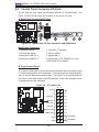
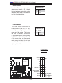
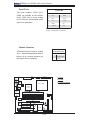
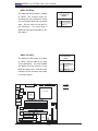
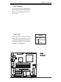
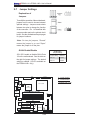
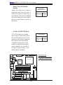
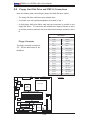
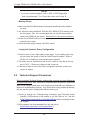
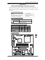
Power Fault
PWR Fault
Pin Definitions
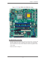
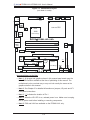
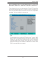
Connect a cable from your power supply to
the Power Fault header (PW3) to provide
warning of power supply failure. This warning signal is passed through the PWR_LED
pin to indicate of a power failure on the
chassis. See the table on the right for pin
Pin#
Definition
1
Pin 1 Fail Signal
2
Pin 2 Fail Signal
3
Pin 3 Fail Signal
4
Pin 4 Fail Signal
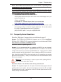
Note: This feature is only available when using
definitions.
redundant Supermicro power supplies.
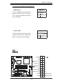
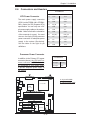
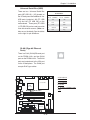
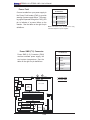
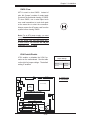
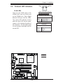
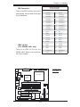
Power SMB (I2 C) Connector
PWR SMB
Pin Definitions
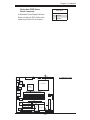
Power SMB (I2 C) Connector (PW4)
monitors onboard power supply, fan
and system temperature. See the
table on the right for pin definitions.
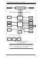
PWR SMB PWR Fault
CPU
Fan
JPR1
KB/MS
Fan1
COM1
VGA
(*LN2+)
JPL1
JPL2
LGA 775 CPU
Intel
3000
North Bridge
SUPER
®
PDSML-LN1+/LN2+
DIMM 1A
DIMM 1B
DIMM 2B
S I/O
JF1
2
JI C1
2
JI C2
IPMI
SBX: PCI-33 MHz
COM2
Battery
J10
BIOS
SPKR
PCI-33 MHz
Floppy
PCI1
JL1
ICH7R
South Bridge
USB3/4 USB5/6
JBT1
SATA1 SATA3
SATA0 SATA2
2-20
Fan4
JPG1
Slot4
VGA
Memory
PCI-E x4
IDE
J8
JWOR
Slot5
WOL
PCI-E x8
JLED
Slot6
LE4 LE3
LE1
VGA
CTRL
Buzzer
Fan5
(*LN2+)
FP CTRL
Fan2
Fan3 JPF
DIMM 2A
JLAN2
Clock
2
Data
3
PWR Fail
4
Ground
5
+3.3V
B. Power SMB
LAN
CTRL2
JLAN1
1
A. Power Fault
8-pin PWR
USB 1/2
LAN
CTRL1
Definition
A
B
24-Pin ATX PWR Fan6
Pin#