1
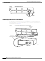
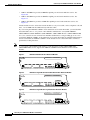
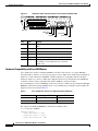
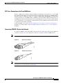
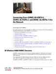
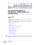
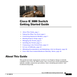
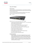
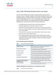
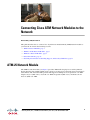
Connecting Cisco ATM Network Modules to the
Network
Revised: May 1, 2008, OL-12815-01
This guide describes how to connect Cisco Asynchronous Transfer Mode (ATM) network modules to
your network. It contains the following sections:
•
ATM-25 Network Module, page 1
•
ATM T3 and E3 Network Modules, page 3
•
ATM OC-3 Network Modules, page 5
•
Related Documents, page 17
•
Obtaining Documentation, Obtaining Support, and Security Guidelines, page 17
ATM-25 Network Module
The ATM-25 network module (see Figure 1) provides ATM traffic shaping for use with asymmetric
digital subscriber line (ADSL) uplink speeds, and protocol support for permanent virtual circuit (PVC)
environments. The network module provides full support for multiprotocol encapsulation over ATM
Adaptive Layer 5 (RFC 1483), classic IP over ATM encapsulation (RFC 1577), and Point-to-Point
Protocol (PPP) over ATM.
Americas Headquarters:
Cisco Systems, Inc., 170 West Tasman Drive, San Jose, CA 95134-1706 USA
Connecting Cisco ATM Network Modules to the Network
ATM-25 Network Module
Figure 1
ATM-25 Network Module
ATM 25Mbps
ATM-25
ATM 0
RX
EN
ATM traffic
LEDs
11705
TX
Enable LED
RJ-45 port
Connecting ATM-25 Ports to the Network
The ATM-25 port is a standard RJ-45 jack, color-coded light green. Use a straight-through modular
RJ-45 UTP Category 3, 4, or 5 cable or STP Category 1, 1A, 9, or 9A cable to connect the port to an
external ADSL modem. See Figure 2.
Figure 2
Connecting the ATM-25 Module to an ADSL Modem
ATM-25 port
(RJ-45)
ATM
25MbPS
ATM 0
TX
RX
EN
ADSL modem
Connecting Cisco ATM Network Modules to the Network
2
11707
Straight-through
RJ-45-to-RJ-45 cable
Connecting Cisco ATM Network Modules to the Network
ATM T3 and E3 Network Modules
ATM-25 Network Module LEDs
Figure 3 shows ATM-25 network module LEDs.
Figure 3
ATM-25 Network Module LEDs
ATM 25Mbps
ATM-25
ATM 0
RX
EN
ATM traffic
LEDs
11708
TX
Enable LED
All network modules have an enable (EN) LED. The enable LED indicates that the module has passed
its self-tests and is available to the router. The ATM-25 network module has the additional LEDs shown
in Table 1.
Table 1
ATM-25 Network Module LEDs
LED
Meaning
RX
Module is receiving ATM traffic
TX
Module is transmitting ATM traffic
ATM T3 and E3 Network Modules
ATM T3 and E3 network modules provide T3 and E3 ATM connectivity for high-bandwidth data
applications. There are three versions of these network modules: the ATM T3 Network Module, the ATM
E3 Network Module, and the ATM T3/E3 Network Module. See Figure 4, Figure 5 and Figure 6. These
network modules offer full support for multiprotocol encapsulation over ATM Adaptive Layer 5
(RFC 1483), classic IP over ATM encapsulation (RFC 1577), Point-to-Point Protocol (PPP) over ATM,
and LAN Emulation (LANE). Up to 1024 virtual circuits (VCs) are supported on the ATM T3/E3
network modules.
Figure 4
ATM Network Module with T3 Interface
ATM
1A-T3
SEE MANUAL BEFORE INSTALLING NETWORK MODULE
ATM 0
FERF OOF AIS
RX
RCLK
EN
30546
TX
Connecting Cisco ATM Network Modules to the Network
3
Connecting Cisco ATM Network Modules to the Network
ATM T3 and E3 Network Modules
Figure 5
ATM Network Module with E3 Interface
ATM
1A-E3
SEE MANUAL BEFORE INSTALLING NETWORK MODULE
ATM 0
FERF OOF AIS
Figure 6
RX
RCLK
EN
30543
TX
ATM Network Module with one T3/E3 Interface
ATM
NM-1A-T3/E3
ATM 0
LP
Note
SEE MANUAL BEFORE INSTALLING NETWORK MODULE
RX
TXCL
RXCL
RXCR RXALM
EN
155792
TX
The ATM T3 network module has a sensitive receiver. If you use a short T3 cable, it is possible to
saturate the receiver, leading to bit errors. If this occurs, we recommend one of the following:
•
Reduce the transmit level of the device attached to the T3 network module. Many devices have a line
build-out (LBO) configuration setting for this purpose.
•
Insert a 4-dB attenuator on the receive side of the T3 network module.
Connecting ATM T3 and E3 Ports to the Network
Use a coaxial cable to connect the module BNC port to a T3 or E3 network.
ATM T3 Network Module and ATM E3 Network Module LEDs
The ATM T3 network module and the ATM E3 network module have the LEDs shown in Table 2.
Table 2
ATM T3 Network Module and ATM E3 Network module LEDs
LED
Color
Meaning
EN
Green
Module has passed its self-tests and is available to the router.
RCLK Green
Receive clock has been detected.
FERF
Yellow
Far-end receive failure.
OOF
Yellow
Out of frame.
AIS
Yellow
Alarm indication signal.
Connecting Cisco ATM Network Modules to the Network
4
Connecting Cisco ATM Network Modules to the Network
ATM OC-3 Network Modules
ATM T3/E3 Network Module LEDs
Table 3 shows the LEDs for the combined ATM T3/E3 network module.
Table 3
ATM T3/E3 Network Module LEDs
LED
Color
Meaning
TXCL
Green
Cell transmitted.
RXCL
Green
Cell received.
RXALM
Yellow
Alarm indication signal.
RXCR
Green
Carrier present.
Loopback LED Green
Loopback
ATM OC-3 Network Modules
ATM OC-3 network modules provide full 155-Mbps ATM connectivity, including STS-3c and STM-1
framing, for high-bandwidth data applications and voice-data integration applications. Characteristics
and installation of these modules are described in the following sections.
•
OC-3 Network Modules for Cisco 3600 and Cisco 3700 Series Routers, page 5
•
ATM-OC3-POM Network Module for Cisco 3800 Series Routers, page 10
•
Laser Safety Guidelines, page 13
•
Fiber-Optic Transmission Specifications, page 14
OC-3 Network Modules for Cisco 3600 and Cisco 3700 Series Routers
This section describes the following OC-3 (Optical Carrier level 3) network modules for most
Cisco 3600 and Cisco 3700 series routers.
Note
ATM OC-3 network modules are not supported by the Cisco 3631 router.
The following modules are supported on the Cisco 3600 series routers and the Cisco 3725 router:
•
NM-1A-OC3MM provides a multimode (MM) fiber uplink port. See Figure 7.
•
NM-1A-OC3SMI provides a single-mode intermediate-reach (SMI) fiber uplink port. See Figure 8.
•
NM-1A-OC3SML provides a single-mode long-reach (SML) fiber uplink port. See Figure 9.
The following modules are supported on the Cisco 3745 router:
•
NM-1A-OC3MM-EP provides an MM fiber uplink port with enhanced performance. See Figure 7
for a similar faceplate.
•
NM-1A-OC3SMI-EP provides an SMI fiber uplink port with enhanced performance. See Figure 8
for a similar faceplate.
•
NM-1A-OC3SML-EP provides an SML fiber uplink port with enhanced performance. See Figure 9
for a similar faceplate.
The following modules are supported on the Cisco 3600 series routers:
Connecting Cisco ATM Network Modules to the Network
5
Connecting Cisco ATM Network Modules to the Network
ATM OC-3 Network Modules
•
NM-1A-OC3MM-1V provides an MM fiber uplink port and circuit emulation service. See
Figure 10.
•
NM-1A-OC3SMI-1V provides an SMI fiber uplink port and circuit emulation service. See
Figure 11.
•
NM-1A-OC3SML-1V provides an SML fiber uplink port and circuit emulation service. See
Figure 12.
Circuit emulation service allows the network module to carry voice traffic, such as telephone calls and
faxes, over an ATM network simultaneously with data traffic.
If you are using the ATM OC-3/STM-1 circuit emulation service network module, you need both the
network module and a 1- or 2-port T1 or E1 multiflex trunk interface card (VWIC-1MFT-T1,
VWIC-1MFT-E1, VWIC-2MFT-T1, VWIC-2MFT-E1, VWIC-2MFT-T1-DI, or VWIC-2MFT-E1-DI)
for a voice connection. You can install one multiflex trunk interface card (providing up to two voice
ports) in the ATM OC-3/STM-1 circuit emulation service network module. If a multiflex trunk interface
card is not installed, the ATM OC-3/STM-1 circuit emulation service network module continues to
perform data-routing functions.
Note
1- or 2-port T1 or E1 multiflex trunk interface cards that support G.703 (VWIC-1MFT-G703,
VWIC-2MFT-G703) are not supported in ATM OC-3/STM-1 circuit emulation service network
modules.
Figure 7
ATM OC-3 Multimode Fiber Network Module
ATM
CLASS 1 LASER PRODUCT
LASERPRODUCT DER KLASSE 1
1A-OC3MM
PRODUCT LASER DE CLASSE1
PRODUCTO LASER CLASE 1
ATM 0
EN
AIS
14860
RCLK FERF OOF
Figure 8
ATM OC-3 Single-Mode Intermediate-Reach Fiber Network Module
ATM
CLASS 1 LASER PRODUCT
LASERPRODUCT DER KLASSE 1
1A-OC3SMI
PRODUCT LASER DE CLASSE1
PRODUCTO LASER CLASE 1
ATM 0
EN
AIS
14858
RCLK FERF OOF
Figure 9
ATM OC-3 Single-Mode Long-Reach Fiber Network Module
ATM
1A-OC3SML
CLASS 1 LASER PRODUCT
LASERPRODUCT DER KLASSE 1
PRODUCT LASER DE CLASSE1
PRODUCTO LASER CLASE 1
ATM 0
AIS
EN
14859
RCLK FERF OOF
Connecting Cisco ATM Network Modules to the Network
6
Connecting Cisco ATM Network Modules to the Network
ATM OC-3 Network Modules
Figure 10
ATM OC-3/STM-1 Circuit Emulation Service Multimode Fiber Network Module
ATM
1A-OC3
MM-1V
CES
ATM 0
TX
Figure 11
RX
RCLK
FERF OOF AIS
EN
18705
VO
ATM OC-3/STM-1 Circuit Emulation Service Single-Mode Intermediate-Reach Fiber
Network Module
ATM
1A-OC3
SMI-1V
CES
CLASS 1 LASER PRODUCT
PRODUIT LASER DE CLASSE 1
LASERPRODUKT DER KLASSE 1
PRODUCTO LASER CLASE 1
1
ATM 0
Figure 12
RX
FERF OOF AIS
RCLK
EN
18704
TX
VO
ATM OC-3/STM-1 Circuit Emulation Service Single-Mode Long-Reach Fiber
Network Module
ATM
1A-OC3
SML-1V
CES
CLASS 1 LASER PRODUCT
PRODUIT LASER DE CLASSE 1
LASERPRODUKT DER KLASSE 1
PRODUCTO LASER CLASE 1
1
ATM 0
FERF OOF
RX
AIS
RCLK
EN
18703
TX
V0
ATM OC-3 Network Module LEDs
Figure 13 and Figure 14 show ATM OC-3 network module LEDs.
ATM
1A-OC3MM
ATM OC-3 Network Module LEDs
CLASS 1 LASER PRODUCT
LASERPRODUCT DER KLASSE 1
PRODUCT LASER DE CLASSE1
PRODUCTO LASER CLASE 1
ATM 0
RCLK FERF OOF
EN
AIS
14861
Figure 13
RCLK LED
FERF LED
OOF LED
AIS LED
OC-3
Enable LED
Connecting Cisco ATM Network Modules to the Network
7
Connecting Cisco ATM Network Modules to the Network
ATM OC-3 Network Modules
Figure 14
ATM OC-3/STM-1 Circuit Emulation Service Network Module LEDs
ATM
1A-OC3
MM-1V
CES
ATM 0
TX
RX
RCLK
FERF OOF AIS
EN
26912
VO
CES LED
FERF LED
OOF LED
AIS LED
RCLK LED
Enable LED
LED
Color
Meaning
EN
Green
Module has passed its self-tests and is available to the
router.
RCLK
Green
Receive clock has been detected.
FERF
Yellow
Far-end receive failure.
OOF
Yellow
Out of frame.
AIS
Yellow
Alarm indication signal.
CES
Green
An active CES connection is established (ATM
OC-3/STM-1 circuit emulation service network
module only).
Hardware Compatibility with Cisco 3620 Routers
Cisco 3620 routers require a minimum PCMCIA controller revision level to recognize ATM OC-3
network modules; otherwise, an error message appears. Cisco 3620 routers installed in the field before
April 1999 contain a Revision C PCMCIA controller, which is not compatible with these modules.
Starting in April 1999, all Cisco 3620 routers shipped from the factory include Revision E PCMCIA
controllers, which are fully compatible with all three ATM OC-3 network modules.
You can identify the version of PCMCIA controller in your Cisco 3620 router by entering the show pci
hardware command in privileged EXEC mode, or by examining the part number on the motherboard.
Supported versions are shown in Table 4.
Table 4
Cisco 3620 Router Versions for ATM OC-3 Network Modules
Does Not Support ATM OC-3
Supports ATM OC-3
PCMCIA controller
0x22, 0xE2
0x20, 0xE0
Motherboard
73-1850-10 and older
73-1850-11 or newer
The output of the show pci hardware command looks similar to this:
Router# show pci hardware
CLPD6729 registers:
(0x00) Chip Revision = 0x82
(0x1E) Misc Control 2 = 0x08
(0x1F) Chip Information = 0xE2
Connecting Cisco ATM Network Modules to the Network
8
Connecting Cisco ATM Network Modules to the Network
ATM OC-3 Network Modules
CES Cross-Connection on the Cisco 3660 Router
The Cisco 3660 router can deliver traditional PCM-encoded 64-kbps circuit-based voice over the ATM
OC-3 CES network module. To use this functionality, the multiservice interchange card (MIX) must be
installed on the Cisco 3660 router. T1/E voice channels on NM-xFE2W and NM-HDV network modules
can be transported across the MIX module to ATM OC-3 network modules (NM-1A-OC3XX-1V) over
an ATM network. PVC-based (permanent virtual circuit) CES allows service providers to quickly deliver
local or long distance voice, while SVC (switched virtual circuit) capabilities ensure that these services
are optimized for maximum profitability.
To install the MIX card, see the Installing the Multiservice Interchange Card in Cisco 3660 Routers
document. To configure CES, see the OC-3/STM-1 ATM Circuit Emulation Service Network Module
document.
Connecting ATM OC-3 Ports to the Network
To connect an ATM OC-3 network module to the network, insert a fiber-optic cable with one duplex SC
connector (see Figure 15) or two simplex SC connectors (see Figure 16) into the ATM interface.
Some network modules are shipped with a dust plug to protect this interface. Pull to remove it.
Figure 15
Duplex SC Connector
Figure 16
Simplex SC Connector
H2399
H2214
Note
Note
Cisco does not sell these fiber-optic cables, but they are available from many cable vendors. Cables
should perform to the specifications listed in Table 5.
Connecting Cisco ATM Network Modules to the Network
9
Connecting Cisco ATM Network Modules to the Network
ATM OC-3 Network Modules
Table 5
Note
Fiber-Optic Cable Specifications
Standard
Maximum Path Length
Cabling
ISO/IEC 9314-3
1.24 miles (2 km) all cables 62.5-micron core with an
in a connection, end to end optical loss of 0 to 9 dB, or
50-micron core with an
optical loss of 7 dB
IEC 793-2
27.9 miles (45 km) for SML 9-micron core
and 9.3 miles (15 km) for
SMI
ANSI/TIA/EIA-492
CAAA
27.9 miles (45 km) for SML 9-micron core
and 9.3 miles (15 km) for
SMI
A single fiber link should not mix 62.5- and 50-micron cable.
ATM-OC3-POM Network Module for Cisco 3800 Series Routers
The NM-1A-OC3-POM network module provides a high-performance fiber uplink port for Cisco 3800
series integrated services routers. See Figure 17. Supported platforms are:
•
Cisco 3825 integrated services router
•
Cisco 3845 integrated services router
Figure 17
ATM OC3-POM Network Module
ATM
NM-1A-OC3-POM
CLASS 1 LASER PRODUCT
LASERPRODUCT DER KLASSE 1
PRODUCT LASER DE CLASSE1
PRODUCTO LASER CLASE 1
RXCR RXCL TXCL RXALM
EN
127722
ATM 0
The ATM interface is the small form-factor pluggable (SFP) optical port labeled ATM 0. See Figure 17.
The optical interface is provided by an SFP module that is inserted into the SFP port. Fiber-optic cables
to the network are attached to the SFP module.
The network module has three modes of operation. The mode of operation is determined by the SFP
module that is used.
Caution
Only SFP modules provided by Cisco should be used in the network module. SFP modules that are not
provided by Cisco have not been evaluated for reliability or user safety.
The modes of operation and usable SFP modules are:
•
Multimode (MM)
– POM-OC3-MM
Connecting Cisco ATM Network Modules to the Network
10
Connecting Cisco ATM Network Modules to the Network
ATM OC-3 Network Modules
– SFP-OC3-MM
•
Single-mode intermediate reach (SMI)
– POM-OC3-SMIR
– SFP-OC3-IR1
•
Single-mode long reach (SML)
– POM-OC3-SMLR
– SFP-OC3-LR1
ATM-OC3-POM Network Module LEDs
Table 6 describes the functions of the LEDs on the ATM-OC3-POM network module shown in
Figure 17.
Table 6
ATM-OC3-POM LED Functions
LED
Color
Meaning
RXCR
Green
Lit when carrier signal into the network module is present.
RXCL
Green
Blinks to indicate packet reception.
TXCL
Green
Blinks to indicate packet transmission.
RXALM
Yellow
Alarm indication signal.
EN
Green
Module has passed its self-tests and is available to the router.
Connecting ATM-OC3-POM Ports to the Network
The following sections describe how to remove and install SFP modules, and how to connect the ports
on a module to the network.
Handling an SFP Module
Before handling an SFP module, observe the following guidelines:
Note
•
SFP modules are static-sensitive. To prevent electrostatic discharge (ESD) damage, follow your
normal board- and component-handling procedures.
•
SFP modules are dust-sensitive. When storing an SFP module or when a fiber-optics cable is not
plugged into the connector, always keep plugs in SFP module optical bores.
The most common source of contaminants in the optical bores is debris picked up on the ferrules of the
optical connectors. Use alcohol swabs or lint-free absorbent wipes to clean the ferrules of the optical
connector.
Removing an SFP Module
The following procedure describes removing an SFP module from the network module.
Connecting Cisco ATM Network Modules to the Network
11
Connecting Cisco ATM Network Modules to the Network
ATM OC-3 Network Modules
Warning
Ultimate disposal of this product should be handled according to all national laws and regulations.
Statement 1040
Caution
You can remove and install SFP modules with power on to the system; however, we strongly recommend
that you do not remove or install an SFP module with optical fiber cables attached.
To remove an SFP module, perform the following steps:
Step 1
Attach an ESD wrist strap to your wrist and to the ESD connection socket on the chassis or to a bare
metal surface on the chassis or frame.
Step 2
Disconnect the network fiber cable from the SFP module connector.
Step 3
Remove the SFP module from the slot.
a.
Using your thumb and forefinger, grip the colored latching band on the front of the SFP module.
b.
Gently push the latching band back toward the SFP port. You may hear a click or feel the SFP
module disengage from the holding latch.
Note
c.
Step 4
Not all SFP modules have the same kind of latching mechanism.
While still holding the latching band, pull the SFP module forward and out of the slot.
Set the SFP module aside on an antistatic surface.
Installing an SFP Module
Use the following procedure to install an SFP module:
Step 1
Attach an ESD-preventive wrist strap to your wrist and between yourself and an unpainted chassis
surface.
Step 2
Verify that you have the correct SFP module for your installation.
•
Check the part number and distance information on the SFP module label.
•
Alternatively, if the distance information is not on the label, use the show contr pos x/y command
to display the information after the SFP module is installed.
Step 3
Align the SFP module with the slot so that the label is facing away from the handle.
Step 4
Holding the module at the latching band (with your thumb and forefinger), insert the SFP module into
the slot on the SFP port. See Figure 18.
Connecting Cisco ATM Network Modules to the Network
12
Connecting Cisco ATM Network Modules to the Network
ATM OC-3 Network Modules
Figure 18
Installing an SFP Module
ATM
NM1A-O
C3-P
OM
CLA
S
LAS S 1 LA
S
ERP
ROD ER PRO
D
UCT
DER UCT
KLA
SSE
1
PRO
D
PRO UCT L
DUC ASER
TO L
D
ASE E CLA
S
RC
LAS SE1
E1
RXC
RR
XCL
TXC
L R
XAL
M
ATM
0
135226
EN
Step 5
Push the module back into the slot until the latch engages. When fully inserted, only the band around the
front of the SFP module should be visible.
Step 6
Remove the plug from the SFP module optical bores and save the plug for future use.
Step 7
Attach the network interface fiber-optic cable, as described in the “Connecting ATM OC-3 Ports to the
Network” section on page 9.
Laser Safety Guidelines
ATM OC-3 network modules use a small laser to generate the fiber-optic signal. Keep the transmit port
covered whenever a cable is not connected to it.
Warning
Because invisible laser radiation may be emitted from the aperture of the port when no fiber cable is
connected, avoid exposure to laser radiation and do not stare into open apertures. Statement 240
The module faceplate carries a Class 1 laser warning label. See Figure 19.
Connecting Cisco ATM Network Modules to the Network
13
Connecting Cisco ATM Network Modules to the Network
ATM OC-3 Network Modules
Figure 19
Class 1 Laser Warning Label
CLASS 1 LASER PRODUCT
LASERPRODUKT DER KLASSE 1
ATM
PRODUIT LASER DE CLASSE 1
PRODUCTO LASER CLASE 1
CLASS 1 LASER PRODUCT
LASERPRODUCT DER KLASSE 1
1A-OC3MM
PRODUCT LASER DE CLASSE1
PRODUCTO LASER CLASE 1
ATM 0
AIS
EN
14862
RCLK FERF OOF
Fiber-Optic Transmission Specifications
This section describes Synchronous Optical Network (SONET) specifications for fiber-optic
transmissions, defines the power budget, and helps you estimate your power margin for multimode and
single-mode transmissions. This section contains the following information:
•
SONET Distance Limitations
•
Power Budget and Power Margin
•
Link Loss
•
Estimating the Power Margin
•
Single-Mode Transmission
SONET Distance Limitations
The SONET specification for fiber-optic transmission defines two types of fiber, single-mode and
multimode. Single-mode fiber allows only one bundle of light rays to propagate through the fiber,
whereas multimode fiber allows multiple bundles entering at different angles. Because different bundles
(referred to as modes) travel different distances, depending on the entry angle, they arrive at the
destination at different times (modal dispersion). Single-mode fiber is capable of higher bandwidth and
greater cable run distances than multimode fiber.
Table 7 lists typical maximum distances for single-mode and multimode transmissions, as defined by
SONET. Use the calculations described in this section to determine the actual maximum for your
network. If the distance between two connected stations exceeds this limit, transmission can become
unreliable.
Table 7
Typical SONET Maximum Fiber-Optic Transmission Distances
Transceiver Type
Maximum Distance Between Stations
MM
1.5 miles (2 km)
SMI
9 miles (15 km)
SML
28 miles (40 km)
Connecting Cisco ATM Network Modules to the Network
14
Connecting Cisco ATM Network Modules to the Network
ATM OC-3 Network Modules
Power Budget and Power Margin
Proper operation of an optical data link depends on modulated light reaching the receiver with enough
power to be demodulated. The power budget (PB) is the difference between transmitter power (PT) and
receiver sensitivity (PR). For instance, if transmitter power is –20 dB and receiver sensitivity is –30 dB,
the power budget is 10 dB:
PB = PT – PR
PB = –20 dB – (–30 dB)
PB = 10 dB
The SONET specification requires that the signal meet the worst-case requirements listed in Table 8.
Table 8
SONET Signal Requirements
MM
SMI
SML
Transmitter power
–20 dBm –15 dBm –5 dBm
Receiver sensitivity
–30 dBm –31 dBm –34 dBm
Power budget
10 dBm
16 dBm
29 dBm
The difference between the power budget and the link loss (LL) is called the power margin (PM). If the
power margin is zero or positive, the link should work. If it is negative, the signal may not arrive with
enough power to operate the receiver.
Link Loss
Power loss over a fiber-optic link arises from the following causes:
•
Passive components—Attenuation caused by cables, cable splices, and connectors is common to
both multimode and single-mode transmission. Attenuation is significantly lower for optical fiber
than for other media.
•
Chromatic dispersion—The signal spreads in time because of differing speeds of the different
wavelengths of light.
•
Modal dispersion—In multimode fiber, the signal spreads in time because of the different
propagation modes.
•
Higher-order mode loss (HOL)—This loss results from light radiated into the fiber cladding.
•
Clock recovery at the receiver—This recovery consumes a small amount of power.
The power lost over the data link is the sum of all these losses. Table 9 gives an estimate of the amount
of loss attributable to each cause.
Table 9
Link Loss Causes and Amounts
Cause
Amount of Loss
Fiber attenuation
SM: 0.5 dB/km
MM: 1 dB/km
Splice
0.5 dB
Connector
0.5 dB
Modal and chromatic dispersion Depends on fiber and wavelength1
Connecting Cisco ATM Network Modules to the Network
15
Connecting Cisco ATM Network Modules to the Network
ATM OC-3 Network Modules
Table 9
Link Loss Causes and Amounts
Cause
Amount of Loss
Higher-order mode losses
0.5 dB
Clock recovery
1 dB
1. Dispersion is usually negligible for single-mode fiber. For multimode fiber, the product of bandwidth and distance should be
less than 500 MHz-km.
Estimating the Power Margin
The following example calculates a multimode power margin based on these values:
•
Power budget 10 dB (SONET worst-case specification for multimode fiber)
•
Link length 3 km
•
Four connectors
•
Three splices
•
Higher-order loss (HOL)
•
Clock recovery
The power margin is:
PM = PB – LL
= 10 dB – [3 km x (1.0 dB/km) + 4 x (0.5 dB) + 3 x (0.5 dB) + 0.5 dB + 1 dB] = 2 dB
The positive result means this link should have enough power for transmission. The product of
bandwidth and distance is 155 MHz x 3 km = 465 MHz-km; this is within the dispersion limit of
500 MHz-km.
Single-Mode Transmission
Single-mode transmission is useful for longer distances, because there is a single transmission path
within the fiber and modal dispersion does not occur.
The maximum receive power for SML is –10 dBm, and the maximum transmit power is 0 dBm. The
SML receiver can be overloaded when using short lengths of fiber. Overloading the receiver does not
damage it, but can cause unreliable operation. To prevent overloading an SML receiver, insert a
minimum 10-dB attenuator on the link between any SML transmitter and the receiver.
The SMI receiver cannot be overloaded by the SMI transmitter and does not require a minimum fiber
cable length or loss.
The following example of a single-mode power margin assumes these values:
•
Power budget 16 dB (SONET worst-case specification for SMI)
•
Two buildings 8 kilometers apart
•
Connections through a patch panel in an intervening building with a total of 12 connectors
PM = PB – LL
= 16 dB – 8 km x (0.5 dB/km) – 12 x (0.5 dB)
= 6 dB
The positive value means this link should have enough power for transmission.
Connecting Cisco ATM Network Modules to the Network
16
Connecting Cisco ATM Network Modules to the Network
Related Documents
Related Documents
For additional information, see the following documents and resources.
Related Topic
Document Title
Regulatory compliance and safety
information
Cisco Network Modules and Interface Cards Regulatory Compliance and Safety
Information
http://www.cisco.com/en/US/docs/routers/access/interfaces/rcsi/IOHrcsi.html
Cisco IOS software website and reference
documentation
Cisco IOS Software
http://www.cisco.com/web/psa/products/index.html?c=268438303
Obtaining Documentation, Obtaining Support, and Security
Guidelines
For information on obtaining documentation, obtaining support, providing documentation feedback,
security guidelines, and also recommended aliases and general Cisco documents, see the monthly
What’s New in Cisco Product Documentation, which also lists all new and revised Cisco technical
documentation, at:
http://www.cisco.com/en/US/docs/general/whatsnew/whatsnew.html
CCDE, CCENT, Cisco Eos, Cisco Lumin, Cisco StadiumVision, the Cisco logo, DCE, and Welcome to the Human Network are trademarks;
Changing the Way We Work, Live, Play, and Learn is a service mark; and Access Registrar, Aironet, AsyncOS, Bringing the Meeting To You,
Catalyst, CCDA, CCDP, CCIE, CCIP, CCNA, CCNP, CCSP, CCVP, Cisco, the Cisco Certified Internetwork Expert logo, Cisco IOS, Cisco Press,
Cisco Systems, Cisco Systems Capital, the Cisco Systems logo, Cisco Unity, Collaboration Without Limitation, EtherFast, EtherSwitch, Event
Center, Fast Step, Follow Me Browsing, FormShare, GigaDrive, HomeLink, Internet Quotient, IOS, iPhone, iQ Expertise, the iQ logo, iQ Net
Readiness Scorecard, iQuick Study, IronPort, the IronPort logo, LightStream, Linksys, MediaTone, MeetingPlace, MGX, Networkers, Networking
Academy, Network Registrar, PCNow, PIX, PowerPanels, ProConnect, ScriptShare, SenderBase, SMARTnet, Spectrum Expert, StackWise, The
Fastest Way to Increase Your Internet Quotient, TransPath, WebEx, and the WebEx logo are registered trademarks of Cisco Systems, Inc. and/or its
affiliates in the United States and certain other countries.
All other trademarks mentioned in this document or Website are the property of their respective owners. The use of the word partner does not imply
a partnership relationship between Cisco and any other company. (0804R)
Any Internet Protocol (IP) addresses used in this document are not intended to be actual addresses. Any examples, command display output, and
figures included in the document are shown for illustrative purposes only. Any use of actual IP addresses in illustrative content is unintentional and
coincidental.
© 2008 Cisco Systems, Inc. All rights reserved.
Connecting Cisco ATM Network Modules to the Network
17
Connecting Cisco ATM Network Modules to the Network
Obtaining Documentation, Obtaining Support, and Security Guidelines
Connecting Cisco ATM Network Modules to the Network
18