1
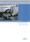
Hardware Installation Guide for Cisco UCS
E-Series Servers
First Published: October 19, 2012
Updated: October 19, 2012
This document provides information that you should know before and during installation of
Cisco UCS E-Series Servers in Cisco Integrated Services Routers (ISR G2), and contains the following
sections:
•
Cisco UCS E-Series Servers Overview, page 1
•
Recommended Practices for Cisco UCS E-Series Servers, page 11
•
Installing E-Series Servers in Cisco ISR G2 Routers, page 15
•
Where to Go Next, page 33
Cisco UCS E-Series Servers Overview
The Cisco UCS E-Series Servers (E-Series Servers) are the next generation of
Cisco UCS Express servers. E-Series Servers are a family of size, weight, and power efficient blade
servers that are housed within Generation 2 Cisco Integrated Services Routers (ISR G2). These servers
provide a general purpose compute platform for branch-office applications deployed either as bare-metal
on operating systems, such as Microsoft Windows or Linux; or as virtual machines on hypervisors, such
as VMware vSphere HypervisorTM, Microsoft Hyper-V, or Citrix XenServer.
Americas Headquarters:
Cisco Systems, Inc., 170 West Tasman Drive, San Jose, CA 95134-1706 USA
Hardware Installation Guide for Cisco UCS E-Series Servers
Hardware Requirements
Hardware Requirements
E-Series Servers reside in the Cisco 2900 series or 3900 series ISR G2. The following E-Series Servers
are supported:
•
UCS-E140S—Single-wide E-Series Server
•
UCS-E140D—Double-wide E-Series Server, 4 core CPU
•
UCS-E160D—Double-wide E-Series Server, 6 core CPU
•
UCS-E140DP—Double-wide E-Series Server, 4 core CPU, with PCIe
•
UCS-E160DP—Double-wide E-Series Server, 6 core CPU, with PCIe
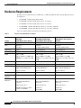
Table 1 provides hardware information about E-Series Servers.
Table 1
E-Series Server Hardware at a Glance
Feature
UCS-E140S
Single-Wide E-Series Server)
UCS-E140D and UCS-E160D
Double-Wide E-Series Servers
UCS-E140DP and UCS-E160DP
Double-Wide E-Series Servers
with PCIe
Form Factor
Single-wide SM
Double-wide SM
Double-wide SM
CPU
Intel Xeon
TM
Intel Xeon
TM
Intel XeonTM
E3-1105C
E5-2428L and E5-2418L
E5-2428L and E5-2418L
CPU Cores
4 Core
4 Core and 6 Core
4 Core and 6 Core
DIMM Slots
2 Slots
3 Slots
3 Slots
RAM
8 GB - 16 GB
8 GB - 48 GB
8 GB - 48 GB
Supports DDR3 1333MHz VLP
UDIMM 1.5 V, 4 GB, and 8 GB
Supports DDR3 1333 MHz
RDIMM 1.35 V, 4 GB, 8 GB and
16 GB
Supports DDR3 1333 MHz
RDIMM 1.35 V, 4 GB, 8 GB, and
16 GB
RAID
RAID 0 and RAID 1
RAID 0, RAID 1, and RAID 5
RAID 0 and RAID 1
Storage Type
SATA, SAS, SSD, and SED
SATA, SAS, SSD, and SED
SATA, SAS, SSD, and SED
HDD
SAS 10K RPM, SATA 7200
RPM, and SAS SSD Drives 1
SAS 10K RPM, SATA 7200 RPM, SAS 10K RPM, SATA 7200
and SAS SSD Drives1
RPM, and SAS SSD Drives1
Supports 2 Drives
Supports 3 Drives
Supports 2 Drives
Storage Capacity 200 GB - 2 TB
200 GB - 3 TB
200 GB - 2 TB
Internal Network 2 Gigabit Ethernet Interfaces
Interface
2 Gigabit Ethernet Interfaces
2 Gigabit Ethernet Interfaces
External
Interfaces
1 USB Connector
2 USB Connectors
2 USB Connectors
1 RJ-45 Gigabit Ethernet
Connector
2 RJ-45 Gigabit Ethernet
Connectors
2 RJ-45 Gigabit Ethernet
Connectors
1 Management Port
1 Management Port
1 Management Port
1 KVM Port (Supports VGA,
1 USB, 1 Serial DB9)
1 VGA Port
1 VGA Port
1 Serial DB9
1 Serial DB9
Cisco UCS E-Series Server Modules Hardware Installation Guide
2
OL-26447-01
Hardware Installation Guide for Cisco UCS E-Series Servers
Hardware Requirements
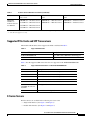
Table 1
E-Series Server Hardware at a Glance (continued)
2921, 29512, 3925, 3925e, 3945,
3945e
2921, 29512, 3925, 3925e, 3945,
3945e
2900 ISR G2—1 E-Series Server 2900 ISR G2—1 E-Series Server
2900 ISR G2—1 E-Series Server
2951 ISR G2—2 E-Series Servers 3900 ISR G2—1 E-Series Server
3900 ISR G2—1 E-Series Server
Router Platforms 2911, 2921, 2951, 3925, 3925e,
3945, 3945e
Maximum
Number of
E-Series Servers
Per ISR G2
3925 ISR G2—2 E-Series Servers
3945 ISR G2—4 E-Series Servers
1. All hardware drives within the E-Series Server must be installed with the same type of storage device; either all SAS drives or all SATA drives.
2. 2921 and 2951 support 4-core only.
Supported PCIe Cards and SFP Transceivers
The Double-wide E-Series Server supports the PCIe cards listed in Table 2.
Table 2
Supported PCIe Cards
PCIe Card SKU
Description
E100-PCIE10GEFCOE
1 port SFP+,PCIe,10GE fiber, FCOE support
E100-PCIE-4PGE
4 port GE, PCIe card, RJ-45
Table 3 lists the supported SFP transceivers that are supported on the E100-PCIE10GEFCOE.
Table 3
Supported SFP transceivers on the E100-PCIE10GEFCOE
SFP
Description
SFP-H10GB-CU1M
SFP+ 10GBASE-CU 1 Meter cable, passive
SFP-H10GB-CU3M
SFP+ 10GBASE-CU 3 Meter cable, passive
SFP-H10GB-CU5M
SFP+ 10GBASE-CU 5 Meter cable, passive
SFP-H10GB-ACU7M
SFP+ 10GBASE-CU 7 Meter cable, active
SFP-H10GB-ACU10M
SFP+ 10GBASE-CU 10 Meter cable, active
JDSU
(PLRXPL-SC-S43-22N) SFP+
SFP+ (Optical)
Cisco SFP-10G-SR
SFP+ 10GBase- SR (Optical)
E-Series Servers
E-Series Servers are available in the following two factor form:
•
Single-wide interface (See Figure 1 and Figure 3)
•
Double-wide interface (See Figure 4 and Figure 5)
Cisco UCS E-Series Server Modules Hardware Installation Guide
3
Hardware Installation Guide for Cisco UCS E-Series Servers
Hardware Requirements
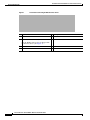
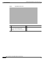
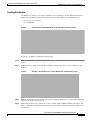
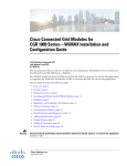
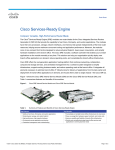
Figure 1
Front Panel of the Single-Wide E-Series Server
1
Gigabit Ethernet Port
2
Management Port
3
Power Switch
4
LEDs for HDD1
5
Keyboard, Video, Mouse (KVM) Port
6
Hard Disk Drive 1
USB
Use the KVM connector that is shipped with
the E-Series Server (See Figure 2)
7
LEDs for HDD2
8
9
Hard Disk Drive 2
10 Reset Switch
Cisco UCS E-Series Server Modules Hardware Installation Guide
4
OL-26447-01
Hardware Installation Guide for Cisco UCS E-Series Servers
Hardware Requirements
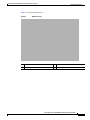
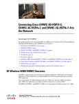
Figure 2 shows the KVM Connector
Figure 2
KVM Connector
1
USB Connector
3
DB9 Connector
2
DB15 Connector
Cisco UCS E-Series Server Modules Hardware Installation Guide
5
Hardware Installation Guide for Cisco UCS E-Series Servers
Hardware Requirements
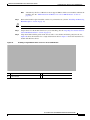
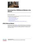
Figure 3
Single-Wide E-Series Server
1
DIMM Slots
2
HDD
3
SD0 (The SD card in the SD0 card slot
contains the Integrated Management
Controller software and should always be
present.)
4
SD1
Cisco UCS E-Series Server Modules Hardware Installation Guide
6
OL-26447-01
Hardware Installation Guide for Cisco UCS E-Series Servers
Hardware Requirements
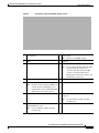
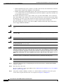
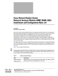
Figure 4
1
Front Panel of the Double-Wide E-Series Server
2
Power Switch
Reset Switch.
Note
This reset all CMOS settings.
3
LEDs
4
VGA Port
5
Serial Port
6
Dual SD card slots and cover
Note
Do not remove the SD card in the SD0
card slot when the system is in
operation. The SD card in the SD0
card slot contains the Integrated
Management Controller software and
should always be present.
7
Gigabit Ethernet Ports (GE2 and GE3)
8
9
USB Ports.
10 (Optional) HDD2, PCIe assembly or Blank
slot.
Note
Each port can provide up to 500 mA of
current. Devices with higher power
requirements, such as CD/DVD ROM
will need its own external power.
11 Hard Disk Drives (HDD0 and HDD1)
Management Port
12 (Optional) Alternate PCIe Assembly with
FCoE port
Note
For use with Cisco PCIe assembly
modules only.
13 (Optional) Alternate PCIe Assembly with
4-Gigabit Ethernet ports
Note
For use with Cisco PCIe assembly
modules only.
Cisco UCS E-Series Server Modules Hardware Installation Guide
7
Hardware Installation Guide for Cisco UCS E-Series Servers
Hardware Requirements
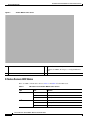
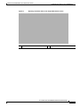
Figure 5
1
Double-Wide E-Series Server
2
DIMM slots
(Optional) PCIe assembly
Available for HDD2, FCoE port, or 4-Gigabit Ethernet
ports.
3
Hard Disk Drives (HDD0 and HDD1)
E-Series Servers LED States
There are LEDs on the E-Series Servers. Table 4 and Table 6 list the LED states.
Table 4
LED
M0
M1
1
2
LED States for the Double-Wide E-Series Servers
Color
Indicates
Off
No Memory installed in this socket
Green
Memory M0 is installed
Amber
Memory M0 is installed, but fault was detected
Off
No Memory installed in this socket
Green
Memory M1 is installed
Amber
Memory M1 is installed, but fault was detected
Cisco UCS E-Series Server Modules Hardware Installation Guide
8
OL-26447-01
Hardware Installation Guide for Cisco UCS E-Series Servers
Hardware Requirements
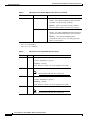
Table 4
LED
M2
3
HOT
D0A
LED States for the Double-Wide E-Series Servers (continued)
Color
Indicates
Off
No Memory installed in this socket
Green
Memory M2 is installed
Amber
Memory M2 is installed, but fault was detected
Green
Temperature is in range
Amber
A high temperature has been detected on the CPU, power
supply, or other internal sensors
Green
Status of hard drive activity is as follows:
• Steady—Hard Drive is present
• Blinking—Activity
• Off—Inactive or there is no power supplied to the CPU
D0F
Amber
Fault detected on the hard drive
D1A
Green
Status of hard drive activity is as follows:
• Steady—Hard Drive is present
• Blinking—Activity
• Off—Inactive or there is no power supplied to the CPU
D1F
Amber
Fault is detected on the hard drive
D2A
Green
If the optional hard drive is present, then the status of
hard drive activity is as follows:
•
Steady—Hard Drive is present
•
Blinking—Activity
•
Off—Inactive or there is no power supplied to the
CPU
If there is a PCIe card installed, the LED displays a
steady Green
D2F
Amber
Fault is detected on the hard drive
ACT
Green
Blinks when the processor is active
STS
Green
Operation is normal
Amber
Fault is detected on the processor
Green
Blinks when Cisco Integrated Management Controller is
operating normally
IMC
Cisco UCS E-Series Server Modules Hardware Installation Guide
9
Hardware Installation Guide for Cisco UCS E-Series Servers
Hardware Requirements
Table 4
LED States for the Double-Wide E-Series Servers (continued)
LED
Color
Indicates
Power LED
Green
Status is as follows:
Amber
•
Steady—Cisco Integrated Management Controller
and CPU are both operating normally
•
Blinking—CPU is operating normally and Cisco
Integrated Management Controller is booting up
Status is as follows:
•
Steady—Cisco Integrated Management Controller is
operating normally and the CPU is powered down
•
Blinking —Cisco Integrated Management
Controller is in the process of booting up and the
CPU is powered down
1. This is memory installed on the outermost DIMM slot.
2. This is the middle DIMM slot.
3. This is the innermost DIMM slot.
Table 5
LED
LED States for the Single-Wide E-Series Servers
Color
HDD 0 ACT Green
Indicates
Status of hard drive activity is as follows:
• Steady—Hard Drive is present
• Blinking—Activity
• Off—Inactive or there is no power supplied to the CPU
HDD0 FLT
Amber
The CPU is in use. Fault detected on the hard drive.
Note
HDD1 ACT
Green
The SYS LED will still show solid green.
Status of hard drive activity is as follows:
• Steady—Hard Drive is present
• Blinking—Activity
• Off—Inactive or there is no power supplied to the CPU
HDD1 FLT
Amber
The CPU is in use. Fault detected on the hard drive.
Note
The SYS LED will still show solid green.
Cisco UCS E-Series Server Modules Hardware Installation Guide
10
OL-26447-01
Hardware Installation Guide for Cisco UCS E-Series Servers
Recommended Practices for Cisco UCS E-Series Servers
Table 5
LED States for the Single-Wide E-Series Servers (continued)
LED
Color
Indicates
SYS
Green
Solid—Operation is normal
Note
If DRAM is not detected the SYS LED will still
show solid green.
Blinking—System is booting before entering EFI shell.
Amber
Power LED Green
Amber
Fault is detected on the processor
Status is as follows:
•
Steady—Cisco Integrated Management Controller and
CPU are both operating normally
•
Blinking—CPU is operating normally and Cisco
Integrated Management Controller is booting up
Status is as follows:
•
Steady—Cisco Integrated Management Controller is
operating normally and the CPU is powered down
•
Blinking —Cisco Integrated Management Controller is
in the process of booting up and the CPU is powered
down
Recommended Practices for Cisco UCS E-Series Servers
This section describes recommended practices for safe and effective installation of the hardware
described in this document, and includes the following sections:
•
Safety Recommendations, page 11
•
Preventing Electrostatic Discharge Damage, page 12
•
General Guidelines for Installing the E-Series Servers on a Rack, page 12
•
General Maintenance Guidelines for E-Series Servers, page 13
The safety warnings included in this section apply to all Cisco UCS E-Series Servers.
Safety Recommendations
To prevent hazardous conditions, follow these safety recommendations while working with this
equipment:
•
Keep tools away from walk areas where you or others could fall over them.
•
Do not wear loose clothing around the router. Fasten your tie or scarf and roll up your sleeves to
prevent clothing from being caught in the chassis.
•
Wear safety glasses when working under any conditions that might be hazardous to your eyes.
•
Locate the emergency power-off switch in the room before you start working. If an electrical
accident occurs, shut the power off.
Cisco UCS E-Series Server Modules Hardware Installation Guide
11
Hardware Installation Guide for Cisco UCS E-Series Servers
Recommended Practices for Cisco UCS E-Series Servers
•
Before working on the router, turn off the power and unplug the power cord.
•
Disconnect all power sources before doing the following:
– Installing or removing a router chassis
– Working near power supplies
•
Do not work alone if potentially hazardous conditions exist.
•
Always check that power is disconnected from a circuit.
•
Remove possible hazards from your work area, such as damp floors, ungrounded power extension
cables, or missing safety grounds.
•
If an electrical accident occurs, proceed as follows:
– Use caution; do not become a victim yourself.
– Turn off power to the room using the emergency power-off switch.
– If possible, send another person to get medical aid. Otherwise, determine the condition of the
victim and then call for help.
– Determine if the person needs rescue breathing or external cardiac compressions; then take
appropriate action.
Preventing Electrostatic Discharge Damage
Electrostatic discharge can damage equipment and impair electrical circuitry. Electrostatic discharge
occurs when electronic printed circuit cards, such as those used in Cisco service modules and network
modules, are improperly handled and can result in complete or intermittent equipment failure. Always
observe the following electrostatic discharge damage (ESD) prevention procedures when installing,
removing, and replacing E-Series Servers, Cisco service modules, Cisco network modules, Cisco
interface cards, Cisco expansion modules, or other electronic printed circuit cards:
Caution
•
Make sure that the router chassis is electrically connected to earth ground.
•
Wear an ESD-preventive wrist strap, and make sure that it makes good contact with your skin.
•
Connect the wrist strap clip to an unpainted portion of the chassis frame to channel unwanted ESD
voltages to ground.
•
If no wrist strap is available, ground yourself by touching the metal part of the router chassis.
The wrist strap and clip must be used correctly to ensure proper ESD protection. Periodically confirm
that the resistance value of the ESD-preventive wrist strap is between 1 and 10 megohms (Mohm).
General Guidelines for Installing the E-Series Servers on a Rack
Excessive vibration can result in the loss of data and disk drive failure. The E-Series Server with hard
disk drives should not be installed in a rack cabinet where it may be exposed to excessive high vibration.
Before you install the router and E-Series Server in the rack cabinet, review the following
recommendations:
Note
The E-Series Server with solid state drives can withstand higher vibration levels.
Cisco UCS E-Series Server Modules Hardware Installation Guide
12
OL-26447-01
Hardware Installation Guide for Cisco UCS E-Series Servers
Recommended Practices for Cisco UCS E-Series Servers
•
Install the server away from heating, ventilation, and air-conditioning (HVAC) system and other
large building air movers.
•
Install the rack away from areas that may be affected by external vibrations, such garage areas where
there may be moving vehicles or factories with heavy machinary.
•
Do not install in a rack that will be placed in a moving vehicle.
General Maintenance Guidelines for E-Series Servers
The following maintenance guidelines apply to E-Series Servers:
•
Keep the router chassis area clear and dust-free during and after installation.
•
If you remove the chassis cover for any reason, store it in a safe place.
•
Do not perform any action that creates a hazard to people or makes equipment unsafe.
•
Keep walk areas clear to prevent falls or damage to equipment.
•
Follow installation and maintenance procedures as documented by Cisco Systems, Inc.
Safety Warnings for E-Series Servers
The following safety warning statements apply to all hardware procedures involving E-Series Servers
for Cisco ISR G2 routers. Translations of these warnings are available in the Cisco Network Modules
and Interface Cards Regulatory Compliance and Safety Information document, which ships with
individual E-Series Server orders, and is also available online at
http://www.cisco.com/en/US/docs/routers/access/interfaces/rcsi/IOHrcsi.html
Warning
IMPORTANT SAFETY INSTRUCTIONS
This warning symbol means danger. You are in a situation that could cause bodily injury. Before you
work on any equipment, be aware of the hazards involved with electrical circuitry and be familiar
with standard practices for preventing accidents. Use the statement number provided at the end of
each warning to locate its translation in the translated safety warnings that accompanied this device.
Statement 1071
SAVE THESE INSTRUCTIONS
Warning
This warning symbol means danger. You are in a situation that could cause bodily injury. Before you
work on any equipment, be aware of the hazards involved with electrical circuitry and be familiar
with standard practices for preventing accidents. Use the statement number provided at the end of
each warning to locate its translation in the translated safety warnings that accompanied this device.
Statement 1071
Warning
Only trained and qualified personnel should be allowed to install or replace this equipment. Statement
1030
Cisco UCS E-Series Server Modules Hardware Installation Guide
13
Hardware Installation Guide for Cisco UCS E-Series Servers
Recommended Practices for Cisco UCS E-Series Servers
Warning
No user-serviceable parts inside. Do not open. Statement 1073
Warning
Ultimate disposal of this product should be handled according to all national laws and regulations.
Statement 1040
Warning
Read the installation instructions before connecting the system to the power source. Statement 1004
Warning
Installation of the equipment must comply with local and national electrical codes. Statement 1074
Warning
This unit might have more than one power supply connection. All connections must be removed to
de-energize the unit. Statement 1028
Warning
This equipment must be grounded. Never defeat the ground conductor or operate the equipment in the
absence of a suitably installed ground conductor. Contact the appropriate electrical inspection
authority or an electrician if you are uncertain that suitable grounding is available. Statement 1024
Warning
When installing or replacing the unit, the ground connection must always be made first and
disconnected last. Statement 1046
Warning
Do not use this product near water; for example, near a bath tub, wash bowl, kitchen sink or laundry
tub, in a wet basement, or near a swimming pool. Statement 1035
Warning
Never install telephone jacks in wet locations unless the jack is specifically designed for
wet locations. Statement 1036
Warning
Never touch uninsulated telephone wires or terminals unless the telephone line has been
disconnected at the network interface. Statement 1037
Warning
Avoid using a telephone (other than a cordless type) during an electrical storm. There may be a remote
risk of electric shock from lightning. Statement 1038
Warning
To report a gas leak, do not use a telephone in the vicinity of the leak. Statement 1039
Cisco UCS E-Series Server Modules Hardware Installation Guide
14
OL-26447-01
Hardware Installation Guide for Cisco UCS E-Series Servers
Installing E-Series Servers in Cisco ISR G2 Routers
Warning
Class 1 laser product. Statement 1008
Warning
Invisible laser radiation may be emitted from the end of the unterminated fiber cable or connector. Do
not view directly with optical instruments. Viewing the laser output with certain optical instruments
(for example, eye loupes, magnifiers, and microscopes) within a distance of 100 mm may pose an eye
hazard. Statement 1056
The following warnings apply in Australia:
Warning
Do not touch the power supply when the power cord is connected. For systems with a power switch,
line voltages are present within the power supply even when the power switch is OFF and the power
cord is connected. For systems without a power switch, line voltages are present within the power
supply when the power cord is connected. Statement 4
Warning
This equipment will be inoperable when mains power fails. Statement 198
Warning
To avoid electric shock, do not connect safety extra-low voltage (SELV) circuits to telephone-network
voltage (TNV) circuits. LAN ports contain SELV circuits, and WAN ports contain TNV circuits. Both
LAN and WAN ports may use RJ-45 connectors. Use caution when connecting cables. Statement 1021
Warning
Hazardous network voltages are present in WAN ports regardless of whether power to the router is
OFF or ON. To avoid electric shock, use caution when working near WAN ports. When detaching
cables, detach the end away from the router first. Statement 1026
Warning
Before opening the chassis, disconnect the telephone-network cables to avoid contact with
telephone-network voltages. Statement 1041
Warning
This equipment must be installed and maintained by service personnel as defined by AS/NZS 3260.
Incorrectly connecting this equipment to a general-purpose outlet could be hazardous. The
telecommunications lines must be disconnected 1) before unplugging the main power connector or 2)
while the housing is open, or both. Statement 1043
Installing E-Series Servers in Cisco ISR G2 Routers
This section describes the tasks for installing the E-Series Servers on Cisco ISR G2 routers, and contains
the following subsections:
•
Tools and Equipment Required During E-Series Servers Installation, page 16
•
Installing and Removing Blank Faceplates, page 17
Cisco UCS E-Series Server Modules Hardware Installation Guide
15
Hardware Installation Guide for Cisco UCS E-Series Servers
Installing E-Series Servers in Cisco ISR G2 Routers
– Installing Blank Faceplates on Cisco ISR G2 Routers, page 18
– Removing Blank Faceplates from Cisco ISR G2 Routers, page 18
•
Preparing Cisco Router Slots for Server Module Installation, page 18
– Installing Slot Dividers, page 19
– Removing Slot Dividers, page 20
– Installing the E-Series Servers, page 20
•
Note
Installing the E-Series Servers, page 20
Cisco 2900 series do not support online insertion and removal (OIR) of the E-Series Servers.
To avoid damaging the router, turn off the electrical power on the router and disconnect network cables
before inserting or removing the E-Series Servers into the Cisco 2900 routers.
Tools and Equipment Required During E-Series Servers Installation
You will need the following tools and equipment while working with E-Series Servers:
•
Number 1 Phillips screwdriver or a small flat-blade screwdriver
•
ESD-preventive wrist strap
•
(For routers using DC power) Tape to secure DC circuit breaker handle
Summary of Installation Tasks
When installing the E-Series Servers in a Cisco ISR G2 router, perform the following tasks:
Warning
Only trained and qualified personnel should be allowed to install, replace, or service this equipment.
Statement 1030
Warning
To avoid electric shock, do not connect safety extra-low voltage (SELV) circuits to telephone-network
voltage (TNV) circuits. LAN ports contain SELV circuits, and WAN ports contain TNV circuits. Some
LAN and WAN ports both use RJ-45 connectors. Use caution when connecting cables. Statement 1021
Warning
Hazardous network voltages are present in WAN ports regardless of whether power to the unit is OFF
or ON. To avoid electric shock, use caution when working near WAN ports. When detaching cables,
detach the end away from the unit first. Statement 1026
Caution
To prevent damage to the E-Series Servers, handle the E-Series module by the chassis or frame.
Cisco UCS E-Series Server Modules Hardware Installation Guide
16
OL-26447-01
Hardware Installation Guide for Cisco UCS E-Series Servers
Installing E-Series Servers in Cisco ISR G2 Routers
Cisco UCS E-Series Server Module Hardware Installation Tasks
Step 1
Connect the wrist strap clip to an unpainted portion of the chassis frame to channel unwanted ESD
voltages to ground.
Step 2
Turn off power to the router.
Note
Alternatively, the Cisco 3900 series routers support OI R for similar server modules and network
modules. (See the “Online Insertion and Removal on a Cisco ISR G2 Router” section on
page 22)
Step 3
Remove blank faceplates from the slots you plan to use. (See the “Removing Blank Faceplates from
Cisco ISR G2 Routers” section on page 18)
Step 4
Install the E-Series Servers. (See the “Installing the E-Series Servers” section on page 20)
Note
Be sure to install a blank faceplate on the other side of the slot when installing a single-wide
E-Series Server. (See the “Installing Blank Faceplates on Cisco ISR G2 Routers” section on
page 18)
Installing and Removing Blank Faceplates
All empty chassis slots on the Cisco ISR G2 router must be covered with blank faceplates to ensure
proper cooling airflow and to prevent electromagnetic interference.
Warning
Blank faceplates and cover panels serve three important functions: they prevent exposure to
hazardous voltages and currents inside the chassis; they contain electromagnetic interference (EMI)
that might disrupt other equipment; and they direct the flow of cooling air through the chassis. Do not
operate the system unless all cards, faceplates, front covers, and rear covers are in place. Statement
1029
Preparing to Install Blank Service Module Faceplates on a Double-Wide Slot
To install a faceplate on a Cisco ISR G2 Router service module (SM) slot, perform the following steps:
Step 1
Install a slot divider in the SM slot. (See the “Installing Slot Dividers” section on page 19)
Step 2
Install one blank faceplate over each slot. (See the “Installing Blank Faceplates on Cisco ISR G2
Routers” section on page 18)
Cisco UCS E-Series Server Modules Hardware Installation Guide
17
Hardware Installation Guide for Cisco UCS E-Series Servers
Installing E-Series Servers in Cisco ISR G2 Routers
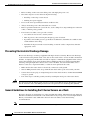
Installing Blank Faceplates on Cisco ISR G2 Routers
To install a blank faceplate, perform the following steps:
Step 1
Install the blank faceplate. See Figure 6.
•
(For blank faceplates with mounting screws) Align the captive screws with the screw holes on the
chassis. Using either a number 1 Phillips screwdriver or a small flat-blade screwdriver, tighten the
captive screws until the blank faceplate is flush with the chassis.
•
(For blank faceplates with tabs) Align the blank faceplate tabs with the slots on the chassis. Press
the blank faceplate against the chassis until the tabs pop into place. The blank faceplate is flush with
the chassis when properly installed.
Figure 6
Step 2
Service Module Blank Panel
Continue with hardware installation tasks.
Removing Blank Faceplates from Cisco ISR G2 Routers
To remove the faceplates from blank SM slot, perform the following steps:
Step 1
Tip
Step 2
Using either a number 1 Phillips screwdriver or a small flat-blade screwdriver, unscrew the captive
screws and remove the blank faceplate from the chassis slot you plan to use.
Save blank faceplates for future use.
Continue with hardware installation tasks.
Preparing Cisco Router Slots for Server Module Installation
Several Cisco ISR G2 routers have flexible SM slots to support various Cisco service module and server
module factors. Before installing a module, you may need to prepare the slot for the module’s particular
form factor.
Cisco UCS E-Series Server Modules Hardware Installation Guide
18
OL-26447-01
Hardware Installation Guide for Cisco UCS E-Series Servers
Installing E-Series Servers in Cisco ISR G2 Routers
Installing Slot Dividers
Slot dividers (see Figure 7) are used to customize service module slots for the different form factors
(Single-wide and Double-wide). Slot dividers are used on the following Cisco ISR G2 routers:
•
Cisco 2911, 2921, and 2951
•
Cisco 3900 series
Figure 7
Slot Divider for Service Module Slots (shown without retention screw)
To install a slot divider, perform the following steps:
Step 1
Remove any installed service modules, blank faceplates, and slot adapters from the router slot you plan
to use.
Step 2
Insert the top rails of the slot divider between the two guide rails in the top of the module slot. (See
Figure 8)
Figure 8
Inserting a Slot Divider into a Service Module Slot (with retention screw)
Step 3
Push the slot divider in until it is fully seated. Service module dividers have a long retention screw that
slides into the divider. (See Figure 8)
Step 4
Tighten the retention screw on the front of the slot divider with a number 1 Phillips screwdriver. (See
Figure 9) When the slot divider is fully inserted, its front surface is flush with the panel of the router.
(See Figure 9)
Cisco UCS E-Series Server Modules Hardware Installation Guide
19
Hardware Installation Guide for Cisco UCS E-Series Servers
Installing E-Series Servers in Cisco ISR G2 Routers
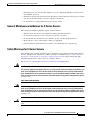
Figure 9
Step 5
Tightening the Slot Divider in a Service Module Slot
Proceed with hardware configuration tasks.
Removing Slot Dividers
Slot dividers are removed to permit use of double-wide E-Series Servers in modular router slots.
To remove slot dividers from module slots, perform the following steps:
Step 1
Remove any installed service modules, blank faceplates, and slot adapters from the router slot you plan
to use.
Step 2
Loosen the retention screw on the front of the slot divider.
Step 3
Pull the slot divider straight out of the module slot.
Step 4
Proceed with hardware configuration tasks.
Installing the E-Series Servers
Note
For Cisco 3900 ISR G2—If you are using PoE, and you want to install one double-wide E-Series Server
and any number of server modules in a a Cisco 3900 ISR G2, you must use a second AC and PoE supply
to support this configuration.
For example, you have a Cisco 3900 ISR G2 that has a PoE capable switch providing power to phones,
and you want to install a double-wide E-Series Server in one slot and one or two single-wide servers in
the other slots, then you must use a second AC and PoE supply to support this configuration.
E-Series Servers can be installed either before or after mounting the router, whichever is more
convenient. To install a E-Series Server, follow these steps:
Step 1
Turn off electrical power to the router. Leave the power cable plugged in to channel ESD voltages to
ground.
Cisco UCS E-Series Server Modules Hardware Installation Guide
20
OL-26447-01
Hardware Installation Guide for Cisco UCS E-Series Servers
Installing E-Series Servers in Cisco ISR G2 Routers
Note
Step 2
Tip
Figure 10
Alternatively, the Cisco 3900 series routers support OIR for similar server modules and network
modules. (See the “Online Insertion and Removal on a Cisco ISR G2 Router” section on
page 22.)
Remove the blank faceplates installed over the slot you intend to use. (See the “Installing and Removing
Blank Faceplates” section on page 17.)
Save blank faceplates for future use.
Step 3
Prepare the slot for the module form factor you are installing. (See the “Preparing Cisco Router Slots for
Server Module Installation” section on page 18.)
Step 4
Align the module with the guides in the chassis walls or slot divider and slide it gently into the slot.
Figure 10 shows the installation of a single-wide E-Series Server. Figure 11 shows the installation of a
double-wide E-Series Server.
Installing a Single-Wide E-Series Server in a Cisco ISR G2 Router
1
Single-wideE-Series Server
3
Router chassis
2
Slot Divider
Cisco UCS E-Series Server Modules Hardware Installation Guide
21
Hardware Installation Guide for Cisco UCS E-Series Servers
Installing E-Series Servers in Cisco ISR G2 Routers
Figure 11
1
Installing a Double-Wide E-Series Server in a Cisco ISR G2 Router
Double-wideE-Series Server
2
Router chassis
Step 5
Push the module into place until you feel the edge connector seat securely into the connector on the
router backplane. The module faceplate should contact the chassis rear panel.
Step 6
Using a number 1 Phillips or flat-blade screwdriver, tighten the captive mounting screws on the module
faceplate.
Step 7
Proceed with connecting the module to the network and power up the router and server module.
Tip
See the “Where to Go Next” section on page 33 for information on locating additional hardware
documentation.
Online Insertion and Removal on a Cisco ISR G2 Router
Online insertion and removal provides uninterrupted network operation, maintains routing information,
and ensures session preservation on the Cisco ISR G2 Router. You can use online insertion and removal
to install or replace hardware on the Cisco 3900 series routers without affecting system operations.
OIR procedures require some interaction with Cisco IOS software. For more information on Cisco IOS
software-related tasks, see documents listed in the “Where to Go Next” section on page 33.
Removing the E-Series Server
To shut down a server module on the Cisco ISR G2 router, perform the following steps:
SUMMARY STEPS
1.
enable
2.
ucse slot shutdown
3.
hw-module sm slot oir-stop
Cisco UCS E-Series Server Modules Hardware Installation Guide
22
OL-26447-01
Hardware Installation Guide for Cisco UCS E-Series Servers
Installing E-Series Servers in Cisco ISR G2 Routers
DETAILED STEPS
Step 1
Command or Action
Purpose
enable
Enables privileged EXEC mode.
Enter your password if prompted.
Example:
Router> enable
Step 2
ucse
slot shutdown
Shuts down the E-Series Server gracefully.
Note
Example:
Router# ucse 4 shutdown
Step 3
slot oir-stop
hw-module sm
Before proceeding with the next command, verify
that the E-Series Server has shutdown. The Power
LED turns orange when the UCSE server has shut
down or use the Cisco Integrated Management
Controller to verify that the UCSE server has
powered down.
Shuts down power to the specified module to prepare it for
removal.
Router# hw-module sm 4 oir-stop
The router displays a message similar to the following
example when it is safe to remove the module.
SM Hardware slot 4 can be removed
Note
Example:
Before removing the E-Series Server, verify that
power to the slot has been removed. The power LED
should be off.
Restarting the E-Series Server
If the oir-stop command was issued and the module was not physically removed from the slot, you can
restart the E-Series Server with the oir-start command. From a console terminal issue the hw-module
sm {slot} oir-start command. The console displays a output showing the module changing states. See
the following output:
Router# hw-module sm 2 oir-start
Router#
*Mar 8 05:40:19.195: %LINK-3-UPDOWN: Interface ucse2/0, changed state to up
*Mar 8 05:40:20.195: %LINEPROTO-5-UPDOWN: Line protocol on Interface ucse2/0, changed
state to up
Inserting the E-Series Server
The Cisco ISR G2 router that is up and running can detect when a device is inserted in the SM slot and
will automatically provide power to the E-Series Server.
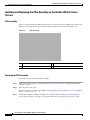
Installing or Replacing Hard Disk Drives on the E-Series Servers
The double-wide E-Series Servers can be ordered with two or three hard disk drives (HDD) or solid-state
drive (SSD) installed. The double-wide E-Series Servers support the following Redundant Array of
Independent Disks (RAID) configuration:
•
RAID 0 (data striping): Data is stored evenly in stripe blocks across all disks in the array, providing
fast throughput. There is no data redundancy, and all data is lost if any disk fails.
Cisco UCS E-Series Server Modules Hardware Installation Guide
23
Hardware Installation Guide for Cisco UCS E-Series Servers
Installing E-Series Servers in Cisco ISR G2 Routers
•
RAID 1 (disk mirroring): Data is written to two disks, where the data in both disk drives is identical
This provides complete data redundancy if one disk fails.
•
RAID 5 (disk striping with distributed parity): Data and parity information is striped and distributed
across all disks in the array with distributed parity information. RAID 5 requires three hard disk and
provides limited fault tolerance.
The double-wide E-Series Servers support adding a hot spare drive under RAID 1. If one of the disk
drives under RAID 1 fails and there is a hot spare drive installed, the system will automatically rebuild
the disk image onto the hot spare drive. The hot spare drive will replace the failed drive as the mirrored
drive under RAID 1. To maintain fault tolerance, you must install another hard disk drive.
The single-wide E-Series Servers come with two HDDs or SSDs installed. The single-wide E-Series
Servers support RAID 0 and RAID 1.
Warning
Only trained and qualified personnel should be allowed to install or replace this equipment. Statement
1030
Warning
Ultimate disposal of this product should be handled according to all national laws and regulations.
Statement 1040
Warning
No user-serviceable parts insideFCS DRAFT - CISCO CONFIDENTIALo not open. Statement 1073
Warning
This unit might have more than one power supply connection. All connections must be removed to
de-energize the unit. Statement 1028
Warning
Blank faceplates and cover panels serve three important functions: they prevent exposure to
hazardous voltages and currents inside the chassis; they contain electromagnetic interference (EMI)
that might disrupt other equipment; and they direct the flow of cooling air through the chassis. Do not
operate the system unless all cards, faceplates, front covers, and rear covers are in place. Statement
1029
To install or replace a hard disk drive on the E-Series Servers, perform the following steps:
Note
The hard disk drives should be installed in order—HDD0, HDD1, and then HDD2.
Step 1
Connect the wrist strap clip to an unpainted portion of the chassis frame to channel unwanted ESD
voltages to ground.
Step 2
Turn off power to the router.
The Cisco 3900 series routers support OIR. (See the “Online Insertion and Removal on a Cisco ISR G2
Router” section on page 22)
Step 3
Using either a number 1 Phillips screwdriver or a small flat-blade screwdriver, unscrew the captive
screws on the faceplate and remove the cover faceplate. See Figure 12 and Figure 13.
Cisco UCS E-Series Server Modules Hardware Installation Guide
24
OL-26447-01
Hardware Installation Guide for Cisco UCS E-Series Servers
Installing E-Series Servers in Cisco ISR G2 Routers
Figure 12
1
Replacing a Hard Disk Drive on the Single-Wide E-Series Server
Captive Screws
2
Hard Disk Drive Assembly
Cisco UCS E-Series Server Modules Hardware Installation Guide
25
Hardware Installation Guide for Cisco UCS E-Series Servers
Installing E-Series Servers in Cisco ISR G2 Routers
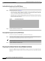
Figure 13
Step 4
Replacing a Hard Disk Drive on the Double-Wide E-Series Server
1
Hard Disk Drives
2
Hard Disk Drive Assembly
3
Cover Faceplate
4
Captive Screws on Hard Disk Drive Assembly
(Optional) If the slot is empty, use the screwdriver to loosen the screws on the bracket to remove the
bracket that is attached to the slot. See Figure 14. Go to Step 7.
Cisco UCS E-Series Server Modules Hardware Installation Guide
26
OL-26447-01
Hardware Installation Guide for Cisco UCS E-Series Servers
Installing E-Series Servers in Cisco ISR G2 Routers
Figure 14
1
Empty HDD2 Slot
Bracket
2
Captive Screws on Hard Disk Drive Assembly
Step 5
(Optional) If there is a hard disk drive, use the screwdriver to loosen the captive screws on the hard disk
drive assembly.
Step 6
(Optional) To remove the faulty hard disk, pull the handle of the hard disk drive assembly and slide out
the hard disk drive.
Step 7
Slide the new hard disk drive into the E-Series Serveruntil it clicks into place.
Step 8
Tighten the captive screws on the new hard disk drive assembly. Make sure the HDDs are firmly secure
to the carrier to avoid rattling during operating.
Step 9
Replace the faceplate.
Step 10
Restart the E-Series Server.
Step 11
Configure the new HDD as the new hotspare disk drive. Refer to the Cisco UCS E-Series Servers
Integrated Management Controller GUI Configuration Guide.
Cisco UCS E-Series Server Modules Hardware Installation Guide
27
Hardware Installation Guide for Cisco UCS E-Series Servers
Installing E-Series Servers in Cisco ISR G2 Routers
Installing and Replacing the PCIe Assembly on the Double-Wide E-Series
Servers
PCIe Assembly
Figure 15 shows the PCIe Assembly, which consists of a PCIe card, a flex assembly which connects the
PCIe slot to the motherboard, and a plastic bracket which slides over the end of the PCIe card.
Figure 15
PCIe Assembly
1
Plastic Bracket
3
PCIe Card
2
Flex Assembly
Removing the PCIe Assembly
Follow these steps to remove the PCIe Assembly:
Step 1
Connect the wrist strap clip to an unpainted portion of the chassis frame to channel unwanted ESD
voltages to ground.
Step 2
Turn off power to the router.
The Cisco 3900 series routers support OIR. (See the “Online Insertion and Removal on a Cisco ISR G2
Router” section on page 22).
Step 3
Using either a number 1 Phillips screwdriver or a small flat-blade screwdriver, unscrew the captive
screws on the faceplate. Loosen the cover faceplate and remove it. See Figure 16. Save the screws.
Cisco UCS E-Series Server Modules Hardware Installation Guide
28
OL-26447-01
Hardware Installation Guide for Cisco UCS E-Series Servers
Installing E-Series Servers in Cisco ISR G2 Routers
Figure 16
Replacing the PCIe Assembly
1
Captive Screws on the Face Plate
2
Flex Assembly Screw
3
Plastic Bracket screw
4
PCIe Assembly
Step 4
Remove the screw holding the flex assembly in place
Step 5
Remove the two screws connecting the plastic bracket to the motherboard.
Step 6
Disconnect the flex assembly connector from the motherboard.
Step 7
Remove the PCIe assembly.
Step 8
Slide the plastic bracket off the end of the PCIe card and save the bracket for future use.
Installing the PCIe Assembly
Follow these steps to install the PCIe Assembly:
Step 1
Connect the wrist strap clip to an unpainted portion of the chassis frame to channel unwanted ESD
voltages to ground.
Step 2
Turn off power to the router.
The Cisco 3900 series routers support OIR. (See the “Online Insertion and Removal on a Cisco ISR G2
Router” section on page 22)
Step 3
Connect the flex assembly onto the PCIe connector on the PCIe Card. See Figure 16.
Cisco UCS E-Series Server Modules Hardware Installation Guide
29
Hardware Installation Guide for Cisco UCS E-Series Servers
Installing E-Series Servers in Cisco ISR G2 Routers
Step 4
Slide the plastic bracket over the end of the PCIe card.
Step 5
Slide the PCIe assembly into the server module.
Step 6
Connect the flex assembly onto the motherboard. Be careful not to place any stress on the connector
contacts.
Step 7
Replace the screw that secures the flex assembly in place and tighten.
Step 8
Replace the two screws that secure the plastic bracket to the motherboard and tighten
Step 9
Tighten the captive screws on the faceplate.
Installing and Replacing DIMMS
The single-wide E-Series Servers support up to 16 GB DDR3 DIMMs and the double-wide E-Series
Servers support up to 48 GB DDR3 DIMMs.
Caution
Always wear an ESD-preventive wrist strap and ensure that it makes good contact with your skin when
you remove or install DIMMs. Connect the equipment end of the wrist strap to the metal part of the
chassis.
Caution
Handle DIMMs by the edges only. DIMMs are ESD-sensitive components and can be damaged by
mishandling.
Warning
Only trained and qualified personnel should be allowed to install or replace this equipment. Statement
1030
Warning
Ultimate disposal of this product should be handled according to all national laws and regulations.
Statement 1040
Warning
No user-serviceable parts inside. Do not open. Statement 1073
Warning
This unit might have more than one power supply connection. All connections must be removed to
de-energize the unit. Statement 1028
Warning
Blank faceplates and cover panels serve three important functions: they prevent exposure to
hazardous voltages and currents inside the chassis; they contain electromagnetic interference (EMI)
that might disrupt other equipment; and they direct the flow of cooling air through the chassis. Do not
operate the system unless all cards, faceplates, front covers, and rear covers are in place. Statement
1029
Cisco UCS E-Series Server Modules Hardware Installation Guide
30
OL-26447-01
Hardware Installation Guide for Cisco UCS E-Series Servers
Installing E-Series Servers in Cisco ISR G2 Routers
Removing a DRAM DIMM
Follow these steps to remove a DRAM DIMM:
Step 1
Connect the wrist strap clip to an unpainted portion of the chassis frame to channel unwanted ESD
voltages to ground.
Step 2
Turn off power to the router.
Alternatively, the Cisco 3900 series routers support OIR. (See the “Online Insertion and Removal on a
Cisco ISR G2 Router” section on page 22)
Step 3
Locate the DRAM DIMM on the E-Series Server.
Step 4
Pull the latches away from the DIMM at both ends to lift the DIMM slightly.
Caution
Take care not to dislodge the battery that is adjacent to the DIMM connectors.
Step 5
Pull the DIMM out of the socket as shown in Figure 17.
Figure 17
Step 6
Removing a DRAM DIMM
Place the DIMM in an antistatic bag to protect it from ESD damage.
Cisco UCS E-Series Server Modules Hardware Installation Guide
31
Hardware Installation Guide for Cisco UCS E-Series Servers
Installing E-Series Servers in Cisco ISR G2 Routers
Installing a DRAM DIMM
Follow these steps to install a DRAM DIMM:
Note
You should start installing the DIMM memory from the innermost slot to the outermost slot.
Step 1
Connect the wrist strap clip to an unpainted portion of the chassis frame to channel unwanted ESD
voltages to ground.
Step 2
Turn off power to the router.
Alternatively, the Cisco 3900 series routers support OIR. (See the “Online Insertion and Removal on a
Cisco ISR G2 Router” section on page 22)
Step 3
Note
Locate the DIMM connector.
The DIMM connectors on the double-wide E-Series Servers are positioned at an angle and the DIMM
should be inserted at approximately the same angle.
Step 4
Make sure that both latches on the DIMM connector are in the open position.
Step 5
Orient the DIMM so that the polarization notch on the DIMM lines up with the notch on the connector.
See Figure 18.
Figure 18
1
DRAM DIMM Showing Polarization Notch
Polarization notch
Step 6
Insert the DIMM into the connector.
Step 7
Carefully and firmly press the DIMM into the connector until the latches close onto the DIMM. Make
sure that both latches snaps to the closed position against the DIMM. See Figure 19.
Cisco UCS E-Series Server Modules Hardware Installation Guide
32
OL-26447-01
Hardware Installation Guide for Cisco UCS E-Series Servers
Installing E-Series Servers in Cisco ISR G2 Routers
Figure 19
Step 8
Installing a DRAM DIMM
Replace the E-Series Server.
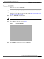
Removing the COA
In the event that you need to RMA your module, make sure that you retain the original Certificate of
Authenticity (COA) label. The COA is the label from Microsoft with the code that enables their
windows software. After you return the module, Cisco Systems cannot retrieve the COA label from the
returned module.
The COA label is attached to the inside half of a plastic pull out label tray. To remove the COA label,
cut away half of the label that contains the COA label and save it. Return the unit with the other half of
the label tray that contains the units CLEI code, Serial Number, and other important unit labels back to
Cisco Systems or your licensed reseller.
Cisco UCS E-Series Server Modules Hardware Installation Guide
33
Hardware Installation Guide for Cisco UCS E-Series Servers
Related Documentation
Figure 20
1
COA Label Placement
Plastic pull label tray
Note
The COA label from Microsoft is single layer and not foldable.
Cisco Integrated Management Controller
Cisco Integrated Management Controller (CIMC) is a separate management module built into the
motherboard. CIMC is the management service for the E-Series Servers. You can use a web-based GUI
or SSH-based CLI to access, configure, administer, and monitor the server. For more information on
CIMC, see GUI Configuration Guide for Cisco UCS E-Series Server Modules Integrated Management
Controller.
Related Documentation
For more information about configuring the Cisco UCS E-Series Servers, see he following related
documentation available for E-Series Servers:
•
Documentation Guide for Cisco UCS E-Series Servers, Release 1.0 (provides links to all documents)
•
Release Notes for Cisco UCS E-Series Servers, Release 1.0
•
Getting Started Guide for Cisco UCS E-Series Servers, Release 1.0
Cisco UCS E-Series Server Modules Hardware Installation Guide
34
OL-26447-01
Hardware Installation Guide for Cisco UCS E-Series Servers
Related Documentation
•
Cisco Network Modules, Server Modules, and Interface Cards Regulatory Compliance and Safety
Information
•
GUI Configuration Guide for Cisco UCS E-Series Servers Integrated Management Controller,
Release 1.0
•
CLI Configuration Guide for Cisco UCS E-Series Servers Integrated Management Controller,
Release 1.0
•
Troubleshooting Guide for Cisco UCS E-Series Servers
•
Open Source Used in Cisco UCS E-Series Servers, Release 1.0
For more information about installing and connecting a Cisco 2900 series and Cisco 3900 series routers,
see
http://www.cisco.com/en/US/docs/routers/access/2900/hardware/installation/guide/Hardware_Installati
on_Guide.html.
For regulatory compliance and safety information, see the Cisco Network Modules and Interface Cards
Regulatory Compliance and Safety Information document.
Cisco and the Cisco logo are trademarks or registered trademarks of Cisco and/or its affiliates in the U.S. and other countries. To view a list of
Cisco trademarks, go to this URL: www.cisco.com/go/trademarks. Third-party trademarks mentioned are the property of their respective owners. The
use of the word partner does not imply a partnership relationship between Cisco and any other company. (1110R)
Any Internet Protocol (IP) addresses and phone numbers used in this document are not intended to be actual addresses and phone numbers. Any
examples, command display output, network topology diagrams, and other figures included in the document are shown for illustrative purposes only.
Any use of actual IP addresses or phone numbers in illustrative content is unintentional and coincidental.
© 2012 Cisco Systems, Inc. All rights reserved.
Cisco UCS E-Series Server Modules Hardware Installation Guide
35
Hardware Installation Guide for Cisco UCS E-Series Servers
Related Documentation
Cisco UCS E-Series Server Modules Hardware Installation Guide
36
OL-26447-01