1
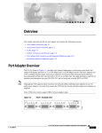
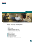
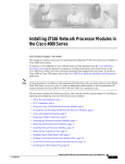
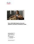
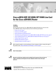
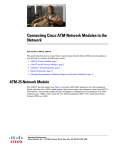
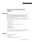
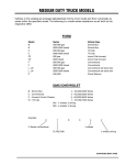
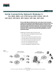
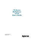
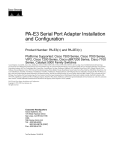
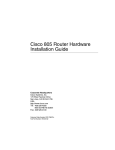
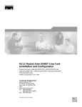
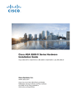
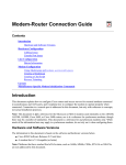
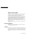
A P P E N D I X
C
Cable Specifications
This appendix provides the following cabling and pinout information for the Cisco 7100 series routers:
Note
•
Console and Auxiliary Port Cables and Pinouts, page C-1
•
Fast Ethernet Port Cables and Pinouts, page C-4
•
Cisco 7120-4T1 and Cisco 7140-8T Cables and Pinouts, page C-5
•
Cisco 7120-T3, Cisco 7120-E3, Cisco 7140-2T3, and Cisco 7140-2E3 Cables, page C-18
•
Cisco 7120-AT3, Cisco 7140-2AT3, Cisco 7120-AE3, Cisco 7140-2AE3, Cisco 7120-SMI3, and
Cisco 7140-2MM3 Cables, page C-19
This appendix specifies pinouts only for the pins used. Pins not listed in the tables in this appendix are
not connected.
Console and Auxiliary Port Cables and Pinouts
The router arrives with a console and auxiliary cable kit, which contains the cable and adapters you need
to connect a console (an ASCII terminal or PC running terminal emulation software) or modem to the
router. The console and auxiliary cable kit includes:
•
RJ-45-to-RJ-45 rollover cable
•
RJ-45-to-DB-9 female data terminal equipment (DTE) adapter labeled TERMINAL
•
RJ-45-to-DB-25 female DTE adapter labeled TERMINAL
•
RJ-45-to-DB-25 male data communications equipment (DCE) adapter labeled MODEM
Cisco 7100 Series VPN Router Installation and Configuration Guide
78-6341-03
C-1
Appendix C
Cable Specifications
Console and Auxiliary Port Cables and Pinouts
Identifying a Rollover Cable
You can identify a rollover cable by comparing the two modular ends of the cable. Holding the cables
side-by-side, with the tab at the back, the wire connected to the pin on the outside of the left plug should
be the same color as the wire connected to the pin on the outside of the right plug. (See Figure C-1.) If
your cable was purchased from Cisco Systems, pin 1 will be white on one connector, and pin 8 will be
white on the other connector (a rollover cable reverses pins 1 and 8, 2 and 7, 3 and 6, and 4 and 5).
Identifying a Rollover Cable
H5663
Figure C-1
Console Port Cables and Pinouts
Use the RJ-45-to-RJ-45 rollover cable and RJ-45-to-DB-9 female DTE adapter (labeled TERMINAL) to
connect the console port to a PC running terminal emulation software. Table C-1 lists the signals and
pinouts for the asynchronous serial console port, the RJ-45-to-RJ-45 rollover cable, and the
RJ-45-to-DB-9 female DTE adapter (labeled TERMINAL).
Table C-1
Console Port Signaling and Cabling Using a DB-9 Adapter
Console Port (DTE)
RJ-45-to-RJ-45 Rollover Cable
RJ-45-to-DB-9
Terminal Adapter
Console Device
Signal
RJ-45 Pin
RJ-45 Pin
DB-9 Pin
Signal
8
8
CTS
1
RTS
1
DTR
2
7
6
DSR
TxD
3
6
2
RxD
GND
4
5
5
GND
GND
5
4
5
GND
RxD
6
3
3
TxD
DSR
7
2
4
DTR
CTS
81
1
7
RTS
1. Pin 1 is connected internally to pin 8.
Cisco 7100 Series VPN Router Installation and Configuration Guide
C-2
78-6341-03
Appendix C
Cable Specifications
Console and Auxiliary Port Cables and Pinouts
Use the RJ-45-to-RJ-45 rollover cable and RJ-45-to-DB-25 female DTE adapter (labeled TERMINAL)
to connect the console port to a terminal. Table C-2 lists the signals and pinouts for the asynchronous
serial console port, the RJ-45-to-RJ-45 rollover cable, and the RJ-45-to-DB-25 female DTE adapter
(labeled TERMINAL).
Table C-2
Console Port Signaling and Cabling Using a DB-25 Adapter
Console Port
(DTE)1
RJ-45-to-RJ-45 Rollover Cable
RJ-45-to-DB-25
Terminal Adapter
Console Device
Signal
RJ-45 Pin
RJ-45 Pin
DB-25 Pin
Signal
8
5
CTS
2
RTS
1
DTR
2
7
6
DSR
TxD
3
6
3
RxD
GND
4
5
7
GND
GND
5
4
7
GND
RxD
6
3
2
TxD
DSR
7
2
20
DTR
1
4
RTS
CTS
8
1
1. You can use the same cabling to connect a console to the auxiliary port.
2. Pin 1 is connected internally to pin 8.
Auxiliary Port Cables and Pinouts
Use the RJ-45-to-RJ-45 rollover cable and RJ-45-to-DB-25 male DCE adapter (labeled MODEM) to
connect the auxiliary port to a modem. Table C-3 lists the signals and pinouts for the asynchronous serial
auxiliary port, the RJ-45-to-RJ-45 rollover cable, and the RJ-45-to-DB-25 male DCE adapter (labeled
MODEM).
Table C-3
Auxiliary Port Signaling and Cabling Using a DB-25 Adapter
AUX Port (DTE)
RJ-45-to-RJ-45
Rollover Cable
RJ-45-to-DB-25
Modem Adapter
Modem (DCE)
Signal
RJ-45 Pin
RJ-45 Pin
DB-25 Pin
Signal
RTS
1
8
4
RTS
DTR
2
7
20
DTR
TxD
3
6
3
TxD
GND
4
5
7
GND
GND
5
4
7
GND
RxD
6
3
2
RxD
DSR
7
2
8
DCD
CTS
8
1
5
CTS
Cisco 7100 Series VPN Router Installation and Configuration Guide
78-6341-03
C-3
Appendix C
Cable Specifications
Fast Ethernet Port Cables and Pinouts
Fast Ethernet Port Cables and Pinouts
The 10BaseT/100BaseTX Fast Ethernet ports support IEEE 802.3 and IEEE 802.3u specifications for
10-Mbps and 100-Mbps transmission over unshielded twisted-pair (UTP) cables. Each Fast Ethernet
port on the router has an RJ-45 connector to attach to Category 3 or Category 5 UTP cables.
Cisco Systems does not supply Category 3 or Category 5 UTP RJ-45 cables; these cables are available
commercially.
Use a Category 3 UTP crossover cable when connecting 10BaseT port to a hub or use a Category 3 UTP
straight-through cable when connecting to an end station.
Use a Category 5 UTP crossover cable when connecting 100BaseTX to a hub or use a Category 5 UTP
straight-through cable when connecting to an end station.
To determine the type of RJ-45 cable, examine the sequence of colored wires as follows:
•
Straight-through—Colored wires are in the same sequence at both ends of the cable.
•
Crossover—The first (far left) colored wire at one end of the cable is the third colored wire at the
other end of the cable, and the second colored wire at one end of the cable is the sixth colored wire
at the other end of the cable.
Table C-4 lists the 10BaseT pinouts and Table C-5 lists the 100BaseTX pinouts for the two Fast Ethernet
ports.
Table C-4
10BaseT RJ-45 Connector Pinouts
RJ-45 Pin
Description
1
Tx+
2
Tx–
3
Rx+
6
Rx–
Table C-5
100BaseTX RJ-45 Connector Pinouts
RJ-45 Pin
Description
1
Tx+
2
Tx–
3
Rx+
6
Rx–
Cisco 7100 Series VPN Router Installation and Configuration Guide
C-4
78-6341-03
Appendix C
Cable Specifications
Cisco 7120-4T1 and Cisco 7140-8T Cables and Pinouts
Figure C-2 shows the RJ-45 cable connectors.
RJ-45 Plug and Receptacle
87654321
RJ-45 connector
H2936
Figure C-2
Cisco 7120-4T1 and Cisco 7140-8T Cables and Pinouts
The four T1 ports on the Cisco 7120-4T1 and the eight T1 ports on the Cisco 7140-8T and adapter cables
allow a high density of interface ports, regardless of the size of the connectors typically used with each
electrical interface type. All ports use an identical 60-pin D-shell receptacle that supports all interface
types:
•
EIA/TIA-232
•
V.35
•
EIA/TIA-449
•
X.21
•
EIA-530
Each port requires a serial adapter cable, which provides the interface between the high-density serial
port and the standard connectors that are commonly used for each electrical interface type.
Note
The adapter cable determines the electrical interface type and mode of the port (DTE or DCE) to which
it is connected.
The network end of the cable is an industry-standard connector for the type of electrical interface that
the cable supports. For most interface types, the adapter cable for DTE mode uses a plug at the network
end, and the cable for DCE mode uses a receptacle at the network end. Exceptions are V.35 adapter
cables, which are available with either a V.35 plug or a receptacle for either mode, and the EIA-530
adapter cable, which is available only in DTE mode with a DB-25 plug at the network end. The mode is
labeled on the molded plastic connector shell at the ends of all cables except V.35 (which uses the
standard Winchester block-type connector instead of a molded plastic D shell).
Caution
Serial interface cables must be attached correctly, or damage to the cable plug will result. Attempting to
force a cable plug on the 60-pin receptacle can damage the plug. (See Figure C-3.)
Cisco 7100 Series VPN Router Installation and Configuration Guide
78-6341-03
C-5
Appendix C
Cable Specifications
Cisco 7120-4T1 and Cisco 7140-8T Cables and Pinouts
Figure C-3
Correct Serial Cable Orientation
Correct
Interface cable
Router port
Interface cable
Router port
22138
Incorrect, cable upside down
Table C-6 lists the available interface cable options (and product numbers) for the mode and
network-end connectors.
Table C-6
Serial Cable Product Numbers
Interface Type
Description
Product Number
EIA/TIA-232
DTE mode with a DB-25 plug
CAB-232MT=
DCE mode with a DB-25 receptacle
CAB-232FC=
DTE mode with a 37-pin D-shell plug
CAB-449MT=
DCE mode with a 37-pin D-shell receptacle
CAB-449C=
DTE mode or DCE mode with a 34-pin
Winchester-type V.35 plug
CAB-V35MT= or
CAB-V35MC=
DTE mode or DCE mode with a 34-pin
Winchester-type V.35 receptacle
CAB-V35FT= or
CAB-V35FC=
Male DB-60 plug on the router end and a male
DB-34 shielded plug on the network end
CAB-V35MTS=
DTE mode with a DB-15 plug
CAB-X21MT=
DCE mode with a DB-25 receptacle
CAB-X21FC=
DTE mode with a DB-25 plug
CAB-530MT=
EIA/TIA-449
V.35
X.21
EIA-530
Cisco 7100 Series VPN Router Installation and Configuration Guide
C-6
78-6341-03
Appendix C
Cable Specifications
Cisco 7120-4T1 and Cisco 7140-8T Cables and Pinouts
Figure C-4 shows the supported serial cables.
Figure C-4
T1 Serial Cables
23975
Router connections
EIA/TIA-449
EIA/TIA-232
V.35
X.21
EIA-530
Network connections at the modem or CSU/DSU
Metric (M3) thumbscrews are included with each cable to allow connections to devices that use metric
hardware. Because the T1 ports use a special, high-density port that requires special adapter cables for
each electrical interface type, we recommend that you obtain serial interface cables from the factory.
Serial signals can travel a limited distance at any given bit rate; generally, the slower the baud rate, the
greater the distance. All serial signals are subject to distance limits beyond which a signal degrades
significantly or is completely lost.
Table C-7 lists the recommended (standard) maximum speeds and distances for each serial interface
type. The recommended maximum rate for V.35 is 2.048 Mbps.
Table C-7
Recommended (Standard) Maximum Speeds and Distances for Serial Interfaces
EIA/TIA-232 Distances
EIA/TIA-449, X.21, V.35, EIA-530 Distances
Rate (bps)
Feet
Meters
Feet
Meters
2400
200
60
4,100
1,250
4800
100
30
2,050
625
9600
50
15
1,025
312
19200
25
7.6
513
156
38400
12
3.7
256
78
Cisco 7100 Series VPN Router Installation and Configuration Guide
78-6341-03
C-7
Appendix C
Cable Specifications
Cisco 7120-4T1 and Cisco 7140-8T Cables and Pinouts
Table C-7
Recommended (Standard) Maximum Speeds and Distances for Serial Interfaces (continued)
EIA/TIA-232 Distances
EIA/TIA-449, X.21, V.35, EIA-530 Distances
56000
8.6
2.6
102
31
1544000 (T1)
–
–
50
15
Balanced drivers allow EIA/TIA-449 signals to travel greater distances than EIA/TIA-232 signals. The
recommended distance limits for EIA/TIA-449 shown in Table C-7 are also valid for V.35, X.21, and
EIA-530. EIA/TIA-449 and EIA-530 support 2.048-Mbps rates, and V.35 supports 2.048-Mbps rates
without any problems; we do not recommend exceeding published specifications for transmission speed
versus distance. Do so at your own risk.
EIA/TIA-232 Connections
The router end of all EIA/TIA-232 adapter cables is a high-density 60-pin plug. The network end of the
adapter cable is a standard 25-pin D-shell connector (known as a DB-25) that is commonly used for
EIA/TIA-232 connections. Figure C-5 shows the connectors at the network end of the adapter cable.
Do not use the Cisco Systems-provided EIA/TIA-232 adapter cable product number CAB-232MT= to
connect a T1 interface that is configured for DTE mode directly to an NEC - NEXTSTAR 1E model
C4969 MD/SAC unit interface that is configured for DCE mode. Doing so will keep transmit and receive
data signals from being properly exchanged between the two interfaces.
Instead, you must connect an additional, intermediate adapter cable—with standard EIA/TIA-232
DB-25 connectors at both ends—from the network end of product number CAB-232MT= to the standard
EIA/TIA-232 DB-25 connector (the DCE interface) on the NEC - NEXTSTAR 1E model C4969
MD/SAC unit. Cisco Systems does not provide this additional cable; however, its signals and pin
assignments are listed in Table C-8.
You can use the Cisco Systems-provided EIA/TIA-232 adapter cable product number CAB-232FC= to
connect a T1 interface that is configured for DCE mode directly to an NEC - NEXTSTAR 1E model
C4969 MD/SAC unit interface that is configured for DTE mode. This cable’s pin assignments are listed
in Table C-9.
Figure C-5
EIA/TIA-232 Adapter Cable Connectors
DCE
Table C-8
H1343a
DTE
EIA/TIA-232 Adapter Cable Signals (DTE)
DTE Cable (CAB-232MT=)
Router End, HD1
60-Position Plug
Signal
Network End,
DB-25 Plug
Pin
Pin
Signal
Cisco 7100 Series VPN Router Installation and Configuration Guide
C-8
78-6341-03
Appendix C
Cable Specifications
Cisco 7120-4T1 and Cisco 7140-8T Cables and Pinouts
Table C-8
EIA/TIA-232 Adapter Cable Signals (DTE) (continued)
DTE Cable (CAB-232MT=)
Shield ground
46
–
1
Shield ground
TxD/RxD
41
—>
2
TxD
RxD/TxD
36
<—
3
RxD
RTS/CTS
42
—>
4
RTS
CTS/RTS
35
<—
5
CTS
DSR/DTR
34
<—
6
DSR
Circuit ground
45
–
7
Circuit ground
DCD/LL
33
<—
8
DCD
TxC/NIL
37
<—
15
TxC
RxC/TxCE
38
<—
17
RxC
LL/DCD
44
—>
18
LTST
DTR/DSR
43
—>
20
DTR
TxCE/TxC
39
—>
24
TxCE
Mode 0
Ground
Mode_DCE
50
51
52
–
–
Shorting group
1. HD = high-density.
Table C-9
EIA/TIA-232 Adapter Cable Signals (DCE)
DCE Cable (CAB-232FC=)
Router End, HD1
60-Position Plug
Network End,
DB-25 Receptacle
Signal
Pin
Pin
Signal
Shield ground
46
–
1
Shield ground
RxD/TxD
36
<—
2
TxD
TxD/RxD
41
—>
3
RxD
CTS/RTS
35
<—
4
RTS
RTS/CTS
42
—>
5
CTS
DTR/DSR
43
—>
6
DSR
Circuit ground
45
–
7
Circuit ground
LL/DCD
44
—>
8
DCD
TxCE/TxC
39
—>
15
TxC
NIL/RxC
40
—>
17
RxC
DCD/LL
33
<—
18
LTST
DSR/DTR
34
<—
20
DTR
Cisco 7100 Series VPN Router Installation and Configuration Guide
78-6341-03
C-9
Appendix C
Cable Specifications
Cisco 7120-4T1 and Cisco 7140-8T Cables and Pinouts
Table C-9
EIA/TIA-232 Adapter Cable Signals (DCE) (continued)
DCE Cable (CAB-232FC=)
RxC/TxCE
38
<—
24
TxCE
Mode 0
Ground
50
51
–
–
Shorting group
1. HD = high-density.
EIA/TIA-449 Connections
The router end of all EIA/TIA-449 adapter cables is a high-density 60-pin plug. The network end of the
adapter cable provides a standard 37-pin D-shell connector, which is commonly used for EIA/TIA-449
connections. Figure C-6 shows the connectors at the network end of the adapter cable. EIA/TIA-449
cables are available as either DTE (DB-37 plug) or DCE (DB-37 receptacle). See Table C-10 and
Table C-11 for pinouts.
Figure C-6
EIA/TIA-449 Adapter Cable Connectors
DCE
H1344a
DTE
Table C-10 EIA/TIA-449 Adapter Cable Signals (DTE)
DTE Cable (CAB-449MT=)
Router End, HD1
60-Position Plug
Network End,
DB-37 Plug
Signal
Pin
Pin
Signal
Shield ground
46
–
1
Shield ground
TxD/RxD+
11
—>
4
SD+
TxD/RxD–
12
—>
22
SD–
TxC/RxC+
24
<—
5
ST+
TxC/RxC–
23
<—
23
ST–
RxD/TxD+
28
<—
6
RD+
RxD/TxD–
27
<—
24
RD–
RTS/CTS+
9
—>
7
RS+
RTS/CTS–
10
—>
25
RS–
RxC/TxCE+
26
<—
8
RT+
RxC/TxCE–
25
<—
26
RT–
CTS/RTS+
1
<—
9
CS+
CTS/RTS–
2
<—
27
CS–
Cisco 7100 Series VPN Router Installation and Configuration Guide
C-10
78-6341-03
Appendix C
Cable Specifications
Cisco 7120-4T1 and Cisco 7140-8T Cables and Pinouts
Table C-10 EIA/TIA-449 Adapter Cable Signals (DTE) (continued)
DTE Cable (CAB-449MT=)
LL/DCD
44
—>
10
LL
Circuit ground
45
–
37
SC
DSR/DTR+
3
<—
11
ON+
DSR/DTR–
4
<—
29
ON–
DTR/DSR+
7
—>
12
TR+
DTR/DSR–
8
—>
30
TR–
DCD/DCD+
5
<—
13
RR+
DCD/DCD–
6
<—
31
RR–
TxCE/TxC+
13
—>
17
TT+
TxCE/TxC–
14
—>
35
TT–
Circuit ground
15
–
19
SG
Circuit ground
16
–
20
RC
Mode 1
Ground
49
48
–
–
Shorting group
Ground
Mode_DCE
51
52
–
–
Shorting group
1. HD = high-density.
Table C-11 EIA/TIA-449 Adapter Cable Signals (DCE)
DCE Cable (CAB-449C=)
Router End, HD1
60-Position Plug
Network End,
DB-37 Receptacle
Signal
Pin
Pin
Signal
Shield ground
46
–
1
Shield ground
RxD/TxD+
28
<—
4
SD+
RxD/TxD–
27
<—
22
SD–
TxCE/TxC+
13
—>
5
ST+
TxCE/TxC–
14
—>
23
ST–
TxD/RxD+
11
—>
6
RD+
TxD/RxD–
12
—>
24
RD–
CTS/RTS+
1
<—
7
RS+
CTS/RTS–
2
<—
25
RS–
TxC/RxC+
24
—>
8
RT+
TxC/RxC–
23
—>
26
RT–
RTS/CTS+
9
—>
9
CS+
RTS/CTS–
10
—>
27
CS–
Cisco 7100 Series VPN Router Installation and Configuration Guide
78-6341-03
C-11
Appendix C
Cable Specifications
Cisco 7120-4T1 and Cisco 7140-8T Cables and Pinouts
Table C-11 EIA/TIA-449 Adapter Cable Signals (DCE) (continued)
DCE Cable (CAB-449C=)
NIL/LL
29
—>
10
LL
Circuit ground
30
–
37
SC
DTR/DSR+
7
—>
11
ON+
DTR/DSR–
8
—>
29
ON–
DSR/DTR+
3
<—
12
TR+
DSR/DTR–
4
<—
30
TR–
DCD/DCD+
5
—>
13
RR+
DCD/DCD–
6
—>
31
RR–
RxC/TxCE+
26
<—
17
TT+
RxC/TxCE–
25
<—
35
TT–
Circuit ground
15
–
19
SG
Circuit ground
16
–
20
RC
Mode 1
Ground
49
48
–
–
Shorting group
1. HD = high-density.
V.35 Connections
The router end of all V.35 adapter cables is a high-density 60-pin plug. The network end of the adapter
cable provides a standard 34-pin Winchester-type connector commonly used for V.35 connections.
Figure C-7 shows the connectors at the network end of the V.35 adapter cable. V.35 cables are available
with a standard V.35 plug for DTE mode (CAB-V35MT=) or a V.35 receptacle for DCE mode
(CAB-V35FC=). See Table C-12 and Table C-13 for pinouts.
Figure C-7
V.35 Adapter Cable Connectors
DCE
H1616a
DTE
Also available, but not shown in Figure C-7, are CAB-V35MC=, a V.35 cable with a plug on the network
end for DCE mode, and CAB-V35FT=, a V.35 cable with a receptacle on the network end for DTE mode.
These cables are used for connecting V.35-equipped systems back to back.
Cisco 7100 Series VPN Router Installation and Configuration Guide
C-12
78-6341-03
Appendix C
Cable Specifications
Cisco 7120-4T1 and Cisco 7140-8T Cables and Pinouts
Table C-12 V.35 Adapter Cable Signals (DTE)
DTE Cable (CAB-V35FT= or CAB-V35MT=)
Router End, HD1
60-Position Plug
Network End, 34-Position Plug
Signal
Pin
Pin
Signal
Shield ground
46
–
A
Frame ground
Circuit ground
45
–
B
Circuit ground
RTS/CTS
42
—>
C
RTS
CTS/RTS
35
<—
D
CTS
DSR/DTR
34
<—
E
DSR
DCD/LL
33
<—
F
RLSD
DTR/DSR
43
—>
H
DTR
LL/DCD
44
—>
K
LT
TxD/RxD+
18
—>
P
SD+
TxD/RxD–
17
—>
S
SD–
RxD/TxD+
28
<—
R
RD+
RxD/TxD–
27
<—
T
RD–
TxCE/TxC+
20
—>
U
SCTE+
TxCE/TxC–
19
—>
W
SCTE–
RxC/TxCE+
26
<—
V
SCR+
RxC/TxCE–
25
<—
X
SCR–
TxC/RxC+
24
<—
Y
SCT+
TxC/RxC–
23
<—
AA
SCT–
Mode 1
Ground
49
48
–
–
Shorting group
Mode 0
Ground
Mode_DCE
50
51
52
–
–
Shorting group
TxC/NIL
RxC/TxCE
RxC/TxD
Ground
53
54
55
56
–
–
Shorting group
1. HD = high-density.
Table C-13 V.35 Adapter Cable Signals (DCE)
DCE Cable (CAB-V35FC= or CAB-V35MC=)
Router End, HD1
60-Position Plug
Signal
Network End, 34-Position
Receptacle
Pin
Pin
Signal
Cisco 7100 Series VPN Router Installation and Configuration Guide
78-6341-03
C-13
Appendix C
Cable Specifications
Cisco 7120-4T1 and Cisco 7140-8T Cables and Pinouts
Table C-13 V.35 Adapter Cable Signals (DCE) (continued)
DCE Cable (CAB-V35FC= or CAB-V35MC=)
Shield ground
46
–
A
Frame ground
Circuit ground
45
–
B
Circuit ground
CTS/RTS
35
<—
C
RTS
RTS/CTS
42
—>
D
CTS
DTR/DSR
43
—>
E
DSR
LL/DCD
44
—>
F
RLSD
DSR/DTR
34
<—
H
DTR
DCD/LL
33
<—
K
LT
RxD/TxD+
28
<—
P
SD+
RxD/TxD–
27
<—
S
SD–
TxD/RxD+
18
—>
R
RD+
TxD/RxD–
17
—>
T
RD–
RxC/TxCE+
26
<—
U
SCTE+
RxC/TxCE–
25
<—
W
SCTE–
NIL/RxC+
22
—>
V
SCR+
NIL/RxC–
21
—>
X
SCR–
TxCE/TxC+
20
—>
Y
SCT+
TxCE/TxC–
19
—>
AA
SCT–
Mode 1
Ground
49
48
–
–
Shorting group
Mode 0
Ground
50
51
–
–
Shorting group
TxC/NIL
RxC/TxCE
RxC/TxD
Ground
53
54
55
56
–
–
Shorting group
1. HD = high-density.
Cisco 7100 Series VPN Router Installation and Configuration Guide
C-14
78-6341-03
Appendix C
Cable Specifications
Cisco 7120-4T1 and Cisco 7140-8T Cables and Pinouts
X.21 Connections
The router end of all X.21 adapter cables is a high-density 60-pin plug. The network end of the adapter
cable is a standard DB-15 connector. Figure C-8 shows the connectors at the network end of the X.21
adapter cable. X.21 cables are available as either DTE (DB-15 plug) or DCE (DB-15 receptacle). See
Table C-14 and Table C-15 for pinouts.
Figure C-8
X.21 Adapter Cable Connectors
DTE
15
H1346a
1
8
DCE
9
Table C-14 X.21 Adapter Cable Signals (DTE)
DTE Cable (CAB-X21MT=)
Router End, HD1
60-Position Plug
Network End,
DB-15 Plug
Signal
Pin
Pin
Signal
Shield ground
46
–
1
Shield ground
TxD/RxD+
11
—>
2
Transmit+
TxD/RxD–
12
—>
9
Transmit–
RTS/CTS+
9
—>
3
Control+
RTS/CTS –
10
—>
10
Control–
RxD/TxD+
28
<—
4
Receive+
RxD/TxD–
27
<—
11
Receive–
CTS/RTS+
1
<—
5
Indication+
CTS/RTS –
2
<—
12
Indication–
RxC/TxCE+
26
<—
6
Timing+
RxC/TxCE–
25
<—
13
Timing–
Circuit ground
15
–
8
Circuit ground
Ground
Mode_2
48
47
–
–
Shorting group
Ground
Mode_DCE
51
52
–
–
Shorting group
1. HD = high-density.
Cisco 7100 Series VPN Router Installation and Configuration Guide
78-6341-03
C-15
Appendix C
Cable Specifications
Cisco 7120-4T1 and Cisco 7140-8T Cables and Pinouts
Table C-15 X.21 Adapter Cable Signals (DCE)
DCE Cable (CAB-X21FC=)
Router End, HD1
60-Position Plug
Network End,
DB-15 Receptacle
Signal
Pin
Pin
Signal
Shield ground
46
–
1
Shield ground
RxD/TxD+
11
—>
2
Transmit+
RxD/TxD–
12
—>
9
Transmit–
CTS/RTS+
9
—>
3
Control+
CTS/RTS –
10
—>
10
Control–
TxD/RxD+
28
<—
4
Receive+
TxD/RxD–
27
<—
11
Receive–
RTS/CTS+
1
<—
5
Indication+
RTS/CTS–
2
<—
12
Indication–
TxC/RxC+
26
<—
6
Timing+
TxC/RxC –
25
<—
13
Timing–
Circuit ground
15
–
8
Circuit ground
Ground
Mode_2
48
47
–
–
Shorting group
Ground
Mode_DCE
51
52
–
–
–
1. HD = high-density.
EIA-530 Connections
The EIA-530 adapter cable is available in DTE mode only. The router end of the EIA-530 adapter cable
is a high-density 60-pin plug. The network end of the adapter cable is a standard DB-25 plug commonly
used for EIA/TIA-232 connections. Figure C-9 shows the DB-25 connector at the network end of the
adapter cable.
EIA-530 Adapter Cable Connector
H1615a
Figure C-9
DTE
Table C-16 EIA-530 DTE Adapter Cable Signals (CAB-530MT=)
Router End, HD1
60-Position Plug
Network End,
DB-25 Plug
Signal
Pin
Shield ground
46
–
Pin
Signal
1
Shield ground
Cisco 7100 Series VPN Router Installation and Configuration Guide
C-16
78-6341-03
Appendix C
Cable Specifications
Cisco 7120-4T1 and Cisco 7140-8T Cables and Pinouts
Table C-16 EIA-530 DTE Adapter Cable Signals (CAB-530MT=)
Router End, HD1
60-Position Plug
Network End,
DB-25 Plug
TxD/RxD+
11
—>
2
TxD+
TxD/RxD–
12
—>
14
TxD–
RxD/TxD+
28
<—
3
RxD+
RxD/TxD–
27
<—
16
RxC–
RTS/CTS+
9
—>
4
RTS+
RTS/CTS–
10
—>
19
RTS–
CTS/RTS+
1
<—
5
CTS+
CTS/RTS–
2
<—
13
CTS–
DSR/DTR+
3
<—
6
DSR+
DSR/DTR–
4
<—
22
DSR–
DCD/DCD+
5
<—
8
DCD+
DCD/DCD–
6
<—
10
DCD–
TxC/RxC+
24
<—
15
TxC+
TxC/RxC–
23
<—
12
TxC–
RxC/TxCE+
26
<—
17
RxC+
RxC/TxCE–
25
<—
9
RxC–
LL/DCD
44
—>
18
LL
Circuit ground
45
–
7
Circuit ground
DTR/DSR+
7
—>
20
DTR+
DTR/DSR–
8
—>
23
DTR–
TxCE/TxC+
13
—>
24
TxCE+
TxCE/TxC–
14
—>
11
TxCE–
Mode_1
Ground
Mode_2
49
48
47
–
–
Shorting group
Ground
Mode_DCE
51
52
–
–
Shorting group
1. HD = high-density.
Cisco 7100 Series VPN Router Installation and Configuration Guide
78-6341-03
C-17
Appendix C
Cable Specifications
Cisco 7120-T3, Cisco 7120-E3, Cisco 7140-2T3, and Cisco 7140-2E3 Cables
Cisco 7120-T3, Cisco 7120-E3, Cisco 7140-2T3, and
Cisco 7140-2E3 Cables
The T3 or E3 serial interface cable on the Cisco 7120 and Cisco 7140 series, which is a 75-ohm coaxial
cable, is used to connect your router to a T3 or E3 serial network. Serial cables conform to EIA/TIA-612
and EIA/TIA-613 specifications. The serial ports are considered to be DTE devices.
The T3 or E3 serial port has two connectors (receive and transmit) where you connect the Cisco 75-ohm
coaxial cable. The 75-ohm coaxial cable (Cisco product number CAB-ATM-DS3/E3), is available only
from Cisco Systems; it is not available from outside commercial cable vendors.
Figure C-10 shows the Cisco 75-ohm coaxial cable, which is available in 10-foot (3.05-meter) lengths
only. The typical maximum distance between stations for T3 or E3 transmissions is 1300 feet (396
meters).
Note
For E3 (75-ohm) connections, you must have ferrite beads on the 75-ohm coaxial cable and
electromagnetic interference (EMI) decoupling clips on the receiver end of the cable (see Figure C-10)
if compliance with European certification standards for emission control is required (EN55022/CISPR22
Class B for radiated emission levels).
Figure C-10 T3 and E3 Serial Port Adapter Cables
75-ohm coaxial cabling
BNC plug
I
RCVR
EN
XMTR
RCLK FERF RL RCLK FERF
RL
RCVR
BNC plug
22139
5
XMTR
AIS OOF LL AIS OOF LL
EMI decoupler clip
Ferrite bead
To T3 network
equipment
The T3 and E3 ports support several types of integrated data service units (DSUs). Table C-17 lists the
features supported.
Table C-17 Feature Compatibilities of T3 and E3 Serial Port DSUs
Device
Full Rate
Scrambling
Subrate
MDL1
Yes
Yes
Yes
No
T3 DSU
DL3100
Kentrox
Yes
Yes
Larscom
Yes
Yes
2
Yes
Yes
2
No
No
E3 DSU
Cisco 7100 Series VPN Router Installation and Configuration Guide
C-18
78-6341-03
Appendix C
Cable Specifications
Cisco 7120-AT3, Cisco 7140-2AT3, Cisco 7120-AE3, Cisco 7140-2AE3, Cisco 7120-SMI3, and Cisco 7140-2MM3 Cables
Table C-17 Feature Compatibilities of T3 and E3 Serial Port DSUs (continued)
Device
Full Rate
Scrambling
Subrate
MDL1
DL3100E
Yes
No3
Yes3
No
2
No
Kentrox
Yes
Yes
2
Yes
1. MDL = Maintenance Digital Link.
2. T3 and E3 serial ports support either scrambling or Kentrox subrate, not both at the same time.
3. DL3100E does not support scrambling. However, the E3 serial port can turn on scrambling in DSU mode 0 for connecting
to another E3 serial port. The E3 serial port supports either scrambling (in mode 0) or DL3100E subrate, not both at the
same time.
Cisco 7120-AT3, Cisco 7140-2AT3, Cisco 7120-AE3,
Cisco 7140-2AE3, Cisco 7120-SMI3, and Cisco 7140-2MM3
Cables
The AT3, AE3, MM3 (OC-3c/STM-1 multimode), and SMI3 (OC-3c/STM-1 single-mode intermediate
reach) interfaces in Cisco 7120 series and Cisco 7140 series routers are full duplex. You must use the
appropriate ATM interface cable to connect the interface with an external ATM network. These
interfaces are considered DTE devices.
Table C-18 summarizes the interface types, connectors, and cables.
Table C-18 AT3, AE3, MM3, and SMI3 Connector Types and Cables
Note
Interface
Rate
(Mbps)
Connector
Type
ITU-T G.957
Cable Type Standard
Bellcore
GR-253
Standard
Wavelength
Maximum
Distance
AT3
44.736
BNC
Coaxial
–
–
–
450 ft
(137.2 m)
AE3
34.368
BNC
Coaxial
–
–
–
1250 ft
(381 m)
MM3
155.52
SC
62.5/125
Intra-office
microns
STM-1 I-1
multimode
SMI3
155.52
SC
Intermediat 1310 nm
9 microns Short-haul
single mod STM-1 S-1.1 e reach
e
OC3
Short reach 1310 nm
OC3
1.2 mi
(2 km)
9.3 mi
(15 km)
The ATM port is considered a DTE device.
Cisco 7100 Series VPN Router Installation and Configuration Guide
78-6341-03
C-19
Appendix C
Cable Specifications
Cisco 7120-AT3, Cisco 7140-2AT3, Cisco 7120-AE3, Cisco 7140-2AE3, Cisco 7120-SMI3, and Cisco 7140-2MM3 Cables
AT3 and AE3 Cables and Receptacles
The AT3 and AE3 interfaces provide an interface to ATM switching fabrics for the bidirectional
transmission and reception of data at rates of up to 45 Mbps (for T3) and 34 Mbps (for E3).
The AT3 and AE3 interfaces use a 75-ohm coaxial interface cable to connect your router to an ATM T3
or E3 network. The AT3 and AE3 cables (see Figure C-11) conform to EIA/TIA-612 and EIA/TIA-613
specifications. The AT3 and AE3 ports are considered DTE devices.
Figure C-11 AT3 and AE3 Cables
75-ohm coaxial cabling
I
DS3
EN
RX
TX
RX
CEL CAR ALM
BNC plug
22878
BNC plug
5
Ferrite bead
To ATM network
equipment
AT3 or AE3 ports consist of two connectors, transmit and receive. The 75-ohm coaxial cable (Cisco
product number CAB-ATM-DS3/E3) is available only from Cisco Systems; it is not available from
outside commercial cable vendors.
The Cisco 75-ohm coaxial cable is available only in 10-foot (3.05-meter) lengths. The typical maximum
distance between stations for T3 and E3 transmissions is 1300 feet (396 meters).
Note
To ensure compliance with EMI and European certification standards for emission control
(EN55022/CISPR22 Class B for radiated emission levels), the transmit and receive cables should be tied
together along their entire length, and ferrite beads should be installed on each cable near the transmit
and receive connectors.
Cisco 7100 Series VPN Router Installation and Configuration Guide
C-20
78-6341-03
Appendix C
Cable Specifications
Cisco 7120-AT3, Cisco 7140-2AT3, Cisco 7120-AE3, Cisco 7140-2AE3, Cisco 7120-SMI3, and Cisco 7140-2MM3 Cables
MM3 and SMI3 Cables and Receptacles
The MM3 (OC-3c/STM-1 multimode) and SMI3 (OC-3c/STM-1 single-mode intermediate reach)
interfaces provides an interface to ATM switching fabrics for transmitting and receiving data at rates of
up to 155 Mbps bidirectionally. The MME and SMI3 interfaces connect to SONET/SDH, 155-Mbps
multimode or single-mode optical fiber.
For SONET/SDH multimode and SONET/SDH single-mode connections, use one duplex SC connector
(see Figure C-12) or two simplex SC connectors (see Figure C-13). The simplex and duplex SC
connectors are shipped with removable dust covers on each connector.
H2214
Figure C-12 Duplex SC Connector
H2399
Figure C-13 Simplex SC Connector
An OC-3 ATM interface cable, which is used to connect your router to an external DSU (an ATM
network), is available for use with the MM3 and SMI3 interfaces. Cables can be obtained from an outside
cable vendor.
Single-mode and multimode cables should perform to the specifications listed in Table C-19.
Table C-19 Fiber-Optic Cable Specifications
Standard
Maximum Path Length
Cabling
ISO/IEC 9314-3
1.2 miles (2 km) all cables in a 62.5-micron core with an
connection, end to end
optical loss of 0–9 dB, or
50-micron core with an optical
loss of 7 dB
IEC 793-2
24.8 mi (40 km) for SML1 and 9-micron core
9.3 mi (15 km) for SMI2
ANSI/TIA/EIA-492CAAA
24.8 mi (40 km) for SML and
9.3 mi (15 km) for SMI
9-micron core
1. SML = single-mode long reach.
2. SMI = single-mode intermediate reach.
Cisco 7100 Series VPN Router Installation and Configuration Guide
78-6341-03
C-21
Appendix C
Cable Specifications
Cisco 7120-AT3, Cisco 7140-2AT3, Cisco 7120-AE3, Cisco 7140-2AE3, Cisco 7120-SMI3, and Cisco 7140-2MM3 Cables
Note
A single fiber link should not mix 62.5- and 50-micron cable.
Fiber-Optic Transmission Specifications
The following sections describe the SONET specifications for fiber-optic transmissions, define the
power budget, and help you approximate the power margin for multimode and single-mode
transmissions.
For more information on determining attenuation and power budget, see the following publications:
•
T1E1.2/92-020R2 ANSI, the Draft American National Standard for Telecommunications entitled
Broadband ISDN Customer Installation Interfaces: Physical Layer Specification.
•
Power Margin Analysis, AT&T Technical Note, TN89-004LWP, May 1989
SONET Distance Limitations
The SONET specification for fiber-optic transmission defines two types of fiber: single mode and
multimode. Modes can be thought of as bundles of light rays entering the fiber at a particular angle.
Single-mode fiber allows only one mode of light to propagate through the fiber, whereas multimode fiber
allows multiple modes of light to propagate through the fiber. Because multiple modes of light
propagating through the fiber travel different distances depending on the entry angles, causing them to
arrive at the destination at different times (a phenomenon called modal dispersion), single-mode fiber is
capable of higher bandwidth and greater cable run distances than multimode fiber.
The typical maximum distances for single-mode and multimode transmissions, as defined by SONET,
are in Table C-20. If the distance between two connected stations is greater than this maximum distance,
significant signal loss can result, making transmission unreliable.
Table C-20 SONET Maximum Fiber-Optic Transmission Distances
Transceiver Type
Maximum Distance between Stations1
Single-mode long reach (SML)
Up to 24.8 miles (40 kilometers)
Single-mode intermediate reach (SMI)
Up to 9.3 miles (15 kilometers)
Multimode (MM)
Up to 1.2 miles (2 kilometers)
1. Table C-20 gives typical results. Use the power budget calculations described in the following sections to determine the
actual distances.
Power Budget
To design an efficient optical data link, evaluate the power budget. The power budget is the amount of
light available to overcome attenuation in the optical link and to exceed the minimum power that the
receiver requires to operate within its specifications. Proper operation of an optical data link depends on
modulated light reaching the receiver with enough power to be correctly demodulated.
Attenuation, caused by the passive media components (cables, cable splices, and connectors), is common
to both multimode and single-mode transmission.
The following variables reduce the power of the signal (light) transmitted to the receiver in multimode
transmission:
Cisco 7100 Series VPN Router Installation and Configuration Guide
C-22
78-6341-03
Appendix C
Cable Specifications
Cisco 7120-AT3, Cisco 7140-2AT3, Cisco 7120-AE3, Cisco 7140-2AE3, Cisco 7120-SMI3, and Cisco 7140-2MM3 Cables
•
Chromatic dispersion—Spreading of the signal in time because of the different speeds of light
wavelengths
•
Modal dispersion—Spreading of the signal in time because of the different propagation modes in
the fiber
Attenuation is significantly lower for optical fiber than for other media. For multimode transmission,
chromatic and modal dispersion reduce the available power of the system by the combined dispersion
penalty (dB). The power lost over the data link is the sum of the component, dispersion, and modal
losses.
Table C-21 lists the factors of attenuation and dispersion for typical fiber-optic cable.
Table C-21 Typical Fiber-Optic Link Attenuation and Dispersion Limits
Limits
Single-mode
Multimode
Attenuation
0.5 dB/km
1.0 dB/km
Dispersion
No limit
500 MHz/km1
1. The product of bandwidth and distance must be less than 500 MHz/km.
Approximating the MM3 and SMI3 Port Power Margin
The LED used for a multimode transmission light source creates multiple propagation paths of light,
each with a different path length and time requirement to cross the optical fiber, causing signal
dispersion (smear). Higher-order mode loss (HOL) results from light from the LED entering the fiber
and being radiated into the fiber cladding. A worst-case estimate of power margin (PM) for multimode
transmissions assumes minimum transmitter power (PT), maximum link loss (LL), and minimum
receiver sensitivity (PR). The worst-case analysis provides a margin of error; not all of the parts of an
actual system will operate at the worst-case levels.
The power budget (PB) is the maximum possible amount of power transmitted. The following equation
lists the calculation of the power budget:
PB = PT – PR
PB = –20 dBm – (–30 dBm)
PB = 10 dB
The power margin calculation is derived from the power budget minus the link loss, as follows:
PM = PB – LL
If the power margin is positive, the link will work.
Table C-22 lists the factors that contribute to link loss and the estimate of the link loss value attributable
to those factors.
Table C-22 Link Loss Factors and Values
Link Loss Factor
Estimate of Link Loss Value
Higher-order mode losses
0.5 dB
Clock recovery module
1 dB
Modal and chromatic dispersion
Dependent on fiber and wavelength used
Connector
0.5 dB
Cisco 7100 Series VPN Router Installation and Configuration Guide
78-6341-03
C-23
Appendix C
Cable Specifications
Cisco 7120-AT3, Cisco 7140-2AT3, Cisco 7120-AE3, Cisco 7140-2AE3, Cisco 7120-SMI3, and Cisco 7140-2MM3 Cables
Table C-22 Link Loss Factors and Values (continued)
Link Loss Factor
Estimate of Link Loss Value
Splice
0.5 dB
Fiber attenuation
1 dB/km
After calculating the power budget minus the data link loss, the result should be greater than zero.
Circuits whose results are less than zero may have insufficient power to operate the receiver.
The SONET specification requires that the signal must meet the worst-case parameters listed
in Table C-23.
Table C-23 MM3 and SMI3 Port SONET Signal Requirements
Variable
Single Mode (SML)
Single Mode (SMI) Multimode
PT
–5 dBm
–15 dBm
–20 dBm
PR
–34 dBm
–31 dBm
–30 dBm
PB
29 dBm
16 dB
10 dB
Multimode Power Budget Example with Sufficient Power for Transmission
The following is an example multimode power budget calculated based on the following variables:
•
Length of multimode link = 3 kilometers (km)
•
Four connectors
•
Three splices
•
Higher-order mode loss (HOL)
•
Clock recovery module (CRM)
Estimate the power budget as follows:
PB = 10 dB – 3 km (1.0 dB/km) – 4 (0.5 dB) – 3 (0.5 dB) – 0.5 dB (HOL) – 1 dB (CRM)
PB = 10 dB – 3 dB – 2 dB – 1.5 dB – 0.5 dB – 1 dB
PB = 2 dB
The positive value of 2 dB indicates that this link would have sufficient power for transmission.
Multimode Power Budget Example of Dispersion Limit
Following is an example with the same parameters as the previous example, but with a multimode link
distance of 4 km:
PB = 10 dB – 4 km (1.0 dB/km) – 4 (0.5 dB) – 3 (0.5 dB) – 0.5 dB (HOL) – 1 dB (CRM)
PB = 10 dB – 4 dB – 2 dB – 1.5 dB – 0.5 dB – 1 dB
PB = 1 dB
The value of 1 dB indicates that this link would have sufficient power for transmission. But, due to the
dispersion limit on the link (4 km x 155.52 MHz > 500 MHz/km), this link would not work with
multimode fiber. In this case, single-mode fiber would be the better choice.
Cisco 7100 Series VPN Router Installation and Configuration Guide
C-24
78-6341-03
Appendix C
Cable Specifications
Cisco 7120-AT3, Cisco 7140-2AT3, Cisco 7120-AE3, Cisco 7140-2AE3, Cisco 7120-SMI3, and Cisco 7140-2MM3 Cables
Single-Mode Transmission
The single-mode signal source is an injection laser diode. Single-mode transmission is useful for longer
distances, because there is a single transmission path within the fiber and smear does not occur. In
addition, chromatic dispersion is also reduced because laser light is essentially monochromatic.
The receiver for single-mode intermediate reach (SMI) cannot be overloaded by the SMI transmitter and
does not require a minimum fiber cable length or loss. The maximum receive power for single-mode long
reach (SML) is –10 dBm, and the maximum transmit power is 0 dBm. The SML receiver can, therefore,
be overloaded when short lengths of fiber are used. Overloading the receiver will not damage the receiver
but can cause unreliable operation. To prevent overloading an SML receiver connected with short fiber
links, insert a minimum 10-dB attenuator on the link between any single-mode long-reach transmitter
and the receiver.
SONET Single-Mode Power Budget Example
The following example of a single-mode power budget assumes 2 buildings, 8 kilometers apart,
connected through a patch panel in an intervening building with a total of 12 connectors.
•
Length of single-mode link = 8 km
•
12 connectors
Estimate the power budget as follows:
PM = PB – LL
PM = 16 dB – 8 km (0.5 dB/km) – 12 (0.5 dB)
PM = 16 dB – 4 dB – 6 dB
PM = 6 dB
The value of 6 dB indicates that this link would have sufficient power for transmission and is not in
excess of the maximum receiver input power.
Using Statistics to Estimate the Power Budget
Statistical models more accurately determine the power budget than the worst-case method. Determining
the link loss with statistical methods requires accurate knowledge of variations in the data link
components. Statistical power budget analysis is beyond the scope of this document. For further
information, refer to UNI Forum specifications, ITU-T standards, and your equipment specifications.
Cisco 7100 Series VPN Router Installation and Configuration Guide
78-6341-03
C-25
Appendix C
Cable Specifications
Cisco 7120-AT3, Cisco 7140-2AT3, Cisco 7120-AE3, Cisco 7140-2AE3, Cisco 7120-SMI3, and Cisco 7140-2MM3 Cables
Cisco 7100 Series VPN Router Installation and Configuration Guide
C-26
78-6341-03