1
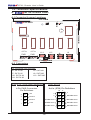
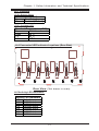
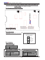
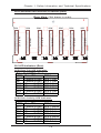
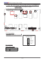
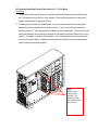
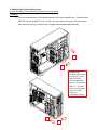
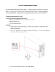
742S
742i
SC742 CHASSIS
USER'S GUIDE
1.0a
SC742 Chassis User’s Guide
The information in this User’s Guide has been carefully reviewed and is believed to be
accurate. The vendor assumes no responsibility for any inaccuracies that may be
contained in this document, makes no commitment to update or to keep current the
information in this manual, or to notify any person or organization of the updates. Please
Note: For the most up-to-date version of this manual, please see our
web site at www.supermicro.com.
SUPERMICRO COMPUTER reserves the right to make changes to the product described in
this manual at any time and without notice. This product, including software, if any, and
documentation may not, in whole or in part, be copied, photocopied, reproduced, translated
or reduced to any medium or machine without prior written consent.
IN NO EVENT WILL SUPERMICRO COMPUTER BE LIABLE FOR DIRECT, INDIRECT,
SPECIAL, INCIDENTAL, OR CONSEQUENTIAL DAMAGES ARISING FROM THE USE OR
INABILITY TO USE THIS PRODUCT OR DOCUMENTATION, EVEN IF ADVISED OF THE
POSSIBILITY OF SUCH DAMAGES. IN PARTICULAR, THE VENDOR SHALL NOT HAVE
LIABILITY FOR ANY HARDWARE, SOFTWARE, OR DATA STORED OR USED WITH THE
PRODUCT, INCLUDING THE COSTS OF REPAIRING, REPLACING, INTEGRATING,
INSTALLING OR RECOVERING SUCH HARDWARE, SOFTWARE, OR DATA.
Any disputes arising between manufacturer and customer shall be governed by the laws of
Santa Clara County in the State of California, USA. The State of California, County of
Santa Clara shall be the exclusive venue for the resolution of any such disputes.
Supermicro's total liability for all claims will not exceed the price paid for the hardware
product.
Unless you request and receive written permission from SUPER MICRO COMPUTER, you
may not copy any part of this document.
Information in this document is subject to change without notice. Other products and
companies referred to herein are trademarks or registered trademarks of their respective
companies or mark holders.
Copyright © 2005 by SUPER MICRO COMPUTER INC.
All rights reserved.
Printed in the United States of America
1-2
Chapter 1: Safety Information and Technical Specifications
Table of Contents
Chapter I: Safety Information and Technical Specifications .......... 1-4
1-1. Safety Information ............................................................................. 1-4
1-2. Technical Specifications .................................................................. 1-6
A.
742 SATA Back Panel ................................................................. 1-6
B. SCA742-E2 SCSI Dual Channel Back Panel (w/GEM318) ................... 1-8
C. SCA 742 SCSI Single Channel Back Panel (w/GEM359) .................. 1-10
D. SCSI (Super) GEM Driver Installation (*for the Windows OS) ....... 1-12
Chapter 2: Installation Instructions ..................................................... 2-1
1-3
SC742 Chassis User’s Guide
Chapter 1-Safety Information and Technical
Specifications
1-1 Safety Information
!
Electric Static Discharge (ESD) can damage electronic components. To prevent damage to your system board, it is
important to handle it very carefully. The following measures
are generally sufficient to protect your equipment from ESD.\
Static-Sensitive Devices
•
Use a grounded wrist strap designed to prevent static discharge.
•
Touch a grounded metal object before removing the board from the antistatic bag.
•
Handle the board by its edges only; do not touch its components, peripheral chips, memory modules or gold contacts.
•
When handling chips or modules, avoid touching their pins.
•
Put the motherboard and peripherals back into their antistatic bags when
not in use.
•
For grounding purposes, make sure your computer chassis provides excellent conductivity between the power supply, the case, the mounting
fasteners and the motherboard.
•
Use only the correct type of onboard CMOS battery as specified by the
manufacturer. Do not install the onboard battery upside down to avoid
possible explosion.
1-4
Chapter 1: Safety Information and Technical Specifications
STOP
To avoid personal injury and property damage, please carefully
follow all the safety steps listed below:
Before accessing the chassis:
1. Turn off all peripheral devices connected to the SC742.
2. Press the power button to power off the system.
3. Unplug all power cords from the system or the wall outlets.
4. Disconnect all the cables and label the cables for easy identification.
5. Use a grounded wrist strap designed to prevent static discharge when
handling components.
Removing the chassis covers:
After completing the above steps, you can remove the covers and install
components/peripheral devices into the chassis as described in Chapter 2.
1. Unlock and remove the screws and fasteners to remove the cover or
components.
2. Save all the screws and fasteners for later use. (If necessary, label these
screws or fasteners for easy identification.)
3. Follow the instruction given in Chapter 2 to remove the chassis covers.
Reinstalling the chassis covers:
To maintain proper system cooling and airflow, do not operate the system
without installing all chassis covers back to the chassis. To reinstall the chassis
covers, please follow the steps listed below:
1. Make sure that all components and devices are securely fastened
on the chassis and there are no loose parts/screws inside the chassis.
2. Make sure that all cables are properly connected to the connectors and ports.
3. Use the original screws or fasteners to install the covers to the chassis.
4. Be sure to lock to the chassis or the system to prevent unauthorized access.
5. For proper cooling, enclose the chassis with covers before operating the
system.
An important note to the user
All images and graphics shown in this manual were based upon the latest
chassis Revision available at the time of publishing. The chassis you’ve
received may or may not look exactly the same as the ones shown in this
manual.
1-5
SC742 Chassis User’s Guide
1-2 Technical Specifications
A.
742 SATA Back Panel
A-1 Connector/Jumper Locations
199.70MM
742 SATA
1
1
D3
JP18
JP25
135.00MM
4-Pin
PWR
4-Pin
PWR
J14
JP26
JP10
JP13
J12
J8
J6
J10
J7
J5
Front View
A-2 Connectors
D3: Overheat LED Indicator
J5: SATA #0
J6: SATA#1
J7: SATA #2
J8: SATA#3
J10: SATA #4
J12: SATA#5
J14: SATA #6
JP26: ACT In
JP10/ JP13: 4-Pin PWR Connectors
Act In (JP26) Pin Definitions
4-Pin PW R Connectors
Pin Definitions
4
+5V
3
Ground
10
9
x
x
x
SATA#3 Act In
SATA#2 Act In
2
Ground
SATA#6 Act In
1
+12V
SATA#5 Act In
SATA#1 Act In
SATA#4 Act In
SATA#0 Act In
2
1-6
1
Chapter 1: Safety Information and Technical Specifications
A-3 Jumpers
JP18: Buzzer Reset
Buzzer Reset (JP18)
Open
Disabled
Closed Enabled (*Default)
JP25: Overheat LED
Overheat Temperature (JP25)
Pins
Definition
Open
450 C
1-2
500 C
2-3
550 C
A-4 Connector/LED Indicator Locations (Rear Side)
Activity LED Indicators
LED#
D12
D13
D14
D15
D18
D21
D22
Drive#
SATA#0: Active
SATA#1: Active
SATA#2: Active
SATA#3: Active
SATA#4: Active
SATA#5: Active
SATA#6: Active
1-7
D22
SATA6
D21
SATA5
D18
Rear View (*Not drawn to scale)
A-5 Activity LED Indicators
J13
J11
SATA4
J9
D15
SATA2
D13
D12
SATA1
SATA0
J4
SATA3
J3
J2
D14
J1
SC742 Chassis User’s Guide
B. SCA 74-E2 SCSI Dual Channel Back Panel (W/GEM318)
Front View
(*Not Drawn to Scale)
JP15
B-2 Connectors
JP10/JP15: 4-Pin PWR Connectors
4-Pin PWR Connectors
Pin Definitions
B-3 Jumpers
4
+5V
3
Ground
2
Ground
1
+12V
JP18: Buzzer Reset
Buzzer Reset (JP18)
Open
Disabled
Closed Enabled (*Default)
SCSI Channel A Jumpers
SCSI Channel B Jumpers
Channel A Jumpers
Jumpers Definition
JP14
Ch.A Delay Start
JP22
Ch.A Remote Start
Channel B Jumpers
Jumpers Definition
JP20
Ch.B Delay Start
JP23
Ch.B Remote Start
1-8
JP18
JP22
742 SCA E2
JP23
JP20
SCSI Chan. A
SCSI Chan.B
JP10
JP14
B-1 Connector/Jumper Locations
Chapter 1: Safety Information and Technical Specifications
B-4 Connector/LED Indicator Locations (Rear)
Rear View (*Not drawn to scale)
SCSI Drive Fail LED Indicators
Drive Fail LED Indicators
LED#
D5
D6
D16
D17
D22
D23
D25
Drive ID#
Channel A-ID#0
Channel A-ID#1
Channel A-ID#2
Channel B-ID#0
Channel B-ID#1
Channel B-ID#2
Channel B-ID#3
SCA#
SCA 1: Fail
SCA 2: Fail
SCA 3: Fail
SCA 4: Fail
SCA 5: Fail
SCA 6: Fail
SCA 7: Fail
SCSI Drive Activity LED Indicators
Drive Activity LED Indicators
LED#
D12
D13
D14
D15
D20
D21
D24
Drive ID#
Channel A-ID#0
Channel A-ID#1
Channel A-ID#2
Channel B-ID#0
Channel B-ID#1
Channel B-ID#2
Channel B-ID#3
SCA#
SCA 1: Active
SCA 2: Active
SCA 3: Active
SCA 4: Active
SCA 5: Active
SCA 6: Active
SCA 7: Active
1-9
Ch. B-ID#3
D24
D25
D21
D23
D20
Ch. B-ID#1
D15
D17
D14
B-5 LED Indicators (Rear)
SCA7
SCA6
Ch. B-ID#2
SCA5
Ch. B-ID#0
Ch. A-ID#2
D16
D6
D12
Ch. A-ID#1
Ch. A-ID#0
D5
SCA4
D22
SCA3
SCA2
D13
SCA1
SC742 Chassis User’s Guide
C. SCA 742 SCSI Single Channel Back Panel (w/GEM359)
Front View
(*Not Drawn to Scale)
C-1 Connector/Jumper Locations
U6
SCSI
JP10
JP26
JP19
C-2 Connectors
JP10/JP26: 4-Pin PWR Connectors
4-Pin PWR Connectors
Pin Definitions
C-3 Jumpers
JP19: Buzzer Reset
Buzzer Reset (JP19)
Open
Disabled
Closed Enabled (*Default)
1-10
4
+5V
3
Ground
2
Ground
1
+12V
+
+
Chapter 1: Safety Information and Technical Specifications
C-4 Connector/LED Indicator Locations (Rear)
Rear View (*Not drawn to scale)
SCSI Drive Fail LED Indicators
Drive Fail LED Indicators
Drive ID#
ID#0
ID#1
ID#2
ID#3
ID#4
ID#5
ID#6
SCA#
SCA 1: Fail
SCA 2: Fail
SCA 3: Fail
SCA 4: Fail
SCA 5: Fail
SCA 6: Fail
SCA 7: Fail
SCSI Drive Activity LED Indicators
Drive Activity LED Indicators
LED#
D12
D13
D14
D15
D20
D21
D22
Drive ID#
ID#0
ID#1
ID#2
ID#3
ID#4
ID#5
ID#6
SCA#
SCA 1: Active
SCA 2: Active
SCA 3: Active
SCA 4: Active
SCA 5: Active
SCA 6: Active
SCA 7: Active
1-11
SCA7
ID#6
D22
D19
D21
D20
D18
ID#5
SCA6
ID#4
D15
D16
D14
C-5 LED Indicators (Rear)
LED#
D5
D6
D7
D16
D17
D18
D19
SCA5
ID#3
ID#2
D7
D6
D12
ID#1
ID#0
D5
SCA4
D17
SCA3
SCA2
D13
SCA1
SC742 Chassis User’s Guide
D SCSI (Super) GEM Driver Installation (*for the Windows OS)
(*Note: This driver is not necessary for other Operating Systems. If
you have two SCA backplanes, you will need to install the driver
twice.)
The driver is located on the Super Micro motherboard driver CD or is
available for download from our FTP site: ftp://ftp.supermicro.com/driver/
Qlogic/
Follow the procedure below to install this driver to your system.
Installing
the driver:
1)
2)
3)
4)
5)
6)
Right click on “My Computer” and choose “Property”.
Select “Hardware” tab and click on “Device Manager”.
Open “Other Devices” or wherever “GEM318/GEM359” is on.
Right click on this device and choose “Property”.
Click on “Driver” tab and choose “Update Driver”.
Click “Next” 2 times, uncheck both “Floppy disk drives” and “CD-ROM
drives”. Then, select the item- “Specify a location,” and choose
“Next”.
7) Click on “Browse” and choose D drive or wherever Supermicro Setup
CD is in.
8) Choose “Qlogic” folder and click on “Open”.
9) System will automatically detect GEM318/GEM359 and install the drive
from this point on.
or,
1) Right click the "My Computer" icon on your desktop and choose
Properties.
2) Click on the Hardware tab and click on "Device Manager" to bring up
the list of system devices.
3) You may see one or two yellow question marks (?) that read QLogic
GEM318/GEM359 SCSI Processor Device. Right click on these,
and choose to uninstall. If two such question marks are present,
uninstall both.
4) Click on Action tab and choose "Scan for Hardware Changes". The
Hardware Wizard program should start up. Click "Next".
5) At the first prompt, choose “Display a list of known device drivers for
the device so that I can choose a specific driver” and click "Next".
6) Choose “Other Devices” and click Next.
7) Choose “Have Disk”, and specify your floppy drive location in the
options box. Then, click "Next".
8) Highlight “Enclosure Services Device” and click "Next".
9) Ignore the warning prompt by clicking "Yes".
1-12
Chapter 1: Safety Information and Technical Specifications
Notes
1-13
Chapter 2 Installation Instructions
The special design of the SC742 chassis allows it to either be used as a tower or as a rackmount
system. There are several versions of the chassis, which differ primarily in the power supply and
IDE/SCSI configuration. Please refer to the following instructions when working on the SC742.
I. Removing the Chassis Side Cover:
You will need to remove the chassis side cover to:
A. Remove or install drives into any of the 5 ¼” drive bays.
B. Replace chassis fans.
C. Access the motherboard.
Procedure:
1. Remove the two screws from the back lip of the side cover (this is the left cover when
looking from the front).
2. Push in the release tab on the cover and push the cover back to the rear of the chassis. It
should stop after moving about ½ inch.
Release Tab
Depress tab
while pushing
cover toward
rear of chassis.
3. You can now lift the side cover up and off the chassis.
A. Removing/Installing Drives into the 5 ¼” Drive Bays:
Procedure:
1. With the side chassis cover removed, you have access to the 5 ¼” drive bays.
2. Remove the screws to the bay you wish to install or remove a component from. The
chassis comes with dummy modules in all the bays to maintain proper airflow – these
should remain in the chassis until you add a component. Note that the top two bays are
combined into a single module. If adding components here you must remove the four
screws corresponding two both bays.
Drive Bays
Remove the
screws for the
drive bay you
wish to add or
remove a
component from.
The upper two
bays are joined
and so have
four screws.
3. After removing the screws, push the drive module out the front of the chassis. For the
floppy drive bay, you must first remove the two faceplates.
4. Attach the dummy rails to the new drive and insert the new drive into the bay. Secure it to
the chassis with the screws you removed. Remember to plug the data and power cables
into the drive. When finished, replace the chassis side cover and secure it with the
screws.
B. Removing/Installing Chassis Fans into the 5 ¼” Drive Bays:
Procedure:
1. To remove the hot-swap chassis fans, grasp the fan handle while squeezing the locking
tab. Pull the fan unit up and out of the chassis. Reverse this procedure to install a fan
(replace with the exact same type of fan).
2. If installing an extended ATX motherboard, you may need to remove the fan mounting
bracket the fans are attached to for better access. To do so, first remove both fans by
following step one. Then unplug the fan cables from the motherboard. Remove the single
screw that attaches the fan mounting bracket to the chassis and lift the bracket out of the
chassis. To replace it, reverse the procedure. The mounting bracket has three tabs that
fit into holes in the chassis – make sure these tabs are inserted into their corresponding
holes to secure the bracket properly.
Fans
Remove the
screw on the
bracket. Pay
attention to the
tabs and the holes
they fit in to.
II. Removing the Front Chassis Cover:
You do not need to remove the front bezel to access the drives:
Procedure
1. Push on the three tabs on the inside left side lip of the front chassis cover. Push the same
side of the cover out about ½ inch. Push on the open side of the cover to remove it from
the chassis (do not try to swing or pull it straight out after opening the left side).
2
1
Front Cover
Push the tabs toward
the lip and (1) push
that side of the
cover out from the
chassis. When freed
about ½”, (2) push
the cover toward the
other side of the
chassis to
completely release
1
2
III. Removing the Top Chassis Cover and Chassis Feet to Install as Rackmount:
You will need to remove the top chassis cover to add rack rails to the chassis:
Note: Rail assemblies are optional. P/N: CSE-PT26B (black) and CSE-PT26.
Procedure
1. Push the release tab in the center of the cover lip while pushing the cover toward the rear
of the chassis at the same time. After the cover stops, lift it off.
2. Each chassis foot has a single screw. Remove the screw then depress the foot’s locking
tab from the inside of the chassis. Slide the foot off.
3. You can now attach rack rails to the top and bottom (now the sides) of the chassis. See
the diagram below.