1
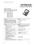
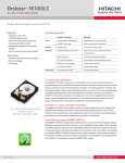
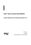
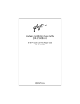
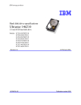
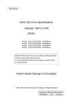
Product Summary Hitachi Ultrastar 10K300 Ultra 320 SCSI hard disk drive Models: HUS103030FL3600 HUS103014FL3600 HUS103073FL3600 HUS103030FL3800 HUS103014FL3800 HUS103073FL3800 Introduction Applications y y y y y y y The new Hitachi Ultrastar 10K300 offers capacities of 300 GB, 147 GB and 73 GB in Ultra 320 SCSI models. The high reliability and excellent performance of the Hitachi Ultrastar 10K300 are the result of the implementation of a number of advanced disk drive technologies, including giant magnetoresistive head technology, NoID sector formatting, Predictive Failure Analysis, and ECC on the fly correction. Features y y y y y y y y y Capacities of 300 GB, 147 GB, 73 GB 68- and 80-pin Ultra 320 industry standard interface Shock: Nonoperational: 250 G (2ms), 75 G (11 ms); Operational: 15 G (11 ms) Rotational speed: 10,000 RPM Average seek time, Read (300GB - 4.7 ms), (147GB – 4.5 ms), (73 GB) Average latency: 2.99 ms Areal density: 61 Gbits/square inch No-ID sector formatting PRML data channel 8 MB (SCSI) buffer for read and write On The Fly correction y Load/Unload heads y y y y Predictive Failure Analysis Giant Magnetoresistive heads No-ID sector formatting Adaptive power save control y y Page 1 Technical/commercial workstations Network servers High-end personal computers CAD/CAM Multimedia Transaction processing Data mining applications Benefits y y Wide range of capacities Interface data rates of 320 MB/s y Robust design for portable computing applications y Excellent data rate across disk surface y Fast access to data y y Increased storage capacity y y y y Fast access to data and improved throughput High reliability Increased durability during power save modes and non-operation High reliability and availability y High areal density, low component count y Low power for battery powered applications More data stored per track, increased sustained data transfer rate version 1.1 Hitachi Global Storage Technologies Electrical connectors Option jumper blocks Pin 1 Address 0 Address 8 Address 1 Address 9 Address 2 Address 10 Address 3 Address 11 Address 4 Address 12 Address 5 Address 13 Address 6 Address 14 Address 7 Address 15 80-pin SCA models (rear view) Uses a DDK connector which is compatible with SCSI Parallel Interface 3 (SPI-3). +5V 68 Pin SCSI Connector Auxiliary Connector A +5V SCSI Pin 1 J4 B Power Pins 1 3 5 7 9 11 13 1 3 5 7 2 4 6 8 10 12 14 2 4 6 8 10 12 14 C :::::: K D E F 1234 L J6 M N G H 68-pin models (rear view) 4 3 2 Pin 1 2 3 4 1 Voltage +12 V GND GND +5V O P I Complies with the ANSI SCSI “P” connector specifications. 9 Q J The drive has two option jumper blocks designated as ‘J-4’ and ‘J-6’ located on the circuit board. J-4 Jumper settings Power pin assignment of 68-pin models ID0 ID2 +5V ID3 ID1 7 5 3 1 12 10 8 6 4 2 11 9 Reserved Ground SCSI ID (address) settings Assign a SCSI address by placing jumpers on the appropriate address pins (D, E, F, and G). Refer to address settings in the illustration above. LED pins The LED pins are used to drive an external Light Emitting Diode. Up to 30 mA of sink current is provided. Refer to the Ultrastar 146Z10 Hard Disk Drive Specifications for a detailed functional description of this pin. Termination Power If a jumper is installed on pins 3 & 4 (position I) of the 68-pin models, termination power is supplied to pins 17, 18, 51, and 52 of the 68-pin SCSI interface. LED Cathode Force SE Mode Auxiliary block of 68-pin models Page 2 Installing a jumper on pins 5 & 6 (position H) causes the drive to function in single-ended mode. version 1.1 Hitachi Global Storage Technologies J-6 Jumper settings Read 147 GB 73 GB Full stroke Full stroke Read Write Enable Auto Spin Up – 68-pin models Installing a jumper on pins 1 & 2 (position Q) on 68-pin models causes the drive to spin up automatically after a power on reset. If this position is not jumpered, the drive will not spin up unless a START UNIT command is received. Disable Auto Spin Up – 80-pin models If pins 1 & 2 (position Q) on 80-pin models are not jumpered, the drive will spin up automatically after a power on reset. Installing a jumper on this position prevents the drive from spinning up unless a START UNIT command is received. Auto Start Delay/Delay Start 6/12 Installing a jumper on pins 3 & 4 (position P) and 5 & 6 (position O) controls when and how the drive spins up in conjunction with pins 1 & 2. When both Auto Spin Up and Auto Start Delay are enabled, the drive start is delayed by a period of time multiplied by the SCSI address of the drive. If Auto Spin Up is disabled, these jumpers will be ignored. Disable SCSI Parity Check Installing a jumper on pins 7 & 8 (position N) disables SCSI Parity checking. 4.5 4.2 10 11 DC power requirements The following voltage specifications apply at the drive power connector. Connection to the drive should be made in safety extra low voltage (SELV) circuits. No special power on/off sequencing is required. +5 volt supply +12 volt supply* 5V ± 5% 12V ± 5% *A deviation up to –8% is acceptable during drive spin up, however spin up time is not guaranteed Power supply current: +5V pop mean (in Amps) Idle average Start up Maximum 0.60 .70 +12V pop mean (in Amps) 300 GB Idle avg 0.68 Seek, peak 2.52 Start upmax 2.45 73 GB Idle avg 0.42 Seek avg 2.15 Start upmax 2.28 147 GB 0.46 2.32 2.45 Generated ripple at drive power connector Enable TI-SDTR Installing a jumper on pins 9 &10 (position M) enables Target Initiated Synchronous Data Transfer Request Negotiation. Disable Unit Attention Installing a jumper on pins 11 &12 (position L) enables control of the Unit Attention Inhibit (UAI) bit in Mode Page 0. During drive start up and seeking, 12-volt ripple is generated by the drive (referred to as dynamic loading). If the power of several drives is daisy chained together, the power supply ripple as well as the dynamic loading of other drives must remain within the regulation tolerance of ±5%. A more desirable method of power distribution is a common supply with separate power leads to each drive. While every effort was made to design the drive not to influence the SCSI bus during these events, it is the responsibility of the system to insure voltage regulation and conformance to operational and nonoperational shock limits. During Hot Plug events the nonoperational shock levels should not be exceeded. The operational shock levels of adjacent drives should also not be exceeded. The recommended procedure is to prohibit write operations to adjacent drives during Hot Plug and Hot Unplug actions. During Hot Unplug the operational shock limit specifications should not be exceeded. If this cannot be guaranteed, the drive should be issued a SCSI Stop Unit command that is allowed to complete before unplugging. The basic requirement is that the operational shock limits are in effect while the drive is operational or spinning down. Once the drive has completely stopped, the nonoperational shock limits are in effect. The recommended procedure is to allow the unplugged drive to rest in the drive bay for a minimum of 15 seconds and then complete the removal. During Hot Plug or Unplug events the power supply ripple on adjacent operational drives should not be outside the ±5% regulation tolerance. SCSI bus connectors and cable Refer to ANSI SCSI Parallel Interface-3 T10/1302D, revision 11, for detailed specifications. Data organization (logical) Model 300 GB 147 GB 73 GB Heads 12 5 3 Seek times (typical - ms) GB Average 300 GB Page 3 Disks 5 3 2 Hot Plug/Unplug support The term 'Hot Plug' refers to the action of mechanically engaging a device to the power and/or bus when other devices may be active on the same bus. (ms) 4.7 version 1.1 Hitachi Global Storage Technologies SCSI bus terminators (optional) Operating environment Acoustics On board SCSI active termination is not supported. The using system is responsible for making sure that all required signals are terminated at both ends of the bus cable. The drive operates within its performance limits when the following environmental conditions are maintained. The criteria of the A-weighted sound power levels are given in Bel relative to one pico watt and are shown in the following table. The measurement method is in accordance with ISO7779. Drives must meet these criteria in both board up and board down orientations. Terminator power Terminator power can be provided by the 5V power supply through current limiter and Schottky diode. This function can be selected by jumper. 80-pin SCA-2 models do not support SCSI bus Terminator Power. Operating conditions Temperature 5 – 55°C Relative humidity 5 – 90% (non condensing) Max wet bulb temp 29 °C (non condensing) Max temp gradient 15°C/hour Altitude (meters) –300 to 3048 Non-operating conditions Vibration and shock Operating vibration The overall RMS (root mean square) vibration level on all axis is 1.0 G. Non-operating vibration The overall RMS level of vibration level on all axix is 5.0 G. Operating shock The drive withstands with no data loss a half-sine shock pulse of 15 G of 11 ms duration. The shock pulses are applied ten pulses for each direction and for all three axes for a total of 60 pulses. There must be a minimum delay of 30 seconds between shock pulses to allow the drive to complete all necessary error recovery procedures. Non-operating shock The drive withstands with no data loss a half-sine shock pulse of 75 G of 11 ms duration and a half-sine shock pulse of 250 G of 2 ms duration. The shocks are applied in each direction of the three mutually perpendicular axes of the drive. Rotational shock The drive withstands with no data loss a rotational shock of 30,000 rad/s2 applied around the axis of the actuator pivot for a duration of 1 ms. Page 4 Temperature: –40 to +70°C Relative humidity 5 – 90% (non condensing) Max wet bulb temp 29°C/hour (non condensing) Max temp gradient 15°C/hour Altitude (meters) –300 to12,000 NOTE: The system must provide sufficient ventilation to maintain a surface temperature not to exceed 60°C at the center of the top cover of the drive. Non-condensing conditions should be kept at all times. Maximum storage period in the shipping package is one year. Corrosion test The hard disk drive shows no signs of corrosion inside or outside of the hard disk assembly and is functional after subjection to a temperature of 50°C with a relative humidity of 90% for seven days A-weighted sound power levels: Idle – Typical (Bels) - 3.4 The acoustical characteristics of the drive subsystem are measured under the following conditions: Idle mode powered on, disks spinning, track following, unit ready to receive and respond to control line commands Operating mode continuous random cylinder selection and seek operation of the actuator with a dwell time at each cylinder. The seek rate Ns is to be calculated according to the following formula: Ns = 0.4/(Tt + T1) where Ns = avg seeks per second Tt = published random seek time, and T1 = time for the drive to rotate by half a revolution. ATTENTION: The drive must be protected against electrostatic discharge (ESD) especially when being handled. The safest way to avoid damage is to put the drive in an anti-static bag before ESD wrist straps are removed. Drives must be shipped in approved containers. Severe damage can be caused to the drive if the packaging does not adequately protect against the shock levels induced when a box is dropped. Consult your Hitachi representative if you do not have an approved shipping container. version 1.1 Hitachi Global Storage Technologies Operating modes Electromagnetic compatibility To provide the greatest flexibility of operation with optimum performance and power consumption, the drive has a number of operating modes. These are defined below. When installed in a suitable enclosure and exercised with a random accessing routine at the maximum data rate, the drive meets the following worldwide EMC requirements: Spin Up Start up time period from spindle stop or power down. United States Federal Communications Commission (FCC) Rules and Regulations (Class B), Part 15 This drive is certified for compliance to EC directive 89/336/EEC C-Tick Mark complies with Australian EMC standard, AS/NZS 3548:1995 Class B The drive complies with Taiwan BSMI EMC standard Seek Seek operation mode Write Write operation mode Read Read operation mode Performance idle The device is capable of responding immediately to media access requests. All electronic components remain powered and full frequency servo remains operational. Physical dimensions Low Power idle Spindle motor is rotating normally with actuator unloaded to the parking positions. Standby The device interface is capable of accepting commands. Spindle motor is stopped. All circuitry except host interface is in power saving mode. The execution of commands is delayed until spindle becomes ready. Height (mm) Width (mm) Length (mm) Weight (grams max) 26.1 101.6±0.25 147.0±0.6 .75 Refer to the illustration below. Mounting The drive will operate in all axes (six directions). To avoid performance degradation the drive must be mounted securely in the system. Drive level vibration tests and shock tests are to be conducted with the drive mounted to the table using the bottom four screws. Refer to the illustration on the next page for mounting positions and tappings. Page 5 version 1.1 Hitachi Global Storage Technologies Mounting and Mechanical dimensions Page 6 version 1.1 Hitachi Global Storage Technologies © Copyright Hitachi Global Storage Technologies Hitachi Global Storage Technologies 5600 Cottle Road San Jose, CA 95193 Produced in the United States 8/04 All rights reserved DeskstarTM is a trademark of Hitachi Global Storage Technologies. Microsoft, Windows XP, and Windows are trademarks of Microsoft Corporation in the United States, other countries, or both. Other product names are trademarks or registered trademarks of their respective companies. References in this publication to Hitachi Global Storage Technologies products, programs or services do not imply that Hitachi Global Storage Technologies intends to make these available in all countries in which Hitachi Global Storage Technologies operates. Product information is provided for information purposes only and does not constitute a warranty. Information is true as of the date of publication and is subject to change. Actual results may vary. This publication is for general guidance only. Photographs may show design models. 17 August 2004 Page 7 version 1.1