1
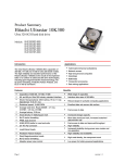
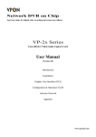
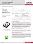
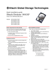
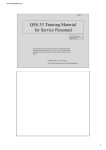
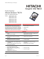
Hitachi Global Storage Technologies
Product Summary
Hitachi Deskstar 7K250
Ultra ATA/100 Hard disk drive
Models:
HDS722540VLAT20
HDS722580VLAT20
HDS722512VLAT20
HDS722512VLAT80
HDS722516VLAT20
HDS722516VLAT80
HDS722525VLAT80
Introduction
Applications
The Hitachi Deskstar 7K250 is ideal for high performance desktop users. These drives feature capacities
from 40 GB to 250 GB, a rotational speed of 7200 RPM,
and average seek times of 8.2 and 8.5 ms. The Hitachi
Deskstar 7K250 combines new and proven technologies
to greatly enhance system performance and capacity.
•
Advanced desktop and audio/video
•
Low-cost routers
•
Switches
•
Video editing
Features
Advantages
•
•
Formatted capacities of 40, 80, 120, 160 and
250 GB
Rotational speed 7200 RPM
•
Supports higher quality digital audio/video storage,
superior digital content creation capabilities, and
significantly faster processing
•
•
Ultra ATA/100 interface
Self Diagnostics on Power On and resident
diagnostics
•
Optimizes system performance
•
Operating shock—No data loss occurs with a
55 G half-sine shock pulse of 2 ms duration
•
•
Protection for drive mishandling
Increased reliability
•
•
Idle power consumption of
5.0 W(40GB & 80GB), 5.9W (120GB &160GB),
7.0 W(250GB)
Circuits and motors optimized to save power and
reduce system temperature
•
•
Lower system power supply and cooling
requirements
Extending system life and reliability
•
•
2048 KB data buffer (8192 KB an option for some
models) (upper 260 KB for firmware)
•
•
•
Fast access to data
•
Improved throughput
•
•
Media-to-buffer transfer rates: 757 Mb/s
Typical seek time(read): 120-250GB – 8.2ms,
40-80GB – 8.5ms
Average latency: 4.17 ms
Complies with ATA 7 specification
•
Fluid Dynamic Bearing and tri-laminate top cover
•
Lower acoustics
Page 1
version 1.0
Hitachi Global Storage Technologies
1
Connectors
DC power requirements
Pin 1
Pin A
Jumper Power
Block Connector
AT I/F
Connector
The DC power connector is designed to mate with AMP p/n 1-80424-0
using AMP strip pins (p/n 350078-4),
loose piece pins (p/n 61173-4), or
their equivalents.
Damage to the drive electronics may
result if the power supply cable is
connected or disconnected while the
power is on. There is no special
power on/off sequencing required.
The following voltage specification is
applied at the power connector of
the drive.
Input
voltage
(Volts)
Note: The AT signal connector is a 40-pin
connector.
Cabling
For systems operating with Ultra
DMA mode 3, 4, or 5, the
80-conductor ATA cable assembly
must be used.
Jumper block
Jumper pin letter designations
I
During run and Absolute
spin up
max spike
(Volts)
voltage
5 ± 5%
7
+12
12 +10% –8%
15
1
G
E
C
A
H
F
D
B
Power supply voltage spikes in excess
of the maximum values specified in the
table may damage the drive electronics.
mA RMS
+5 V +12V
250 GB model
Idle avg
Idle ripple – peak
to peak
Seek peak
1
Seek avg
Start up-max
RND R/W peak
A jumper attaches two pins together
to configure the drive for the proper
mode of operation.
Jumper settings
16 head logical architecture
A-B and G-H
Master active*
Slave active
A-B and C-D
Cable Select
A-B and E-F
Master/Slave present
E-F and G-H
Reserved
I
15 head logical architecture
A-C and G-H
Master active
Slave active
A-C
Cable select
A-C and E-F
Master/Slave present A-C, E-F & G-H
Reserved
I
All other jumper settings are reserved. Do not make other settings!
*Shipping default
RND R/W avg
Standby avg
Sleep avg
Total
Watts
280
470
7.0
230
330
–
590
330
870
790
490
140
100
1950
690
1840
1800
660
20
20
120 GB and 160 GB model
Idle avg
280
375
Idle ripple – p to p 230
250
Seek peak
590
1790
1
330
610
Seek avg
Start up-max
740
1800
RND R/W peak
1252 1600
2
430
590
RND R/W avg
Standby avg
140
20
Sleep avg
100
20
40 GB and 80 GB model
Idle avg
280
Idle ripple – p to p 230
Seek peak
600
1
330
Seek avg
Start up-max
870
RND R/W peak
1252
2
430
RND R/W avg
Standby avg
140
Sleep avg
100
Seek duty = 30%, W/R duty = 45%,
Idle Duty = 25%
Power supply generated ripple
Output
(V)
+5
+12
Maximum Freq. range
(mV p-p)
(MHz)
100
0–10
150
0–10
Hot Plug/Unplug support
Hot plugging/unplugging is not
allowed. Damage to the drive
electronics may result if the power
supply cable is connected or disconnected while power is being applied
to the drive.
Data organization (logical)
Power supply current
2
Page 2
1
+5
1
The length of the cable from the host
system to the drive must not exceed
18 inches.
Random seeks at 40% duty cycle
2
300
220
1550
520
1700
1720
590
20
20
Number of heads
Sectors/track
Number of cylinders
Capacity
(GB)
40
–
80
120
160
250
10.0
–
–
10.3
0.9
0.7
5.9
–
–
6.7
–
–
–
7.9
–
–
Total logical data
bytes
41,174,178,880
82,348,277,760
123,522,416,640
164,696,555,520
250,059,350,016
Electromagnetic compatibility
When installed in a suitable enclosure and exercised with a random
accessing routine at the maximum
data rate the hard disk drive meets
the following worldwide EMC
requirements listed below:
•
United States Federal
Communications Commission
(FCC) Rules and Regulations
(Class B), Part 15.
•
European Economic Community
(EEC) directive number 76/889
related to the control of radio
frequency interference and the
Verband Deutscher
Elektrotechniker (VDE)
requirements of Germany (GOP).
10.1
0.9
0.7
5.0
16
63
16,383
8.3
0.9
0.7
version 1.0
Hitachi Global Storage Technologies
y Average acceleration level =
Environment
50 G. (Average response curve
value during the time following
the 1 ms rise time and before
the 1 ms fall with a time duration
of 11 ms)
Operating conditions
Temperature
Relative humidity
(noncondensing)
Maximum wet
bulb temperature
(noncondensing)
Maximum temperature gradient
Altitude
1
5 to 55°C
8 to 90%RH
y Minimum velocity change
29.4°C
15°C/hour
–300 to 3048 m
1
The system is responsible for providing
sufficient air movement to maintain a
surface temperature below 60°C at the
center of the top cover of the drive.
Non operating conditions
–40 to 65°C
Temperature
Relative humidity
5 to 95%RH
(noncondensing)
Maximum wet
35°C
bulb temperature
(noncondensing)
Altitude
–300 to 12,000m
Operating shock
The drive meets the following criteria
while operating in respective conditions described in the list below.
y
y
y
No error occurs with a 10 G halfsine shock pulse of 11 ms duration
in all models.
No data loss occurs with a 30 G
half-sine shock pulse of 4 ms
duration in all models.
No data loss occurs with a 55 G
half-sine shock pulse of 2 ms
duration in all models.
The shock test consists of ten
shocks inputs in each axis and in
each direction for a total of 60. There
must be a delay between shock
pulses that is long enough to allow
the drive to complete all of the necessary error recovery procedure.
Nonoperating shock
The drives will operate with no degradation of performance after being
subjected to a shock pulses with the
following characteristics. The tests
involved trapezoidal and sinusoidal
shock wave.
Trapezoidal shock wave
y The approximate shape of the
equals 4.23 m/s.
The shape is approximately a halfsine pulse. The following table
shows the maximum acceleration
level and duration.
All models
The upper limit criteria of the octave
sound power levels are given in Bels
relative to one pico watt and are
shown below. The measurement
method is in accordance with
ISO7779.
250 GB model
Sinusoidal shock wave
Acceleration
level (G)
75
300
350
Acoustics
Duration
(ms)
11
2
2
Mode
Idle
Operating
Performance
seek mode
Quiet seek
mode
No data loss is incurred with the
following rotational shocks applied
around the axis of the actuator pivot:
y
y
2
30,000 rad/s for a duration of 1 ms
2
20,000 rad/s for a duration of 2 ms
Max.
(Bel)
3.4
3.4
3.7
3.1
3.5
120GB and 160GB models
Mode
Rotational shock
Typical
(Bel)
3.0
Idle
Operating
Performance
seek mode
Quiet seek
mode
Typical
(Bel)
2.8
Max.
(Bel)
3.2
3.4
3.7
2.9
3.3
40GB and 80 GB models
Mode
Idle
Operating
Performance
seek mode
Quiet seek
mode
Typical
(Bel)
2.6
Max.
(Bel)
3.0
3.4
3.7
2.8
3.2
ATTENTION: The drive
must be protected
against electrostatic
discharge especially
when being handled.
The safest way to
avoid damage is to put the drive in
an anti-static bag before ESD wrist
straps are removed.
Drives must be shipped in approved
containers. Severe damage can be
caused to the drive if the packaging
does not adequately protect against
the shock levels induced when a box
is dropped. Consult your Hitachi
Global Storage Technologies representative if you do not have an
approved shipping container.
pulse is square (trapezoidal).
y Approximate rise and fall time of
pulse = 1 ms.
Page 3
version 1.0
Hitachi Global Storage Technologies
Command descriptions
The following commands are supported by the drive:
Commands
Check Power Mode
Check Power Mode*
Execute Device
Diagnostic
Flush Cache
Format Track
Identify Device
Idle
Idle*
Idle Immediate
Idle Immediate*
Initialize Device
Parameters
NOP
Read Buffer
Read DMA (retry)
Read DMA (no retry)
Read DMA Queued
Read Long (retry)
Read long (no retry)
Read Multiple
Read Native Max
Address
Read Sectors (retry)
Read Sectors (no
retry)
Read Verify Sectors
(retry)
Read Verify Sectors
(no retry)
Recalibrate
Security Disable
Password
Security Erase
Prepare
Security Erase Unit
Security Freeze Lock
Security Set
Password
Security Unlock
Seek
Service
Set Features
Set Max Address
Set Multiple Mode
Sleep
Sleep*
SMART Disable
Operations
S.M.A.R.T. Enable/
Disable Attribute Auto
save
S.M.A.R.T. Enable
Operations
S.M.A.R.T. Execute
Off-line Data
Collection
Page 4
(Hex)
E5
98
P
3
3
90
3
E7
50
EC
E3
97
E1
95
3
2
1
3
3
3
3
91
3
00
E4
C8
C9
C7
22
23
C4
3
1
4
4
5
1
1
1
F8
3
20
1
21
1
40
3
41
3
1x
3
F6
2
F3
3
F4
F5
2
3
F1
2
F2
7x
A2
EF
F9
C6
E6
99
2
3
5
3
3
3
3
3
B0
3
B0
3
B0
3
B0
3
S.M.A.R.T. Read
Attribute Values
S.M.A.R.T. Read
Attribute Thresholds
S.M.A.R.T. Return
Status
S.M.A.R.T. Save
Attribute Values
S.M.A.R.T. Read Log
Sector
S.M.A.R.T. Write Log
Sector
S.M.A.R.T. Enable/
Disable Automatic
Off-line Data
Collection
Standby
Standby*
Standby Immediate
Standby Immediate*
Write Buffer
Write DMA (retry)
Write DMA (no retry)
Write DMA Queued
Write Long (retry)
Write Long (no retry)
Write Multiple
Write Sectors (retry)
Write Sectors (no
retry)
B0
1
B0
1
B0
3
B0
3
B0
1
B0
2
B0
3
E2
96
E0
94
E8
CA
CB
CC
32
33
C5
30
3
3
3
3
2
4
4
5
2
2
2
2
31
2
Protocol
1 PIO data IN command
2 PIO data OUT command
3 Non data command
4 DMA command
5 DMA queued command
+ Vendor specific command
Note: Commands marked * are alternate
command codes for previously defined
commands
Signal definition
Pin
01
02
03
04
05
06
07
08
09
10
11
12
13
14
15
16
17
18
19
(20)
21
22
23
24
25
26
27
28
29
30
31
32
33
34
35
36
37
38
39
40
Signal
RESET–
GND
DD7
DD8
DD6
DD9
DD5
DD10
DD4
DD11
DD3
DD12
DD2
DD13
DD1
DD14
DD0
DD15
GND
Key
DMARQ
GND
DIOW–(**)
GND
DIOR–(**)
GND
IORDY(**)
CSEL
DMACK–
GND
INTRQ
I/O
I
–
I/O
I/O
I/O
I/O
I/O
I/O
I/O
I/O
I/O
I/O
I/O
I/O
I/O
I/O
I/O
I/O
–
–
O
–
I
–
I
–
O
I
I
–
O
Type
(2)
–
(1)
(1)
(1)
(1)
(1)
(1)
(1)
(1)
(1)
(1)
(1)
(1)
(1)
(1)
(1)
(1)
–
–
(1)
–
(2)
–
(2)
–
(1)
(2)
(2)
–
(1)
DA1
PDIAG–
DA0
DA2
CS0–
CS1–
DASP–
GND
I
I/O
I
I
I
I
I/O
–
(2)
(3)
(2)
(2)
(2)
(2)
(3)
–
Notes:
Type:
(1) 3-state
(2) TTL
(3) open-collector or open drain
output
O – an output from the drive.
I - an input to the drive.
"I/O" designates an input/output common.
The signal lines marked with (**) are redefined during the Ultra DMA protocol to
provide special functions. These lines
change from the conventional to special
definitions at the moment the Host decides to allow a DMA burst if the Ultra
DMA transfer mode was previously
chosen by means of SetFeatures. The
Drive becomes aware of this change
upon assertion of the DMACK– line.
These lines revert back to their original
version 1.0
Hitachi Global Storage Technologies
definitions upon the deassertion of
DMACK– at the termination of the DMA
burst. See the table below.
Ultra DMA definitions
Special definition (for Ultra
DMA)
DDMARDY–
Write HSTROBE
STOP
Conventional
definition
IORDY
DIOR–
DIOW–
DIOR–
IORDY
DIOW–
HDMARDY –
Read DSTROBE
STOP
Mechanical data
Height
Width
Length
25.4 mm ± 0.4
101.6 mm ± 0.4
146.0 mm ± 0.6
Weight (maximum)
640 grams
Mounting
The drive will operate in all axes (six
directions). Performance and error
rate will stay within specification
limits if the drive is operated in the
other permissible orientations from
which it was formatted.
For reliable operation the drive must
be mounted in the system securely
enough to prevent damage from
excessive motion or vibration during
seek operation or spindle rotation,
using appropriate screws or equivalent mounting hardware.
Drive level vibration test and shock
test are to be conducted with the
drive mounted to the table using the
bottom four screws.
Mounting holes
Dimension
reference
number
Dimension
(mm)
(1)
(2)
(3)
(4)
(5)
(6)
(7)
41.28 ± 0.5
44.45 ± 0.2
95.25 ± 0.2
6.35 ± 0.2
28.5 ± 0.5
60.0 ± 0.2
41.6 ± 0.2
Mounting screw thread count = 6-32 UNC
Notes: Recommended screw torque to be applied to mounting screws is 0.6–1.0 Nm (6–10 kg-cm).
Page 5
version 1.0
Hitachi Global Storage Technologies
Mechanical dimensions
25.4
}0.4
101.6
}0.4
146
}0.6
BREATHER
HOLE (*)
Dia. 2.0
38.9
}0.4
19.7
0.4
LEFT
}0.1
}
FRONT
* DO NOT BLOCK THE
BREATHER HOLE.
Page 6
version 1.0
© Copyright Hitachi Global Storage
Technologies
Hitachi Global Storage Technologies
5600 Cottle Road
San Jose, CA 95193
Produced in the United States
7/03
All rights reserved DeskstarTM is a trademark of
Hitachi Global Storage Technologies.
Microsoft, Windows XP, and Windows are
trademarks of Microsoft Corporation in the
United States, other countries, or both.
Other product names are trademarks or
registered trademarks of their respective
companies.
References in this publication to Hitachi Global
Storage Technologies products, programs or
services do not imply that Hitachi Global
Storage Technologies intends to make these
available in all countries in which Hitachi Global
Storage Technologies operates.
Product information is provided for information
purposes only and does not constitute a warranty.
Information is true as of the date of publication
and is subject to change. Actual results may
vary.
This publication is for general guidance only.
Photographs may show design models.
22 July 2003