1
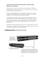
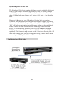
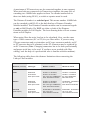
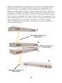
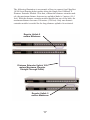
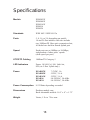
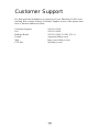
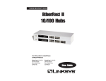
Instant EtherFast® Series
EtherFast 10/100
Auto-Sensing
Hubs
Use this guide to install these
Linksys products:
EtherFast 10/100
5-Port Hub
(EFAH05W)
EtherFast 10/100
8-Port Hub
(EFAH08W)
EtherFast 10/100
16-Port Hub
(EFAH16W)
EtherFast 10/100
16-Port Rack
Mountable Hub
(EFAH16)
EtherFast 10/100
24-Port Rack
Mountable Hub
(EFAH24)
User Guide
COPYRIGHT & TRADEMARKS
Copyright © 1998 Linksys, All Rights Reserved. Instant EtherFast is a registered trademark of Linksys. Microsoft, Windows, and the Windows logo are registered trademarks
of Microsoft Corporation. All other trademarks and brand names are the property of
their respective proprietors.
LIMITED WARRANTY
Linksys guarantees that every EtherFast 10/100 Auto-Sensing Hub (Workgroup
Models: 5, 8, and 16-Port; Rackmount Models: 16 and 24-Port) is free from physical
defects in material and workmanship under normal use for five (5) years from the date
of purchase. If the product proves defective during this warranty period, call Linksys
Customer Support in order to obtain a Return Authorization number. BE SURE TO
HAVE YOUR PROOF OF PURCHASE ON HAND WHEN CALLING. RETURN
REQUESTS CANNOT BE PROCESSED WITHOUT PROOF OF PURCHASE. When
returning a product, mark the Return Authorization number clearly on the outside of the
package and include your original proof of purchase.
IN NO EVENT SHALL LINKSYS’ LIABILITY EXCEED THE PRICE PAID FOR THE
PRODUCT FROM DIRECT, INDIRECT, SPECIAL, INCIDENTAL, OR CONSEQUENTIAL DAMAGES RESULTING FROM THE USE OF THE PRODUCT, ITS ACCOMPANYING SOFTWARE, OR ITS DOCUMENTATION. Linksys makes no warranty or representation, expressed, implied, or statutory, with respect to its products or the contents
or use of this documentation and all accompanying software, and specifically disclaims
its quality, performance, merchantability, or fitness for any particular purpose. Linksys
reserves the right to revise or update its products, software, or documentation without
obligation to notify any individual or entity. Please direct all inquiries to:
Linksys P.O. Box 18558, Irvine, CA 92623.
FCC STATEMENT
This equipment has been tested and found to comply with the limits for a Class A digital device, pursuant to Part 15 of the FCC Rules. These limits are designed to provide
reasonable protection against harmful interference in a residential installation. This
equipment generates, uses, and can radiate radio frequency energy and, if not installed
and used according to the instructions, may cause harmful interference to radio communications. However, there is no guarantee that interference will not occur in a particular installation. If this equipment does cause harmful interference to radio or television
reception, which is found by turning the equipment off and on, the user is encouraged
to try to correct the interference by one or more of the following measures:
•
•
•
•
Reorient or relocate the receiving antenna
Increase the separation between the equipment or device
Connect the equipment to an outlet other than the receiver’s
Consult a dealer or an experienced radio/TV technician for
assistance
0998
Contents
Introduction
2
About Fast Ethernet
3
Planning Your Network
4
Installing the Hub
5
LED Indicators
6
Optional Fiber Optic Expansion Modules
7
Mounting the Hub
7
Connecting Nodes to the Hub
7
Uplinking the Hub
8
Uplinking the 5-Port Hub
9
Powering On and Resetting the Hub
10
Appendix
Twisted Pair Cabling
11
Installing Add-On Modules
12
Fiber Optic Modules
13
100BaseTX Distance Extender Module
16
Specifications
18
Customer Support
19
Introduction
The EtherFast 10/100 Auto-Sensing series of hubs from Linksys is the
fastest, most economical way to build or expand an enterprise 100Mbps
network! Ready to run right out of the box, each 10/100 hub lets you connect computers or other nodes together in seconds, with auto-sensing ports
that automatically adjust to either 10Mbps or 100Mbps speeds -- mix
10BaseT and 100BaseTX hardware together any way you like! Combine
low-cost 10Mbps computers with high-speed Fast Ethernet workstations-save thousands of dollars by putting 100Mbps hardware only where you
need it most!
Each hub includes a built-in uplink port that lets you plug into 10Mbps or
100Mbps hubs, stacking hubs, switches, or backbones for easy future
expansion. Advanced error handling, auto partitioning, data collision control, and auto polarity correction protect your data during transmissions.
Compatible with virtually all operating systems like Windows 98,
Windows 95, Windows NT, and Novell NetWare, the professional-grade
Auto-Sensing series of hubs offers your growing enterprise network the
freedom to use both 10Mbps and 100Mbps speeds, together with an amazing range of expansion possibilities -- all for an attractive price that’s hard
to beat!
About This Guide
This guide explains how to install and use a number of different EtherFast
10/100 Auto-Sensing Hub models. Some models are rack mountable, while
others are designed for desktop use. All of the models can be used interchangeably.
2
About Fast Ethernet
As the demand for desktop video, multimedia development, imaging, and
other speed-intensive applications continues to rise, the need for high performance, fault tolerant LAN technology will become more critical.
Standard Ethernet, which has been the most popular networking technology to date with a maximum data throughput of 10 Megabits per second, is
becoming insufficient to handle the latest video, multimedia, and other
speed-intensive client/server LAN applications.
Among the solutions to the problem of network speed, Fast Ethernet has
emerged as the most viable and economical. Capable of sending and
receiving data at 100 Megabits per second, it is more than fast enough to
handle even the most demanding video and other real-time applications.
Although there are a number of different competing Fast Ethernet implementations, 100BaseTX is by far the most popular. Operating on two pairs
of Category 5 unshielded twisted-pair (UTP) cabling, 100BaseTX supports
high speed signaling and is relatively inexpensive. Because it uses four
wires for data transmission and the same packet format, packet length,
error control, and management information as 10BaseT, 100BaseTX can
be made to communicate with slower 10BaseT equipment when routed
through a switch.
This backward compatibility is one of 100BaseTX's major advantages
over other forms of Fast Ethernet; it allows critical, speed-dependent network segments to be upgraded to 100BaseTX speeds as needed without rewiring, refitting, and retraining an entire site. Networks can now mix both
slow and fast network segments for different users or departments. Publishing, R&D, video, multimedia, or accounting departments can enjoy a
100Mbps pace, while other corporate segments can operate at slower and
more affordable 10Mbps speeds.
Every port on your Auto-Sensing Hub is capable of running at either
10Mbps or 100Mbps, allowing you to mix and match economical 10BaseT
hardware with high performance 100Mbps network cards, hubs, switches,
and other equipment.
3
Planning Your Network
The rules that govern how nodes and hubs are distributed across a network
are important to ensure the integrity of your data. Cabling specifications,
distance limits, and other topology rules must be followed in order to avoid
collisions or data loss.
The Auto-Sensing Hub is equipped with RJ-45 ports that can automatically
adjust to either 10Mbps or 100Mbps speeds. Each port can operate at
either speed, completely independent of the other ports’ speeds, and can be
connected to a workstation, file server, print server, hub, or another node
with twisted-pair cabling.
Although there are different grades of cabling, you must use EIA 568
Category 5 unshielded twisted-pair (UTP) for each connection you make,
and each cable should not exceed 100 meters, (328 feet), in length. Fast
Ethernet networks require Category 5 cabling. Category 5 cabling can be
obtained at most computer stores, or you can crimp your own. See page 11
for cabling specifications. Here are some important cabling rules to follow:
· Computers should never be connected directly together on a network.
They should always be connected to a hub.
· Only two 100Mbps Fast Ethernet hubs can be cascaded, (or uplinked),
together. To cascade more than 2 100Mbps hubs, a switch or a repeater
must be used.
· The maximum cable length from a node to a repeater, switch, or hub is
100 meters (328 feet).
· The maximum length for a Category 5 cable between a 100BaseTX or
10BaseT workstation and a stackable or other shared bandwidth hub is
100 meters (328 feet).
· The maximum distance between 2 100BaseTX hubs without a switch is
5 meters (16.4 feet).
· The maximum distance between 2 10BaseT hubs, (or a 10BaseT hub and
an Auto-Sensing hub), is 100 meters (328 feet).
4
Installing the Hub
Carefully remove the hub from its packaging. Make sure that you received
all of the items listed below. If any items are missing or damaged, contact
your Linksys dealer for replacement part(s).
· EtherFast 10/100 Auto-Sensing Hub
· AC Power Adapter and/or a Power Cord, (with rackmount models)
· User Guide and Registration Card
If you purchased a rack mountable Auto-Sensing hub, your package also
includes rack mounting hardware suitable for securing the hub in a standard hub rack.
Front and Back Panels
The front of each Auto-Sensing Hub includes:
· 10/100 RJ-45 ports that can be connected to workstations, computers, or
file servers with straight-through category 5 cabling
· an Uplink port that can be used for connecting to other hubs, switches, or
routers with straight-through category 5 cabling (see pages 8-9 for more
information about uplinking)
· diagnostic LED indicators to help simplify network monitoring and troubleshooting (see below)
5
LED Indicators
Power
Indicates that the hub is receiving power.
100/10 Col
Indicates if collisions are being encountered at
100Mbps and/or 10Mbps. Some collisions are
normal. If your network seems to be experiencing high collision levels, verify that your
cabling is good, and that there are no cabling
coils, cross-overs, or breaks.
100
ON if a given port is operating at 100Mbps; OFF
if the port is running at 10Mbps.
Link/Act
ON or flickering if a given port is sending or
receiving data; OFF if the port is not connected to a node.
FX1/FX2
ON if the hub’s optional expansion module is
installed. Flickering when receiving or transmitting data. FX2 is on when a dual-port module is
being used, FX1 is on when a single-port or
dual-port module is being used, (rackmount
models only).
SW (EFAH05 only)
ON if uplink port is in 100Mbps/100 meter
Distance Extender mode.
6
Optional Fiber Optic Expansion Module
The Auto-Sensing 16 and 24-Port rack mountable hubs each come with a
fiber optic expansion slot which accepts an optional 100BaseFX fiber
optic module for connecting to high-speed fiber cabling. If you purchased
an optional fiber optic expansion module, set it up by following the setup
instructions included in the Appendix of this guide, (page 13).
Mounting the Hub
Each rack mountable hub is equipped with mounting holes that can be
used to secure it in a stationary or movable 19” rack. If you purchased a
rack mountable hub, use the rack mounting hardware that came with it to
secure the hub in your rack. Follow the instructions that came with your
rack for detailed mounting instructions.
Connecting Nodes to the Auto-Sensing Hub
The Auto-Sensing Hub can be connected to either 10Mbps or 100Mbps
PCs, workstations, file servers, print servers, or other hardware. When
powered up, each of the hub’s 10/100 ports will automatically adjust to the
proper speed, as determined by the speed of the hardware or node connected to the port.
Connect each of your PCs, workstations, file servers, print servers, or other
network nodes to the Auto-Sensing Hub one by one. Each node should be
connected to the hub with a straight-through, RJ-45, Category 5 cable.
Each cable should be less than 100 meters (328 feet), in length. Ready-touse network cables of various lengths can be purchased at most computer
stores. If you wish to crimp your own cabling for custom sites or lengths,
see page 11 for cabling specifications.
When connecting a PC to a hub, either the computer or the hub must be
powered OFF. If both the computer and the hub are turned on while the
connection is completed, the network will act erratically and you must
reset the hub (see page 10).
If the Uplink port is in use (connected to another hub, etc.), the AutoSensing Hub’s last port next to the Uplink port must remain empty and
unused. As in most hubs, the Auto-Sensing Hub’s Uplink port and the port
adjacent to it are joined together inside the hub, and one cannot be used
while the other is in use. If you have an 8-port auto-sensing hub, for example, port 8 cannot be used if the Uplink port is in use, and vice-versa.
7
Connecting the Auto-Sensing Hubs to Other Hubs,
Switches, or Routers
Like most hubs, the Auto-Sensing Hubs can be uplinked to 10Mbps or
100Mbps hubs, stackable hubs, switches, or routers. The front of each hub
has an Uplink port for this purpose.
If you are connecting the hub to a Fast Ethernet hub, router, or switch,
remember that Fast Ethernet rules only allow two hubs to be connected
together, or cascaded, within a single repeater domain.
To uplink the hub, simply connect a regular straight-through Category 5
cable from the Auto-Sensing Hub’s Uplink port to any regular network
port on the hub, switch, or router being uplinked. The Auto-Sensing Hub
will automatically determine the optimum speed of the device being
attached to it.
Remember that while the Uplink port is in use, the port adjacent to it must
remain open, and should not be connected to any cable or node. See page 4
for important limitations when cascading hubs.
Uplinking the Hub
8
Uplinking the 5-Port Hub
The EtherFast 5-Port Auto-Sensing Hub has a special switched uplink port
with it’s own distance extension capabilities. If you are mixing 10Mbps
and 100Mbps hardware on your 5-Port hub, the hub can be uplinked to
other 100Mbps hubs at a distance of 5 meters (16.4 feet) -- just like other
hubs.
However, if all ports on your 5-Port Auto-Sensing hub are running at
100Mbps, then the uplink port automatically becomes capable of sending
data over an uplink cable of up to 100 meters (328 feet). The LED marked
‘SW’ will light up, indicating that a 100 meter uplink can be established.
Please note that in order for the distance extending switch to become
active, all four remaining ports on your 5-Port hub must be running at
100Mbps, (remember that one port on the hub is lost when the hub is
uplinked). This feature is only present on the 5-Port Auto-Sensing hub. All
other auto-sensing hubs can only be uplinked using 5 meter cables when
connecting to 100Mbps Fast Ethernet hubs.
Uplinking the 5-Port Hub
9
Powering On the Hub
Desktop Model
The hub comes with both a power adapter and in some instances, an AC
electrical cord. Plug the power adapter’s plug into the hub’s power jack.
Plug the provided AC electrical cord into the power adapter. Finally, plug
the other end of the electrical cord into a standard AC electrical outlet. The
hub will put itself through a series of diagnostic tests -- which shouldn’t
take more than just a few seconds -- then begin scanning the ports for live
nodes. The installation is complete.
Rack Mountable Model
To power on the hub, plug the supplied AC electrical power cord into the
back of the hub. Turn on the hub. The hub will put itself through a series of
diagnostic tests -- which shouldn’t take more than just a few seconds -then begin scanning the ports for live nodes. The installation is complete.
Resetting the Hub
To reset the hub, turn the unit off for at least three seconds and then turn it
back on.
If you have a rack mountable model, you can use the reset button in the
back of the hub to run the reset power cycle. Use a small screwdriver or
other pointy object that can fit through the hole on the back of the unit and
reach the button. Hold the button for 2 or 3 seconds, then let go. The hub
is reset.
Note: If you power cycle the hub or hold down the reset button for too
long, you may lose some connections.
10
Appendix
Twisted Pair Cabling
There are different grades, or categories, of twisted-pair cabling. Category
5 is the most reliable and widely compatible, and is required for Fast
Ethernet.
You can buy Category 5 cabling that is pre-made, or you can cut and crimp
your own. Category 5 cables can be purchased or crimped as either
straight-through or crossed. A Category 5 cable has 8 thin, color-coded
wires inside that run from one end of the cable to the other. Only wires 1,
2, 3, and 6 are used by Ethernet networks. In a
straight-through cable, wires 1, 2, 3, and 6 at one
end of the cable are also wires 1, 2, 3, and 6 at the
other end. In a crossed cable, the order of the
wires change from one end to the other: wire 1
becomes 3, and 2 becomes 6 and vice versa.
The color code for the 4 wires should be as follows: Wire 1, white with an
orange stripe; Wire 2, orange; Wire 3, white with a green stripe; Wire 6,
green. The other four wires have to be connected as follows: Wire 4, blue;
Wire 5, white with a blue stripe; Wire7, white with a brown stripe, Wire
8, brown.
To figure out which wire is wire number 1, hold the
cable so that the end of the plastic RJ-45 tip (the part that
goes into a wall jack first) is facing away from you. Flip
the clip so that the copper side faces up (the springy clip
will now be parallel to the floor). When looking down on
the coppers, wire 1 will be on the far left.
11
How To Install An Add-On Module
Follow the following steps to install the add-on modules in the EtherFast
10/100 Auto-Sensing Hub (EFAH16 or EFAH24).
1. Power off the hub and remove the AC power cord from the hub.
2. Remove all RJ-45 cables from the all the ports in the hub and if the hub
is on a rack remove the hub from the rack
3. Using a Philips screw driver, remove the screws holding the small cover
panel on the back of the hub. The size of the panel is about 8.1cm by
3.5cm (3.1" x 1.4"). You will need the screws to secure the add-on module
later.
4. Ground yourself properly and remove the add-on module from its package.
5. Hold the module so the chips and the components on the add-on module
are facing up. If the module has a daughter board (a bigger board mounted
on the main board of the add-on module), the bottom of the daughter board
should be facing up. Insert the module into the back of the hub.
6. The add-on module will slide in until it comes to a stop. Push the module to make sure it makes a proper connection. Note: Do not use too much
force, you can bend the metal panel on the add-on module.
7. Secure the module in place with the two screws.
8. If used on a rack, mount the hub back on the rack. Reconnect the RJ-45
cables and the AC Power cord. Note: do not connect any cables to the
port(s) that will be used by the add-on Module (see page 14 to find which
ports can't be used when using an add-on module).
9. Connect your Fiber cable or RJ-45 cable to the add-on Module. Turn on
the hub.
12
Fiber Optic Modules
Six different Fiber Optic modules are available for the rack mountable
Auto-Sensing hubs (EFAH16 and EFAH24):
FFOSC1:
FFOSC2:
FFOST1:
FFOST2:
FFOSCDE1:
FFOSTDE1:
100BaseFX 1-Port Transceiver Module (SC)
100BaseFX 2-Port Transceiver Module (SC)
100BaseFX 1-Port Transceiver Module (ST)
100BaseFX 2-Port Transceiver Module (ST)
100BaseFX 1-Port Distance Extender Module (SC)
100BaseFX 1-Port Distance Extender Module (ST)
When a single port module is used on EFAH24, port 12 cannot be used. If
used on the EFAH16, port 15 cannot be used. The module uses up one
connection.
When the dual port module is used on EFAH24, ports 12, 24, and uplink
cannot be used. If used on the EFAH16, ports 15,16, and uplink cannot be
used.
Each Fiber port has two connectors, a transmit (TX) and a receive (RX).
To connect two modules together, you must run a cable from the transmit
connector on one module to the receive connector on the other. If you are
looking at the back of the hub, the connector on the right is the receiver
and the connector on the left is the transmitter. The connectors are also
labeled on the top of the fiber port. These labels can not be seen after the
module is installed, so make sure that you look before you slide it in.
Each Distance Extender Modules has a switch on the back for Full Duplex
or Half Duplex. The switch must be set to Half Duplex at all times, when
connecting to another Distance Extender or a Transceiver module. The
Link LED will light up when there is a connection made, and the Activity
(ACT) LED will flicker while data is being transmitted or received.
Each Port on the add-on modules has a corresponding jumper on the main
board of the module. If the jumper is removed, the corresponding fiber
port will become disabled and the correspodoning RJ-45 port on the front
of the hub may be used. When the jumper is connecting the pins, the port
is enabled, when the jumper is removed the port is disabled. The dual port
transceiver module has two jumpers, one for each port.
13
A maximum of 2 Transceivers can be connected together in one segment.
When two hubs are connected via Transceivers together, the same rule of
cascading two 100Mb hubs applies to them. To cascade another hub to
these two hubs (using RJ-45), a switch or repeater must be used.
The Distance Extender is a switched port. This means another 100Mb hub
can be cascaded (with RJ-45) to the hub that has a Distance Extender
Module installed. Two Distance Extender modules can be connected together only at Half Duplex. Do NOT set either or both of the Distance
Extender modules to Full Duplex. The Auto-Sensing hubs will not communicate at Full Duplex.
When using fiber the noise loss has to be calculated. Also, use the same
type of fiber connector (SC or ST) for you fiber cables. If you are using
ST-type connectors and you introduce an SC-type connector module, an SC
to ST converter has to be obtained, or the ST connector may be replaced by
an SC Connector (Note: Changing connectors has to be done professionally
and proper tools have to be used. If you have never worked with fiber
cabling, seek the help of a professional who is familiar with the medium).
The following table shows the distance limitation when connecting the
Linksys Fiber modules:
Distance (meters/ft)
Cable type
Module in Hub A
Module in hub B
16/50
Multi-Mode
62.5/125uM
Fiber Optic Cable
FFOSC1 or FFOSC2,
FFOST1 or FFOST2
SC or ST Type 100BaseFX
Fiber Transceiver Module
FFOSC1 or FFOSC2,
FFOST1 or FFOST2
SC Type 100BaseFX
Fiber Transceiver
208/672
Multi-Mode
62.5/125uM
Fiber Optic Cable
FFOSC1 or FFOSC2,
FFOST1 or FFOST2
SC or ST Type 100BaseFX
Fiber Transceiver Module
FFOSCDE1, FFOSTDE1
SC or ST Type
Fiber Distance Extender
412/1330
(Half Duplex)
Multi-Mode
62.5/125uM
Fiber Optic Cable
FFOSCDE1 or FFOSTDE1
SC or ST Type
Fiber Distance Extender
FFOSCDE1, FFOSTDE1
SC or ST Type
Fiber Distance Extender
14
The following illustration is an example of how to connect four Rack Mountable
EtherFast 10/100 Auto-Sensing hubs together using fiber optic cabling. Notice
that the hubs at the top and the bottom are equipped with 100BaseFX 1-Port
Distance Extender modules, while the two hubs in the middle have 100BaseFX 2Port Tranceiver Modules. The distance extender modules allow data to be sent up
to 208 meters (672 feet). The distance between the two hubs with tranceiver modules is limited to a maximum of 16 meters (50 feet). For a full explanation of fiber
optic cabling distance rules, see the chart on page 15. Note: In the illustration, no
other 100Mbps hubs can be cascaded to hubs B and C with RJ-45 cabling.
Another 100Mbps hub can be connected to either hub A or hub D with RJ-45
cabling with no problems.
A
Maximum distance of
208 meters
B
Maximum distance
of 16 meters
C
D
Maximum distance of
208 meters
15
100BaseTX Distance Extender Module
This module has a special distance extending port that sends data at
100Mbps over regular 100BaseTX Category 5 cabling. The distance extender module sends your data up to 100 meters (328 feet). This module is
ideal for connecting to file servers or uplinking to remote hubs.
This module is available for the Rack Mountable Auto-Sensing hubs, (No.:
EFAH16, EFAH24):
EFFETXDE: 100BaseTX Distance Extender Module (Single Port)
When this module is used on the EFAH24, port 12 cannot be used. If the
module is used on the EFAH16, port 15 cannot be used. The module uses
up one connection on the hub, and thus one of the ports becomes disabled.
These rules apply only to times when the module is in use.
Up to four 100BaseTX hubs can be connected together when this module
is used in an auto-sensing hub. Since the 100BaseTX Distance Extender
module is a switched port, another 100BaseTX hub can be cascaded to the
hub with the Distance Extender module installed in it. In addition, two
100BaseTX hubs cascaded together can be connected to the 100BaseTX
Distance Extender module. The usual Fast Ethernet distance limitation
apply when cascading two 100Mbps hubs together, (see page 4 for details).
The distance extender port on the add-on module can be disabled by
removing the corresponding jumper on the module. In the Auto-Sensing
hubs, this module can only be used in half duplex mode
You need to use a crossover cable to connect the module to another hub. If
you are using a straight-through cable, you must run the cable between the
module and the uplink port on the second hub (see illustration on page 17).
The module’s Link LED will light up when a connection is made and the
Activity (ACT) LED will flicker while data is being transmitted or
received.
16
The following illustration is an example of how to connect four EtherFast
10/100 Auto-Sensing hubs together using the Single-Port 100BaseTX
Distance Extender Module. Note that, without the distance extender module, the maximum distance between two uplinked hubs is 5 meters (16.4
feet). With the distance extender module installed on one of the hubs, the
maximum distance becomes 100 meters (328 feet). Only one distance
extender module is needed for the long-distance uplink to be activated.
Regular Uplink 5
meters Maximum
Distance Extender Uplink 100
meters Maximum (Regular
Straight-Through Cable)
Regular Uplink 5
meters Maximum
17
Specifications
Models
EFAH05W
EFAH08W
EFAH16W
EFAH16
EFAH24
Standards
IEEE 802.3 IEEE 802.3u
Ports
5, 8, 16, or 24, depending on model;
16 and 24-Port models each also include
two 100BaseFX fiber optic expansion slots;
All hubs have built-in shared uplink port
Speed
Each port runs at 10Mbps or 100Mbps,
independent of other ports’ speeds
(dual-speed per port)
UTP/STP Cabling
100BaseTX Category 5
LED Indicators
Power, 10/100 Col, 100, Link/Act,
SW (on 5-Port Uplink only)
Power
EFAH05W
EFAH08W
EFAH16W
EFAH16
EFAH24
Power Consumption
8-22 Watts depending on model
Dimensions
Desktop models vary
Rack mountable models: 16.9” x 8” x 1.75”
Weight
Varies; 1 lb. to 7 lbs. max.
18
7.5VDC, 1A
5VDC, 3-6 A
5VDC, 3-6 A
90-250VAC, 50-60Hz
90-250VAC, 50-60Hz
Customer Support
For help with the installation or operation of your EtherFast 10/100 AutoSensing Hub, contact Linksys Customer Support at one of the phone numbers or Internet addresses below.
Customer Support
Fax
Bulletin Board
E-mail
Web
FTP Site
949-261-1288
949-261-8868
949-261-2888 (33.6K, 8-N-1)
[email protected]
http://www.linksys.com
ftp.linksys.com
19
h t t p : / / w w w. l i n k s y s . c o m
© Copyright 1999 Linksys, All Rights Reserved.
Printed in the USA.