1
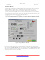
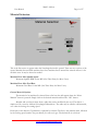
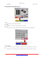
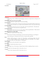
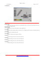
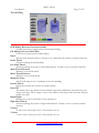
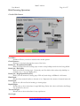
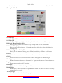
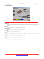
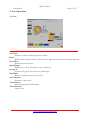
User’s Manual
Version 2.75
Revised 10/29/2007
Mach3 Addons
User Manual
Page 2 of 27
Table of Contents
.................................................................................................................................
3
Basic Operational Flow:
.................................................................................................................................
4
Interface Basics:
.................................................................................................................................
6
Included Operations:
.................................................................................................................................
8
Material Selection
.................................................................................................................................
9
Tool Properties
.................................................................................................................................
11
Navigating through Operations:
.................................................................................................................................
13
Appendix 1 - Operations Screen Definitions
.................................................................................................................................
14
Milling Operations.........................................................................................................................................14
Cut Arc........................................................................................................................................................14
Cut Circle....................................................................................................................................................15
Cut Keyway................................................................................................................................................16
Surface Material.........................................................................................................................................17
Thread Milling........................................................................................................................................... 18
Hole Patterning Operations.........................................................................................................................19
Circular Hole Pattern................................................................................................................................19
Linear Hole Pattern.................................................................................................................................. 21
Rectangular Hole Pattern.........................................................................................................................23
Multiple Hole Position..................................................................................................................................25
Pocketing Operations....................................................................................................................................26
Circular Pocket..........................................................................................................................................26
Rectangular Pocket...................................................................................................................................27
4th Axis Operations......................................................................................................................................28
Cut Gear.....................................................................................................................................................28
Cut Spline...................................................................................................................................................29
Electrical Shapes........................................................................................................................................30
www.newfangledsolutions.com
Mach3 Addons
User Manual
Page 3 of 27
Introduction:
This manual has been assembled in an effort to provide the user with some basic information about
the layout, functionality, and overall use of the Mach3 Addons from Newfangled Solutions LLC. It
is intended to provide the beginning user with some very basic information that will hopefully help
decrease the time necessary to go from “Start to Part”. The format this manual follows is simple we begin with some very basic user interface items, we give some information about each of the
wizard operations included, and we give some basic suggestions for material settings. Each wizard
operation then has its own chapter where all terms used in that operation are defined.
Basic Operational Flow:
Throughout Mach3 Addons for Mill, the user will be required to enter information. It is this
information that will be used for all of the built in functions of the software. Through the course of
conducting a selected operation, the user will progress from the initial Material Selection Screen, to
the Operation Selection Screen, to the Tool Properties Screen, to the Operation Specific Screen,
where the user can Post Code. At this point the user will have completed an operation, and could
exit to Mach3 to run that operation. However, the user can also continue to select operations
allowing the production of more complex parts from a single G-code File. Each operation is clearly
differentiated in the created G-code, making this an effective teaching tool, or just easier to modify.
www.newfangledsolutions.com
Mach3 Addons
User Manual
Page 4 of 27
Interface Basics:
Essential values used throughout the Mach3 Addons package are displayed to the user as a Digital
Read Out (DRO - See Figure 1 below). At different points, the user will need to provide
information necessary for an operation to be completed. When entering such values in this
screenset, you must select the DRO you wish to use by positioning the mouse over it and pressing
the left mouse button (Left Clicking). You will notice the DRO color change upon selection. After
entering the desired value, the user must then press the Enter key.
NOTE: Not pressing the ENTER key is the most common beginner mistake.
Figure 1: Digital Read Out Example
If your process requires a finish pass, we recommend leaving yourself some room. Create pockets,
holes or inside cuts slightly undersize, make your surfacing or outside cuts slightly oversize and then
simply run the wizard a second time, changing the required settings to your desired finish values. Since
your settings should be saved, it’s quite simple!
www.newfangledsolutions.com
Mach3 Addons
User Manual
Page 5 of 27
Included Operations:
Milling Operations
Cut Arc – Commonly used for fillets, or milling curves
Cut Circle – Commonly used for cutting circles, or circular groves for oil rings etc.
Cut Keyway -- Commonly used to mill Keyways in round sock
Surface Material – Commonly used to initially face material before milling
Thread Milling – Commonly used to create internal or external threads on various parts
Cut Rectangle- Commonly used to square off a piece of stock
Hole Patterning Operations
Circular Hole Pattern – Commonly used to position holes along a circular pattern
Linear Hole Pattern - Commonly used to position holes in a linear pattern
Rectangular Hole Pattern - Commonly used to position holes along a rectangular pattern
Multiple Hole Pattern – Commonly used to “drill” in up to 20 predetermined locations
Pocketing Operations
Circular Pocket – Commonly used to create a circular recessed pocket
Rectangular Pocket - Commonly used to create a rectangular recessed pocket with corner
radius of the tool diameter
4th Axis Operations
Cut Gear – Commonly used to cut gears using a gear cutting tool
Cut Spline - Commonly used to create a spline using a spline cutting tool
Special Operations
Electrical Shapes- Cuts panel openings for common electrical devices.
www.newfangledsolutions.com
Mach3 Addons
User Manual
Page 6 of 27
Material Selection
This is the first screen to appear when the Newfangled wizard is opened. There are two sections of the
screen, Material data and fixed machine data. Once machine data is entered the wizards will save it for
all future runs. It may be altered as needed.
Machine Data: Max Spindle Speed
Maximum Spindle RPM for the Mill (One Time Entry for Most Users)
Machine Data: Max Feed Rate
Maximum Feed Rate for the Mill (One Time Entry for Most Users)
Current Material Options
The material to be machined is selected from a list box that will appear when the “Select
Material” button is pressed. Simply click on the desired material and then the “OK” button.
Material and tool data is taken from a table that can be modified by the user. The table is a
simple text file, stored at Addons\Newfangled\Material.txt.. The table may be edited to add materials,
or to alter the settings for cutting speed.
Each entry in the table has 5 parameters, separated by commas. The first is the material name, followed
by the Cutting speed (surface feet per minute) for each tool type. The default file is as follows:
www.newfangledsolutions.com
Mach3 Addons
User Manual
Page 7 of 27
Material Name,Hss,HSStin,Carbide,CarbideTin
Aluminum,500,650,850,1000
Soft Steel,95,130,250,250
Medium Steel,75,115,215,275
Hard Steel,25,65,125,215
Brass,230,325,550,700
Bronze,200,275,450,550
Soft Cast Iron,90,110,225,270
Hard cast Iron,25,65,130,200
Other,100,100,100,100
Aluminum
Appropriate for general milling, also appropriate for soft metals, wood, and some
plastics such as PTFE, PVC, and UHMW
Steel (Soft)
Appropriate for Common Steels such as Hot and Cold Rolled 1018
Steel (Medium)
Appropriate for Harder Steels such as 4140, O1, D2, or other Tool Steels
Steel (Hard)
Appropriate for Hardened Tool Steels, and Stainless Steels
Brass
Appropriate for Brass, medium metals, and many plastics susceptible to melting during
cutting such as Polypropylene, Polyethylene, and Acrylic
Bronze (Hard)
Appropriate for Bronze and Coppers
Cast Iron (Soft)
Cast Iron (Hard)
Note that this screen also indicates the Version number of the current Newfangled wizard.
www.newfangledsolutions.com
Mach3 Addons
User Manual
Page 8 of 27
Tool Properties
It is likely that a complex part program will consist of several steps, often performed using different
tools. Therefore the tool Property screen will be display before each function screen. Be sure to enter
all the tool data following the 5 steps indicated. Most of the properties have two ways to select, they
may be directly entered into the DROs, or they may be calculated by the wizards.
1.
Select a tool number and diameter. You may simply enter the tool diameter into the DRO.
If you do not use the tool table built-in to Mach leave the tool number as 0. If you do use the
tool table you may select the tool number and diameter from a list box that will be displayed if
you press the “Select Tool from Table” button.
2. Select Surface Speed. Pressing one of the 4 tool type buttons will select a surface speed based
on the material chosen in the Material Screen and the data stored in the Material table. If you
want to enter a special surface speed enter it in the DRO and select the appropriate units.
3. Enter the number of cutting tips, or flutes.
4. Calculate the Chip Load. This is the amount of material to be removed by each tip, or tooth,
as the tool revolves. The wizard will calculate a value based on the tool diameter and flutes, or
you may enter a special number.
5. Calculate Speed and Feed. The calculate button will make its calculations based on the
previous entries for diameter, surface speed and chip load. If you want to force a specific value
you may enter it into the DRO instead of pressing the Calculate button.
www.newfangledsolutions.com
Mach3 Addons
User Manual
Page 9 of 27
Overrides: Feed %
Feed Rate override allowing user to customize output values to their specific equipment.
Entered value of 100% or less will decrease Feed Rate to the entered percentage of the
otherwise calculated value. (Calculated Feed * override% = new Feed Therefore entering 80%
will change a calculated Feed Rate of 14.4 in/min to a value of 11.5 in/Min )
Overrides: Spindle %
Spindle speed override allowing user to customize output values to their specific equipment.
Entered value of 100% or less will decrease spindle RPM to the entered percentage of the
otherwise calculated value. (Calculated RPM * override% = new RPM Therefore entering 80%
will change a calculated spindle RPM of 4000 to a value of 3200)
Percent Plunge Feed Rate
Plunge Feed Rate override allowing user to customize output values to their specific needs.
Entered value of 100% or less will decrease Plunge Feed Rate to the entered percentage of Feed
Rate value. (Calculated Feed Rate * override% = new Plunge Feed Rate) Therefore entering
50% will change the Plunge Feed Rate from the Calculated Feed Rate of 14.4 in./min. to a
value of 7.2 in./min.)
This screen also lets you select to use coolant and to set spindle direction
Flood
User selected Flood coolant option
Mist
User selected Mist coolant option
Spindle Direction: CCW (M4)
Spindle turns in a clockwise direction
Spindle Direction: CW (M3)
Spindle turns in a clockwise direction
Tool Units: Inches
User selected Units for general tooling
Tool Units: Millimeters
User selected Units for general tooling
www.newfangledsolutions.com
Mach3 Addons
User Manual
Page 10 of 27
Navigating through Operations:
Cancel
Returns user to Select Operation screen
Post Code
Appends G code from selected operation to G code file
Preview
Gives user a view of the toolpath and G code generated by the selected operation
Verify Toolpath
Gives User a view of the toolpath(s) created by the G code contained in the G code file.
Exit
Returns user to the Run Program screen of Mach3 and loads the generted G code file.
www.newfangledsolutions.com
Mach3 Addons
User Manual
Page 11 of 27
Appendix 1 - Operations Screen Definitions
Milling Operations
Cut Arc
Arc Radius
The radius of the arc to be cut.
Arc Sweep
A value in Degrees, which represents how much of an arc is desired.
Cut Side (Inside)
This selection causes the tool to cut on the inside of the user specified Arc. This makes the
outside radius of the cutout the user specified value.
Cut Side (Outside)
This selection causes the tool to cut on the outside of the user specified Arc. This makes the
inside radius of the cutout the user specified value.
Rapid Height
Distance above the work surface for any rapid moves..
Start Angle
The angle created between the defined X axis and the line intersecting the user specified circle
where the first hole will be placed. Zero degrees is defined to be the 3:00 O'clock position.
Step Depth
Depth of material removed per tool pass.
Total Depth
Final depth of cut. (Total amount of material removed after completing all steps or pecks.)
X Center
X value of the Center point (X,Y) of the Arc to be cut.
Y Center
Y value of the Center point (X,Y) of the Arc to be cut.
www.newfangledsolutions.com
Mach3 Addons
User Manual
Page 12 of 27
Cut Circle
% Stepover
A percentage of the tool diameter representing the amount of overlap between subsequent tool
passes.
CCW Milling Direction (Conventional Mill)
Counter clockwise tool path results in conventional milling.
Circle Diameter
Diameter of the Circle desired. This circle should represent the finished diameter desired, and
the appropriate Cut Inside or Cut Outside selection should be made to create the desired result.
Cut Side (Inside)
This selection causes the tool to cut on the inside of the user specified circle. This makes the
outside diameter of the cutout the user specified value.
Cut Side (Outside)
This selection causes the tool to cut on the outside of the user specified circle. This makes the
inside diameter of the cutout the user specified value.
CW Milling Direction (Climb Mill)
Clockwise tool path results in climb milling.
Groove
This selection will make the initial plunge occur in line with the desired grove, resulting in a
clean circular groove. Otherwise an arc lead-in to the path will be generated
Pitch
Enables a helical cutting pass. A value of “0” will produce a vertical plunge; higher values will
result in a ramped cutting pass with the input pitch ending at the input depth. One complete
pass will be made at this finish depth as a cleaning pass.
Rapid Height
Distance above the work surface for any rapid moves.
Step Depth
Depth of material removed per tool pass.
Total Depth
Final depth of cut. (Total amount of material removed after completing all steps or pecks.)
X Center
X value of the Center point (X,Y) of the circle to be cut.
Y Center
Y value of the Center point (X,Y) of the circle to be cut.
www.newfangledsolutions.com
Mach3 Addons
User Manual
Page 13 of 27
Cut Keyway
Ramp Angle
Angle from horizontal which the tool will initially follow at the start of each Step. If Zero the
tool will plunge straight down.
Rapid Height
Distance above the work surface for any rapid moves
Slot Depth
Distance from material surface to bottom of cut. Represents the amount of material removed.
Slot Width
Width of the material removed.
Step Depth
Depth of material removed per tool pass.
X1 (Start)
Position along the X-axis of the start of the slot.
X2 (End)
Position along the Y-axis of the start of the slot.
Y1 (Start)
Position along the X-axis of the end of the slot.
Y2 (End)
Position along the Y-axis of the end of the slot.
www.newfangledsolutions.com
Mach3 Addons
User Manual
Page 14 of 27
Surface Material
Approach Amount
The horizontal distance between the center of the tool and the part surface at the start of the
initial surface pass. This value will also be used as the distance the tool will travel after
completing a surface pass prior to the rapid move.
Depth
Distance from material surface to bottom of cut. Represents the amount of material removed.
Length
The measurement of the stock along the X direction
Material Top
Height of the material surface before cutting.
Rapid Height
Distance above the work surface for any rapid moves
Step Depth
Depth of material removed per tool pass.
Width
The measurement of the stock along the Y direction..
X Corner
Location of the X-axis corner.
Y Corner
Location of the Y-axis corner.
Use the Start Position button to select the corner represented by the X,Y Corner vvalues.
www.newfangledsolutions.com
Mach3 Addons
User Manual
Page 15 of 27
Thread Milling
CCW Milling Direction (Conventional Mill)
Counter clockwise tool path results in conventional milling.
CW Milling Direction (Climb Mill)
Clockwise tool path results in climb milling.
Depth
Distance from material surface to bottom of cut. Represents the amount of material removed.
Inside Thread
Selection enabling internal threading.
Left Hand Thread
Selection enabling the creation of left handed threads. Thread is cut in a clockwise direction.
Major Thread Diameter
Diameter of the inside thread.
Minor Thread Diameter
Diameter of the outside thread.
Multipitch Cutter
Selection allowing the use of multipitch cutters for threading.
Outside Thread
Selection that allows the creation of Outside threads.
Pitch/TPI
The thread pitch is the distance between threads expressed in millimeters (measured along the
length of the part). TPI is simply a count of the number of threads per inch measured along the
length of the part.
Rapid Height
Distance above the work surface for any rapid moves.
Right Hand Thread
Selection enabling the creation of right handed threads. Thread is cut in a counter clockwise
direction.
X Center
X value of the Center point (X,Y) of the thread to be cut.
Y Center
Y value of the Center point (X,Y) of the thread to be cut.
www.newfangledsolutions.com
Mach3 Addons
User Manual
Page 16 of 27
Hole Patterning Operations
Circular Hole Pattern
# of Holes
Number of Holes you wish to include in the circular pattern.
Circle Diameter
Diameter of the circle through the center of the holes.
Drill Cycle - Deep Hole Drill (G83)
Drill cycle with full retract clearing steps to remove chip buildup inside the hole being drilled.
Drill Cycle - Drill (G81)
Drill cycle without clearing steps. Commonly used for shallow holes where chip buildup is a
minimal issue, or for spot drilling holes.
Drill Cycle - High Speed Peck (G73)
Drill Cycle with numerous clearing steps. Will only break chips, will Not do a full retract.
Hole Depth
Distance from material surface to bottom of cut. Represents the amount of material removed.
Peck Depth
Depth tool will travel before breaking or clearing chips.
Rapid Height
Distance above the work surface for rapid drill drop. Below this value it will feed at the Plunge
rate specified for the tool.
Traverse Height
Distance above the work surface for any rapid moves
Start Angle
www.newfangledsolutions.com
Mach3 Addons
User Manual
Page 17 of 27
The angle created between the defined X axis and the line intersecting the first hole center..
X Center
X value of the Center point (X,Y) of the pattern to be cut.
Y Center
Y value of the Center point (X,Y) of the pattern to be cut.
www.newfangledsolutions.com
Mach3 Addons
User Manual
Page 18 of 27
Linear Hole Pattern
# of Holes
Number of holes you wish to include in the linear pattern.
Angle
The angle created between the defined X axis and the desired line the hole(s) will be placed
along.
Depth
Distance from material surface to bottom of cut. Represents the amount of material removed.
Drill Cycle - Deep Hole Drill (G83)
Drill cycle with clearing steps to remove chip buildup inside the hole being drilled.
Drill Cycle - Drill (G81)
Drill cycle without clearing steps. Commonly used for shallow holes where chip buildup is a
minimal issue.
Drill Cycle - High Speed Peck (G73)
Drill Cycle with numerous clearing steps. Will only break chips, will Not do a full retract.
Increment Distance
Linear distance between desired hole centers.
Peck Depth
Depth of tool travel before clearing created chips.
Rapid Height
Distance above the work surface for rapid drill drop. Below this value it will feed at the Plunge
rate specified for the tool.
www.newfangledsolutions.com
Mach3 Addons
User Manual
Page 19 of 27
Traverse Height
Distance above the work surface for any rapid moves.
X Position
Location of Starting point along the X-axis.
Y Position
Location of Starting point along the Y-axis.
www.newfangledsolutions.com
Mach3 Addons
User Manual
Page 20 of 27
Rectangular Hole Pattern
# of Holes (L)
Number of Holes you wish the make along the length of the part (in the X direction).
# of Holes (W)
Number of Holes you wish the make along the width of the part (in the Y direction).
Drill Cycle - Deep Hole Drill (G83)
Drill cycle with clearing steps to remove chip buildup inside the hole being drilled.
Drill Cycle - Drill (G81)
Drill cycle without clearing steps. Commonly used for shallow holes where chip builup is a
minimal issue.
Drill Cycle - High Speed Peck (G73)
Drill Cycle with numerous clearing steps. Will only break chips, will Not do a full retract.
Grid Off
Selection that results in a rectangular pattern of holes around the perimeter of the rectangle.
Grid On
Selection that results in a rectangular matrix of holes throughout the entire rectangle.
Hole Depth
Distance from material surface to bottom of cut. Represents the amount of material removed.
Length
The measurement along the X direction.
Peck Depth
Depth of tool travel before clearing created chips.
Rapid Height
Distance above the work surface for rapid drill drop. Below this value it will feed at the Plunge
rate specified for the tool.
Traverse Height
Distance above the work surface for any rapid moves
www.newfangledsolutions.com
Mach3 Addons
User Manual
Page 21 of 27
Width
The measurement along the Y direction.
X Position
Location of Set Position point along the X-axis.
Y Position
Location of Set Position point along the Y-axis.
www.newfangledsolutions.com
Mach3 Addons
User Manual
Page 22 of 27
Multiple Hole Position
Drill Cycle - Deep Hole Drill (G83)
Drill cycle with clearing steps to remove chip buildup inside the hole being drilled.
Drill Cycle - Drill (G81)
Drill cycle without clearing steps. Commonly used for shallow holes where chip builup is a
minimal issue.
Drill Cycle - High Speed Peck (G73)
Drill Cycle with numerous clearing steps. Will only break chips, will Not do a full retract.
Hole Depth
Distance from material surface to bottom of cut. Represents the amount of material removed.
Page Down
Allows user to enter values for hole locations 11-20
Page Up
AllowsUser to enter values for hole locations 1-10
Peck Depth
Depth of tool travel before clearing created chips.
Rapid Height
Distance above the work surface for rapid drill drop. Below this value it will feed at the Plunge
rate specified for the tool.
Traverse Height
Distance above the work surface for any rapid moves
X Position
Location of Hole Position along the X-axis (Up to 20 locations possible per repetition)
Y Position
Location of Hole Position along the Y-axis. (Up to 20 locations possible per repetition)
www.newfangledsolutions.com
Mach3 Addons
User Manual
Page 23 of 27
Pocketing Operations
Circular Pocket
CCW Milling Direction (Conventional Mill)
Counter clockwise tool path results in conventional milling.
CW Milling Direction (Climb Mill)
Clockwise tool path results in climb milling.
Pocket Diameter
Outside diameter of the circle created.
Ramp Distance
This is the distance to ramp out of the cut. It is like a pull off for each pass.
Rapid Height
Distance above the work surface for any rapid moves
Step Depth
Depth of material removed per tool pass.
Total Depth
Final depth of cut. (Total amount of material removed after completing all steps or pecks.)
X Center
X value of the Center point (X,Y) of the circular pocket to be cut.
Y Center
Y value of the Center point (X,Y) of the circular pocket to be cut.
www.newfangledsolutions.com
Mach3 Addons
User Manual
Page 24 of 27
Rectangular Pocket
% Stepover
A percentage of the tool diameter representing the amount of overlap between subsequent tool
passes.
Length
The measurement of the pocket along the X direction.
Rapid Height
Distance above the work surface for any rapid moves
Step Depth
Depth of material removed per tool pass.
Depth
Distance from material surface to bottom of cut. Represents the amount of material removed.
Width
The measurement of the pocket along the Y direction
X Position
Location of Set Position point along the X-axis.
Y Position
Location of Set Position point along the Y-axis.
www.newfangledsolutions.com
Mach3 Addons
User Manual
Page 25 of 27
4th Axis Operations
Cut Gear
# of Teeth
Number of teeth the finished part must contain.
Depth
Distance from material surface to bottom of cut. Represents the amount of material removed.
No Z Move
Disable upward tool travel.
Rapid Height
Distance above the work surface for any rapid moves
Starting X
Location along the X-Axis where cut should begin.
Step Depth
Depth of material removed per tool pass.
Stock Diameter
Diameter of initial stock.
Tool Diameter
Previously specified Tool Diameter.
X Feed Distance
Length of cut.
www.newfangledsolutions.com
Mach3 Addons
User Manual
Page 26 of 27
Cut Spline
# of Teeth
Number of teeth the finished part must contain.
Depth
Distance from material surface to bottom of cut. Represents the amount of material removed.
Rapid Height
Distance above the work surface for any rapid moves
Starting X
Location along the X-Axis where cut should begin.
Step Depth
Depth of material removed per tool pass.
Stock Diameter
Diameter of initial stock.
Tool Diameter
Previously specified Tool Diameter (will represent the width of material removed by this
operation)
X Feed Distance
Length of cut.
www.newfangledsolutions.com
Mach3 Addons
User Manual
Page 27 of 27
Electrical Shapes
Click the shape to select it.
X Shift
X Location of shape center
Y Shift
Y location of shape center
Rotation Angle
Angle to rotate shape, Zero is along X axis
Depth
Total depth of cut
Rapid Height
Height above material for rapid moves
Step Depth
Dept for each pass
www.newfangledsolutions.com