1
®
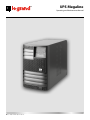
UPS Megaline
Operating and Maintenance Manual
Part. LE05744AA-08/12-01 GF
®
UPS Megaline
EN
2
ENGLISH
3
Index
1 Introduction
1.1 Important information
2 Funzionamento 2.1 Operating principle
4
4
5
5
2.2 Mains operation
6
2.3 Battery operation 6
2.4 By-pass operation 6
2.5 Information provided by the display 6
2.6 Visual and acoustic warning signals 7
3 Installation
3.1 Prior to installation 8
8
3.2 Where to install your UPS 8
3.3 Front panel 9
3.4 Installation procedure for a single cabinet UPS
3.5 Presetting for the expansion of autonomy 9
11
3.6 Installation procedure for a double cabinet UPS
12
3.7 Guide to using the diagnostics software
14
3.8 Operating procedures 14
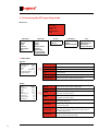
4 Customising the UPS operating mode
15
4.1 The functions of the buttons 15
4.2 The “Service Mode” function
15
4.3 Accessing menus 15
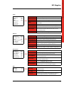
4.4 Ups status 16
4.5 Ups configuration 18
4.6 Events 22
4.7 Programming 23
4.8 Tools 24
5 Specifications
24
5.1 Construction specifications 24
5.2 Environmental specifications 25
5.3 Electrical input specifications 25
5.4 Output waveform
26
5.5 Electrical output specifications when running on mains power 26
5.6 Electrical output specifications when running on battery power 27
5.7 Battery operation 28
5.8 By-pass specifications
29
5.9 Reference standards
29
6 Troubleshooting
30
3
Operating and Maintenance Manual
UPS Megaline
®
1. Introduction
Thank you for choosing to purchase a LEGRAND® product. Our company’s main objective is to supply innovative products
that are the outcome of our ongoing research and application of cutting-edge technology.
Our products are covered by several international patents, emblematic of LEGRAND®’s quest for exclusivity and ongoing
improvement.
LEGRAND® uninterruptible power supplies are designed to protect electronic equipment from problems that may be
encountered with your mains electricity supply, such as power cuts, surges and interference.
In particular, the product you have purchased is enhanced with our exclusive “State of Charge Algorithm” which makes it
possible for your UPS to achieve the best possible performance in terms of autonomy.
Our products comply with international standards: an additional guarantee of the quality of our products.
We recommend you read this manual carefully and keep it for future reference.
1.1 Important information
• Do not connect loads in excess of the limit stipulated on the product’s label and in the relative documents provided.
• Do not dismantle the UPS. Only authorised technical personnel are allowed access to the internal parts of the UPS.
• Never disconnect the UPS from the mains power supply when it is running: this would cut off the earth protection of
both the UPS and of the loads connected to it.
• Do not insert screwdrivers or other items inside the ventilation holes or into the fan.
• The UPS must be installed according to the instructions in this manual and in compliance with the set limits.
• Take care that no liquids come into contact with your UPS.
• This product should only be employed for the designated uses described in this manual.
• The manufacturer is not liable for any damage or injury caused by failure to comply with the instructions in this manual.
All the information contained in this manual is provided as a guide and is subject to change without notice for
product upgrading.
4
2. Operation
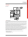
Block diagram
Output
By pass
~
Input
=
~
=
Input
Filter
Output
Filter
Power
Factor
Corrector
=
Inverter
Power
Module
=
Batteries
Voltage
Booster
Battery
Charger
Power Module
Batteries
Microprocessor
Logic
RS 232
Interface
Remote
Control
2.1 Operating principle
When the mains supply is present, the input voltage is filtered and rectified by a special input stage (power factor corrector)
which is able to optimise the absorption of current from the mains, so that the power factor becomes practically unitary,
and to compensate for any shifts in voltage. This stage is able to supply the output inverter even in conditions of very low
mains voltage.
This feature becomes very striking with very low loads: with a load of around 50% nominal load, mains operation is
possible as low as about 100 V without any exploitation of battery power. This enables more “intelligent” management of
the switchover to battery power, minimising use of the batteries. The voltage is rectified at the first stage and then taken
up by a high frequency inverter to produce the ‘clean’ sinusoidal output voltage, offering very low distortion rates.
A rapid, synchronised by-pass circuit intervenes during peaks of absorption above the inverter’s capacity, for example
when certain peripherals are switched on, demagnetisation of large colour monitors, etc.
Should the mains voltage fail or be subject to excessive sag, a booster stage is automatically activated.
This employs the batteries and safeguards the supply of power to the output inverter, and thus to the load, without any
break. The circuitry is a passing neutral type, i.e. with no alteration of the neutral system of the appliances connected to it.
During normal operation, a sensor verifies the difference in potential between the neutral wire and the earth wire: should
this be excessive, it will activate the input protection and switch the UPS over to battery mode, signalling the anomaly.
It is, however, possible to modify the parameters of the software so that only signalling is provided, if preferred.
All the UPS functions are supervised by a microprocessor that is also able to control and memorise certain operating
conditions, in addition to managing the UPS interface with a computer by means of a RS 232 serial line.
This makes it possible to control the operating functions and any anomalies in real time.
The UPS keeps the operator informed regarding its operating status using visual and acoustic signals:
- alphanumeric display 1 on page 9
- status indicator 7 on page 9
- acoustic signal (located inside the UPS)
5
Operating and Maintenance Manual
UPS Megaline
®
2. Operation
The combination of these signals enables rapid and intuitive understanding of its operating status and recognition of any
problems in the power supply.
There are three main operating modes
- Mains operation
- Battery operation
- By-pass operation
2.2 Mains operation
This is considered the normal operating condition:
- mains voltage is converted by the power factor corrector (PFC) into continuous current
- the inverter reconstructs the sinusoidal voltage from the continuous current
- the output filter provides extra “cleaning” of the output voltage
- the batteries are recharged
2.3 Battery operation
When there is a mains power failure, the UPS automatically switches over to battery mode.
- the voltage of the batteries is increased by the “booster” circuit
- the inverter reconstructs the sinusoidal voltage from the continuous current
- the output filter ensures the voltage supplied to the load is clean
2.4 By-pass operation
The by-pass circuit excludes the UPS and connects the output directly to the input. The switchover takes place in a
synchronised manner in order to ensure the correct output voltage is always guaranteed, preventing the risk of a break
in power or excess voltage.
The intervention of the by-pass circuit can be customised by means of a dedicated menu (Config. UPS, By-pass) which
provides many options (automatic, disabled, by-pass in load waiting mode, etc.) in order to meet the specific demands
of the application.
2.5 Information provided by the display
The main messages provided by the alphanumeric display in the three different operating modes are illustrated below.
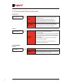
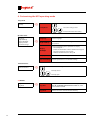
UPS on mains
UPS
On Mains
UPS switching on....
6
Indicates normal operating status, when mains voltage is present.
On Battery
Indicates that there is no mains power and the UPS is using its batteries
to supply power.
On By-pass
Indicates that by-pass operation has been turned on: the output of the
UPS is connected directly to the mains.
IN
xxxV
OUT
xxxV/x,xKW (xx%)
Batt.
xx,x?
Indicates the UPS input voltage and the RMS power absorbed by the
mains. This message is not displayed during battery operation.
The current power is also given as the percentage of the total power that
the UPS is able to supply.
Indicates the state of charge of the batteries in a chart format and the
autonomy available in a numeric format.
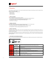
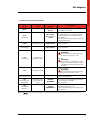
2.6 Visual and acoustic warning signals
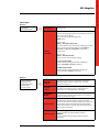
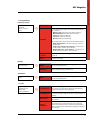
Status
indicator
Acoustic
signal
Messages
displayed
Green
-
UPS on Mains
IN xxxV
Normal operation with mains present and
loads within the set limits
The UPS is indicating that the frequency of
the output voltage is not synchronised with
the input voltage. The cause of this may be:
- PLL disabled
- Frequency of the input voltage is outside the
set limits for the UPS
Description
Green
Fast flashing
-
UPS on Mains
No sync mains
xx.xHz
Yellow
Short intermittent
sound (every 20sec)
UPS on Batteries
MAINS ABSENT
Battery operation
Yellow
Fast flashing
-
UPS on Bypass
By-pass operation
Module failure
ATTENTION!
We recommend you switch off the ups
and contact your service centre
Red
Fast flashing
Short and fast
intermittent sound
-
Overload
ATTENTION!
We recommend removing some of the
appliances connected to the ups so that
consumption by the load returns below
set limits
Red
Continuous sound
-
UPS error or failure
ATTENTION!
We recommend you switch off the ups
and contact your service centre
Red
1 flash every 10 secs.
-
-
Above 90% of MAX load
Red
Alternating short
long flashing
Alternating short,
long intermittent
sound
RESERVE
AUTONOMY!
Autonomy reserve. During battery operation
Incorrect battery connection
Incorrect Neutral
-
OUT OF
REDUNDANCY!
Consumption by the load is above the
redundancy that has been set.
Power board redundancy is not guaranteed in
case of failure
Red
Short flashing
with pause
NB: press
to silence the acoustic signal. The signal will be silenced or enabled each time this button is pressed.
7
Operating and Maintenance Manual
UPS Megaline
®
3. Installation
3.1 Prior to installation
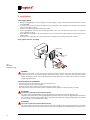
Check the packaging has not been opened or damaged and that the product has not been damaged during transport.
Please contact your shipping agent in case of doubt.
Check the contents of the box:
• Nr.1 UPS
• Nr.1 connector for the input/output cable (single cabinet version includes multiple output socket and input cable)
• Instructions manual
We recommend you keep the equipment’s packaging materials as they can be useful should the need arise to send the
product back for repairs.
3.2 Where to install your UPS
Make sure the place where you intend installing your UPS is level and sturdy.
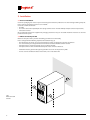
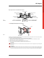
Please comply with the following requisites for installation (Fig. 1):
- The UPS must be located in an enclosed environment: it was not designed to operate out of doors.
- It is essential that you comply with the environmental conditions illustrated in this manual.
- Avoid placing it in very dusty or damp areas or in direct sunlight.
- Avoid places where there are inflammable liquids and/or corrosive substances.
- Ventilation must be guaranteed by placing the UPS at least 20 cm away from any walls
- Do not cover the ventilation outlets on the front, rear or sides of the UPS
Fig.1
Where to install
the UPS.
8
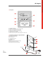
3.3 Front panel
1
2
3
4
5
6
7
Alphanumeric Display
ESC button / exit function / silence acoustic signal
Button to scroll backwards / increase value
Button to scroll forwards / decrease value
Enter button / confirm function / access menu
Button to switch on / switch off
Multicolour operating status indicator light (green / yellow / red)
3.4 Installation procedure for a single cabinet UPS
3.4.1 Electrical connections
Single Cabinet (fig. 2):
8 Input/Output connector
9 Input/Output plug
10 Input fuse
11 RS232 serial interface outlet (9-pin female)
12 Logic signals outlet ( 9-pin male)
13 Presetting for expansion of autonomy
To the loads
Fig.2
Electrical
Connections.
To the mains
electricity
supply
9
Operating and Maintenance Manual
UPS Megaline
®
3. Installation
3.4.2 Single cabinet
1. Wire up the Input-Output connector supplied as shown in figure 3, using insulated cable with wires whose section is
at least 2.5 mm2.
2. Insert the connector into the plastic housing and secure it using the screws supplied. Secure the wires to the housing
using the cable grip (see fig. 3).
3. Take the cover off the plug [9] by removing its screws.
4. Put the Input-Output connector into the plug [9] located on the rear of the UPS, and secure to its case using the
screws supplied (see fig. 2).
5. Check that the on/off switches of all the appliances to be connected to the UPS are OFF and connect them to the
output socket.
6. Insert the power supply plug into a power outlet that is adequate for the voltage and current required.
Input-output connector - Assembly
Connector
Reference
notch
Plastic housing
Fig. 3
Connection
terminals housing.
Cable grip
WARNING
Your UPS is fitted with a circuit to protect it against the risk of incorrect connections. This eventuality will be
indicated by means of its red warning light, lit without flashing, and the continuous sounding of its internal
buzzer. Should you note this signal immediately after switching the UPS on, switch it off and remove the power
supply plug immediately.
3.4.3 Precautions for installation
• Electrical connections should only be done by trained personnel
• Do not modify the electric cables supplied
• Make sure that the mains outlet is connected securely to an earth circuit
• The mains outlet, or the circuit breaker, must be installed near the appliance and must be easily accessible
10
ATTENTION
(for versions 3 103 46/3 103 47/3 103 48/3 103 49)
The cables supplied are fitted with an input plug and outlet sockets whose maximum capacity is 16A.
Therefore, we recommend use of direct cabling from the control panel to the connector supplied (follow instructions
for connections shown in Figs. 3 andEarth
4 on connection
Page 11) for applications where the anticipated UPS input current will be
in excess
of
13A
(e.g.
5000
VA
with
Vinn=184V)
Yellow-green wire
Yellow-green wire
Blue wire
ATTENTION Brown wire
wire 103 47/3 103 48/3 103 49)
Brown wire
(for versions 3 Blue
103 46/3
Since current dispersion towards earth
of
all
the
loads
merges
in
the
UPS protection wire (earth wire), it is essential to
4
1
cable
check
thatcable
the sum of these currents does not exceed 2.7 mA, according toInput
standard
EN 62040-1, for safety reasons.
Output
(to
the
mains
5
2
(to load)
electricity supply)
3
6
Terminal n°1 PHASE OUTPUT
Terminal n°2 NEUTRAL OUTPUT
Terminal n°4 NEUTRAL OUTPUT
Terminal n°5 PHASE OUTPUT
Input-output connector - Side with insertion of wires
Earth connection
Yellow-green wire
Yellow-green wire
Brown wire
Blue wire
Blue wire
Output cable
(to load)
Brown wire
1
4
2
5
3
6
Terminal n°1 PHASE OUTPUT
Terminal n°2 NEUTRAL OUTPUT
Fig. 4
Terminals.
Input cable
(to the mains
electricity supply)
Terminal n°4 NEUTRAL OUTPUT
Terminal n°5 PHASE OUTPUT
3.5 Presetting for the expansion of autonomy
Fig. 5.
nverter Cabinet
Your UPS is complete with presetting for the connection of additional battery cabinets. One or more extra battery cabinets
can be fitted to a single cabinet UPS as follows:
1. Loosen screws 1 and 2 shown in figure 5, but do not unscrew them completely.
2. Slide the protective casing to the left so that the connectors located inside the box are completely accessible.
3. Tighten the screws to secure the metal protection.
4. Connect the battery cabinet to the UPS using the dedicated cables.
5. Use the plaited conductor supplied to safeguard a good contact with earth.
ATTENTION
Make sure the UPS has been switched off and disconnected from the mains supply before proceeding with
connections.
Battery connections
ATTENTION
The cables supplied with the battery cabinet were designed for connection to the UPS cabinet of double cabinet
UPS versions (3 103 60, 3 103 63, 3 103 66, 3 103 69, 3 103 72): in this case, all three cables supplied must be
connected. For single cabinet versions (3 103 46, 3 103 47, 3 103 48, 3 103 49) use only 2 of the 3 cables supplied.
Battery Cabinet
Brass washer
Copper braid
Brass washer
Grower washer
Nut
11
Operating and Maintenance Manual
UPS Megaline
®
3. Installation
3.6 Installation procedure for a double cabinet UPS
Double Cabinet (fig. 6):
8 Battery connections
9 Input/Output plug
10 Mains fuses
11 RS232 serial interface outlet (9-pin female)
12 Logic signals outlet ( 9-pin male)
13 Copper plaited conductor
3.6.1 Double Cabinet.
The following connections are located on the rear of the UPS:
Inverter Cabinet
• Input-Output Plug [9]: connect the previously wired connector supplied in the bag of accessories to this plug.
• Outlet for connection of RS232 type computer serial interface (9-pin female) [11]: this is used if you want to use the
diagnostics or shutdown software.
• Two sockets for connection of a remote control and logic signals computer interface (9-pin male) [12]: for use with the
relative devices (optional).
• Output for Battery Cabinet connection cables [8].
• Screw for earth connection of battery cabinet [14].
Battery Cabinet
• Connector for connection to the Inverter Cabinet using the cables supplied [8].
• Screw for earth connection of case [14].
Follow the steps below for installation:
1. Looking at the UPS from the front, put the Battery Cabinet to the left of the Inverter Cabinet; also check that the
ventilation holes are not blocked.
2. Connect the earth between the two cabinets using the copper plaited conductor supplied, as shown in fig.6.
3. Connect the Battery Cabinet using the cables supplied (there should be no remaining free connectors: use all the
cables supplied).
4. Wire up the Input-Output connector supplied as shown in figure 8, using insulated cable with wires whose section is
at least 4 mm2.
5. Insert the connector into the plastic housing and secure using the screws supplied. Insert the wires into the appropriate
holes and secure them using the two cable grips (see fig. 7).
6. Take the cover off the plug [9] by removing its screws.
7. Put the Input-Output connector into the plug [9] located on the rear of the UPS, and secure to its case using the
screws supplied (see fig. 6).
8. Check that the on/off switches of all the appliances to be connected to the UPS are OFF and connect them to the
output socket.
9. Insert the power supply plug into a power outlet that is adequate for the voltage and current required.
WARNING
Never remove the 230 V power plug whilst the UPS is in operation: this would disconnect the earth protection of
both the UPS and of the connected loads.
ATTENTION
(for versions 3 103 60; 3 103 63; 3 103 66; 3 103 69; 3 103 72)
Since current dispersion of all the loads towards earth merge in the UPS protection wire (earth wire), it is essential to
check that the sum of these currents does not exceed 2.7 mA, according to standard EN 62040-1, for safety reasons.
12
WARNING
Your UPS is fitted with a circuit to protect it against the risk of incorrect connections. This eventuality will be
indicated by means of its red warning light, lit without flashing, and the continuous sounding of its internal buzzer.
Should you note this signal immediately after switching the UPS on, switch it off and remove the power supply plug
immediately.
Connector
Battery connections
Inverter Cabinet
Battery Cabinet
Cable grips
Brass washer
Copper braid
Plastic
Brass washer
housing
Grower washer
Nut
POWER supply input
(from mains electricity)
EEC 2P+E EEC
Standard plug
2P+E EEC
Standard socket
with disconnecting
switch and fuses (32 A)
Cable grips
Screw cable grips
clockwise to secure cables
Fig. 6.
Output for loads
(protected by UPS)
EEC 2P + E EEC
Standard socket
Terminal n°1
NEUTRAL OUTPUT
Terminal n°2
PHASE INPUT
Brown wire
Blue wire
Connector
Yellow-green wire
1
Fig. 7.
Housing of
double cabinet
connection
terminals.
Fig. 8.
Double cabinet
connection
terminals.
Earth
connection
12
11
3
Cable grips
2
4
Blue wire
Brown wire
Yellow-green wire
Plastic
housing
Terminal n°3
PHASE OUTPUT
Terminal n°4
NEUTRAL INPUT
13
Operating and Maintenance Manual
UPS Megaline
®
3. Installation
3.7 Guide to using the diagnostics software
3.7.1 Connection
Your UPS is fitted with a standard RS232 interface, which can be used in conjunction with a computer in order to access
data relating to the operation of the UPS and its log. This function must be used together with the interface programme
for WINDOWS environments available from our website www.ups.legrand.com without charge. A RS232 cable is required
to connect a serial port on your PC to the interface outlet [11] located on the rear of the UPS.
3.8 Operating Procedures
Switch on
UPS
on
Press
button
mains
Switch off
During operation (example)
UPS on mains
The display reads
UPS switching on....
Press button for a few seconds
UPS switching on....
The status indicator shows the sequence during switch
on (red, yellow, green).
The display shows the operating status (example).
UPS on mains
UPS switching on....
14
The acoustic warning signal sounds repeatedly then the
UPS switches off (5 seconds).
4. Customising the UPS operating mode
4.1 The functions of the buttons
The buttons on the front panel of the UPS are used to access its various menus.
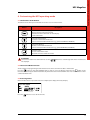
Button
Description
- Exit a function without modifying it
- Go up a level to an upper level menu
- Exit the main menu and return to status display
- Silence the buzzer
- Select previous function
- Increase a value within the function
- Select a new item within the function (e.g. go from DISABLED to ENABLED)
- Select next function
- Reduce a value within the function
- Select a new item within the function (e.g. go from ENABLED to DISABLED)
- Confirm a value
- Access an item in the menu
- Go down a level to a lower level menu
ATTENTION:
Some menus contain more than four lines: use the
not displayed.
buttons to scroll through items in the menu that are
4.2 The “Service Mode” Function
All the settings and programming described below can be done even when the UPS is switched off.
Press the
button to enter UPS “SERVICE” mode in order to access the Display menu. Press the
button to exit
this mode. Alternatively, the UPS will automatically exit the function and switch off if it does not receive manual or serial
commands within 1 min.
4.3 Accessing menus
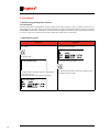
When the UPS switch on procedure has been completed, the display will read (example).
UPS on mains
Press the
button to access the main menu.
UPS switching on....
15
Operating and Maintenance Manual
UPS Megaline
®
4. Customising the UPS operating mode
Main menu
UPS Status
UPS Config.
Events
Programming
Tools
UPS Status
UPS Setup
Output
Input
Bypass
Neutral Sensor
Batteries
Clock setup
Operator Panel
Contact Interface
UPS Info
Output
Input
Batteries
History Data
Misc.
Events
log View
log Reset
Scheduling
Tools
Schedule Planning
Restart
Shutdown Planning
Signalling Test
LCD Display Test
Battery Test
Battery Calibration
4.4 ups Status
UPS Info
Mod Megaline xxxx
POut Max xxxx
SWVer. xxxx
S/N xxxxxxxxx
Installed Modules x
Faulty Modules x
ð
Mod
Indicates the name of the UPS
POut max
Indicates the potential maximum active power (W)
SWVer.
Software version
S/N
Serial number
Installed Modules
Number of power modules fitted
Faulty Modules
Number of power modules that have failed
Power
Indicates the active power supplied (W)
Appar. Pow.
Indicates the apparent power supplied (VA)
V RMS
Indicates the effective voltage (V RMS)
supplied at the UPS output
I RMS
Indicates the effective current (A RMS)
supplied at the UPS output
Peak current
Indicates the peak current supplied
at the UPS output (A)
Frequency
Indicates the frequency of the UPS
output voltage (Hz)
I Crest factor
Indicates the crest factor, calculated as the ratio between
the peak value and the effective value of the current
absorbed by the load
Power fact.
Indicates the power factor
for the load connected to the UPS
Output
Power Appar.Pow. V RMS I RMS Peak current Frequency I Crest factor Power fact. 16
xxxxx
xxxx
xxxx
xxxx
xx
xx
xx
xx
ð
Input
Power Appar.Pow. V RMS I RMS Peak Current Frequency I Crest factor Power Fact xxxx
xxxx
xxx
xxxx
x
x
x
x
ð
Power
Indicates the power received from mains (W)
Appar.Pow.
Indicates the apparent power received from mains (VA)
V RMS
Indicates the effective voltage (V RMS) at the UPS input
I RMS
Indicates the effective current (A RMS) received
from mains
Peak Current
Indicates the peak current received from mains (A)
Frequency
Indicates the frequency of the UPS input voltage (Hz)
I Crest factor
Indicates the crest factor, calculated as the ratio between
the peak value and the effective value of the current
received from mains
Power Fact
Indicates the power factor applied to mains
Voltage
Indicates the voltage at the terminals of the battery kits (V)
Residual Cap.
Indicates the percentage of battery charge
Discharge count
Indicates the number of battery discharge cycles
Usage
Hours of operation on battery power
Cal.
Indicates the date (day / month / year) and the time
(hours / minutes) of the last battery calibration
Ext. KB units
Indicates the number of external KBs fitted
Ext Chargers
Indicates the number of external battery chargers fitted
UPS Ontime
Indicates the total number of hours of UPS operation
BoosterOnTime
Indicates the number of hours of UPS operation
in booster mode (running on battery power)
DrainedOut N.
Indicates the number of times the UPS has completely
discharged its batteries
Booster Int.
Number of times booster mode has intervened
(running on battery power)
Bypass Interv.
Number of times the by-pass has intervened
(refer to Config.UPS / By-pass menu)
OverheatCount
Number of times the thermal protection has been
triggered (due to excessive load, for example)
Int. Temp.
Indicates the internal temperature of the UPS,
shown in Celsius
Ext. Temp.
Indicates the external temperature of the UPS,
shown in Celsius
Fan speed
Indicates the speed of the UPS cooling fans, shown in
a percentage format (100% = maximum speed)
Batteries
Voltage xx
Residual Cap. xxxx
Discharge count xxxx
Usage xxxx
Cal.dd/mm/yyhh:mm
Ext. KB units xx
Ext Chargers xx
ð
History Data
UPS Ontime BoosterOnTime DrainedOut N. Booster Int. Bypass Interv. OverheatCount xxxxx
xxxx
xxxx
xxxx
xxxx
xxxx
ð
Misc.
Int. Temp. Ext. Temp. Fan speed xx
xx
xx
ð
17
Operating and Maintenance Manual
UPS Megaline
®
4. Customising the UPS operating mode
4.5 UPS Setup
Output
Voltage
Frequency
N+x Redundancy
ð
Voltage
To set the UPS output voltage (V)
To set the UPS output frequency (Hz)
Nominal Value: to set a numerical value for the output
frequency (50 or 60)
Frequency
Auto Selection:
If enabled, the UPS reads the frequency of the input
voltage and then synchronises the output to the same
value.
If disabled, the UPS uses the set Nominal Value.
N+x
Redundancy
To set the number of redundant boards
(refer to NB: Redundancy Settings)
NB: Redundancy Settings
This function is used to manage the redundancy of the power modules. For example: a load requires N power modules; X power
modules must be added to achieve N+X redundancy.
If the load applied exceeds the power supplied by N modules during operation, the UPS will signal the lack of redundancy
A numerical example is given below:
Load
Power
boards
Total
power (W)
Redundancy
Redundancy
alarm (W)
Overload
alarm (W)
3700
3
3750
0
no
3750
3700
4
5000
1
3750
5000
1500
4
5000
2
2500
5000
1000
4
5000
3
1250
5000
Input
PLL Enable
Extended PLL Range
ð
PLL Enable
If enabled, the UPS synchronises the output sine wave
with the input If disabled, the output voltage is not
synchronised with the input.
This is indicated by the flashing of the status
warning light (green)
Extended
PLL Range
If enabled, the UPS synchronises the output voltage with
the input for variations in frequency of +/-14% the
nominal value. If disabled, the PLL is synchronised for
variations in frequency of +/-2%.
NB: PLL Settings.
The PLL function ensures the UPS output frequency is synchronised with the input so that the changeover at zero takes
place at the exact same time. Should the by-pass intervene, e.g. due to unanticipated loads, input-output synchronisation
is guaranteed.
18
ATTENTION
If the PLL function is disabled, the automatic by-pass function is also disabled.
Should the variation in input frequency be above the set range, the UPS will inhibit the PLL function and release
the output and input lock. When the range returns within the set threshold, the PLL function will be reinstated
automatically.
By-pass
Bypass Enable
Forced mode
DIP Speed
Off-line mode
Load Wait Mode
ð
Bypass Enable
If enabled, the UPS manages by-pass intervention
automatically.
If disabled, the UPS will never switchover to by-pass
operation. The UPS will switch off in cases of lengthy
overload.
Forced mode
If enabled, the UPS enters permanent by-pass operation.
DIP Speed
This is to alter the sensitivity of the automatic intervention
by the by-pass (when forced mode is disabled)
SLOW: for loads that are not sensitive to dips in voltage
or micro breaks but that cause frequent peaks.
STANDARD: normal use
FAST: loads sensitive to micro breaks
Off-line mode
If enabled, the by-pass operates as follows:
- When mains power is present, the UPS runs
permanently in by-pass mode
- Should mains power fail, the UPS enters battery mode.
Load Wait Mode
ENABLE: switches the function on or off
If enabled, the by-pass enters operation when the load is
below the threshold set for “Minimum load threshold”
Above this threshold, the by-pass stops working.
Minimum load threshold: to set the value for the load for
the switching on and off function (refer to NB: Load
Waiting without mains power).
NB: Load Waiting without mains power.
In “Load Waiting” mode, the UPS will switch the by-pass on when the load is below the set threshold. Should there be no
mains power, the UPS will switch off and only switch on again when mains power is restored.
ATTENTION!
Programming priority is as follows:
Operational
function
Enable
By-pass
Forced
Mode
Off-line
Mode
Load
Waiting
Forced mode
ENABLED
ENABLED
X
X
Off-line mode
ENABLED
DISABLED
ENABLED
ENABLED
Off-line mode
ENABLED
DISABLED
ENABLED
DISABLED
Load waiting mode
ENABLED
DISABLED
DISABLED
ENABLED
Automatic mode
ENABLED
DISABLED
DISABLED
DISABLED
By-pass disabled
DISABLED
X
X
X
X: either setting (ENABLED or DISABLED).
19
Operating and Maintenance Manual
UPS Megaline
®
4. Customising the UPS operating mode
Neutral Sensor
Enable
Ignore While Run
ð
Enable
If enabled, the UPS uses the neutral sensor to verify that
the difference in voltage between neutral and earth is
within safety limits.
Should it go above the threshold, the UPS will
automatically switchover and run on battery mode.
If disabled, the UPS will ignore the neutral sensor.
Ignore While
Run
If enabled, the UPS only verifies neutral-earth voltage
when it is switched on. If disabled, the UPS will verify
neutralearth voltage in all operating conditions.
Batteries
Capacity Manag.
ð
Capacity
Manag.
There are two options for programming
ADVANCED MODE
The warning signal for the end of autonomy is determined
by reading the power absorbed by the load connected to
the UPS and is displayed as the remaining autonomy time
SIMPLE MODE
The warning for the end of autonomy is calculated by
reading the battery voltage.
The chosen setting determines the type of battery
programming menu displayed.
ADVANCED MODE
Batteries
Set capacity
Reserve Time
20
ð
Set capacity
Advanced mode
Reserve
Time
Sets the warning signal for the end of battery autonomy
using the remaining run time (minutes)
SIMPLE MODE
Batteries
Set capacity
Battery Thresholds
ð
Set capacity
Simple mode
Sets the warning signal for the end of battery autonomy
using the battery voltage.
There are two possible settings in the
Mode menu
Battery
thresholds
If you select
Mode – Automatic thresholds
The UPS automatically calculates the voltage thresholds
based on the load: the UPS will signal AUTONOMY
RESERVE and END OF AUTONOMY, respectively,
below these.
If you select
Mode – Fixed thresholds
There are two options for this setting:
1) Reserve threshold
Sets the battery voltage threshold; the UPS will
signal AUTONOMY RESERVE below this
2) Exhaust threshold.
Sets the battery voltage threshold; the UPS will
signal END OF AUTONOMY below this.
Batteries
Max Time On Batt.
Max time reserve
TurnOn Test Enable
Restart Enable
External options
ð
Max Time
On Batt.
Sets the maximum time for continuous operation in
BATTERY mode, shown in seconds. If “0” is set, this
function is disabled.
Max time
reserve
Sets the maximum time for operation in BATTERY mode
after the reserve limit has been reached, shown in
seconds. If “0” is set, this function is disabled.
TurnOn Test
Enable
If enabled, the batteries are tested each time the UPS
is switched on. If disabled, the batteries are not tested
when it is switched on again.
Restart Enable
If enabled, the UPS will switch on again when mains
power is restored after switching off due to the end of its
autonomy. If disabled, the UPS will not switch back on
when mains power is restored after switching off due to
the end of its autonomy.
External options
Battery Chargers N°
Sets the number of external battery chargers
KB Units
Sets the number of packs of three batteries fitted
externally
21
Operating and Maintenance Manual
UPS Megaline
®
4. Customising the UPS operating mode
Setup Clock
23/06/03 -19:25:06
Monday
ð
Sets the time and date
Setup Clock
Select the setting to alter
Increases/Decreases the setting
Operator Panel
Language
Keyboard Beep
Display Backlight
Display contrast
Password Change
ð
Language
Set the language
Keyboard Beep
Enables or disables the acoustic signal when buttons
are pressed
Display
Backlight
Set the backlighting of the alphanumeric display
- Fixed: always lit
- Timed: the illumination switches off when the keypad
has been inactive for a few seconds
- Disabled: the illumination is always off
Display contrast
Sets the contrast of the display
Password Change Sets the password to access the UPS settings
Contact Interface
Contact Interface
ð
It allows the setting of contacts
normally closed
normally open
4.6 Events
Log View
Log Reset
22
ð
Log View
Displays the events stored in the UPS memory, for example
END OF AUTONOMY, OVERHEATING ALARMS etc.. with
relative TIME and DATE
Log Reset
Deletes the events stored in the UPS memory
4.7 Programming
Planning Schedule
Enable
View/Edit
Sched. sequence
Reset
ð
Enable
View/Edit
To enable or disable set programmes
To set and modify programmes. The following functions
are available:
- Batteries Test (verifies the status of the batteries)
- Batt. Calibration (calibration of the batteries)
- Turn on (to switch the UPS on)
- Turn off (to switch the UPS off )
- Absent (disables programming)
Each programme can be executed in the following ways:
- Daily “hour-minutes”: executed every day at the set
hourminutes;
- Single “day –month –hour -minutes”: executed once
on the set “day –month –hour -minutes”
- Weekly “day name –hour -minutes” : executed every
week on the set “day name –hour -minutes”.
Sched.
sequence
Used to display all the set programmes in the daily order
(max 16)
Reset
Deletes all settings
ð
Delay
Duration, in seconds, of the warning signal that the UPS
is about to switch back on
Min.
Autonomy
Percentage of battery charge below which the UPS
will not automatically switch back on
ð
Delay
Duration, in seconds, of the warning signal that the UPS
is about to switch back on
Segnalling Test
Tests the warning lights. Press the ENTER button to
execute the test of the Green, Yellow and Red warning
lights and the Acoustic warning signal.
LCD Display Test
Tests the alphanumeric display. Press the ENTER button
and all the available digits are shown on the alphanumeric
display.
Battery Test
Tests the batteries. Contact your Service Centre in case
of problems.
Battery
Calibration
Calibrates the batteries, calculating the discharge curve for
the batteries. We recommend this cycle be carried out
when the batteries have been changed so that the UPS is
able to provide precise information regarding the status of
their charge.
Restart
Delay
Min. autonomy
Shutdown
Delay
4.8 Tools
Segnalling Test
LCD Display Test
Battery Test
Battery Calibration
ð
23
Operating and Maintenance Manual
UPS Megaline
®
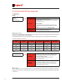
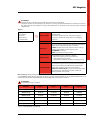
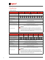
5. Specifications
5.1 Construction specifications
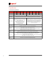
3 103 46 3 103 47 3 103 48 3 103 49 3 103 60 3 103 63 3 103 66 3 103 69 3 103 72
Weight (Kg.)
Size (LxHxP)
Technology
Expandability
Expandability
Computer
Interface
Remote
control
Protection
Synchronised
By-pass
24
23,5
34
43
53
270 x 475 x 570 mm
24+50
26,5+ 57,5
29+65
31,5+72,5
34+80
270 x 475 x 570 mm x 2 cabinets
PWM high frequency both for input stage and output stage. Microprocessor control logic
Optional upgrading to configurations with
higher power by fitting one or more extra
power modules inside the same cabinet,
up to a maximum of 4.
Optional upgrading of autonomy
by fitting extra batteries inside,
up to a maximum of 4 sets
of 3, 12V, 9Ah batteries.
Optional upgrading to configurations with higher
power by fitting one or more extra power modules
inside the same cabinet, up to a maximum of 8.
Optional upgrading of autonomy by fitting extra
batteries inside, up to a maximum of 10 sets
of 3, 12V, 9Ah batteries.
For greater autonomies, optional battery cabinets can be connected,
each with a capacity of max 10 sets of 3, 12V, 9Ah batteries.
With logic levels, to interface with optional kits.
Output with 9-pin male, SELV insulated connector.
Standard serial RS232 for interfacing with personal computer using diagnostics software.
Output with 9-pin, female, SELV insulated, connector.
Output with 9-pin male, SELV insulated connector for connection to optional remote control.
Optional scheduling of UPS switch on/off and display of main UPS signals.
Electronic protection against overloads, short circuits and excessive battery discharge.
Operation blocked at end of autonomy. Inrush limitation when switching on.
Sensor for correct neutral connection.
Back-feed protection (electrical insulation for the safety of the input plug when running in battery
mode). EPO contact (emergency power off )
Automatic static and manual (optional).
Intervenes in case of overload and operating anomaly.
5.2 Environmental specifications
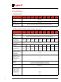
3 103 46 3 103 47 3 103 48 3 103 49 3 103 60 3 103 63 3 103 66 3 103 69 3 103 72
Maximum altitude
for storage
10.000 metres
Storage temperature
range
from -20° C to +50° C
Operating
temperature range
from 0° C to +40° C
Range of relative
humidity for operating
20-80% non condensing
Grade of protection
(IEC529)
IP 21
Noise level
at 1 metre
(<) 40dB A
5.3 Electrical input specifications
3 103 46 3 103 47 3 103 48 3 103 49 3 103 60 3 103 63 3 103 66 3 103 69 3 103 72
Nominal input voltage
Input voltage range
230 V
from 184V to 264V with nom. load – from 100V to 264V with 50% of nom. load
Nominal input
frequency
50 Hz or 60 Hz +/-2% (autosensing and/or as selected by operator)
Nominal input
current
4,6A rms
Maximum input
current
5,75A rms 11,2A rms 16,6A rms 22,2A rms 22,2A rms 27,8 rms 33,25A rms 38,9A rms 44,5A rms
8,9A rms 13,2A rms 17,7A rms 17,7A rms 22,4A rms 26,9A rms 31,25A rms 36,6A rms
Distortion of input
current
THD < 3%
Input power factor
> 0,99 dal 20% of nominal load
Number of input
phases
100% of nominal current
In-rush current
Line fuse
Battery charger
directly from mains
Single phase
25 AFF
32 + 32 AFF
0,8 A rms
25
Operating and Maintenance Manual
UPS Megaline
®
5. Specifications
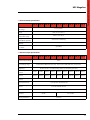
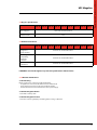
5.4 Output wave form
3 103 46 3 103 47 3 103 48 3 103 49 3 103 60 3 103 63 3 103 66 3 103 69 3 103 72
With mains
operation
Sine wave
With battery
operation
Sine wave
Type of operation
No break, on line UPS with passing neutral and double conversion
5.5 Electrical output specifications when running on mains power
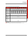
3 103 46 3 103 47 3 103 48 3 103 49 3 103 60 3 103 63 3 103 66 3 103 69 3 103 72
Nominal output
voltage
230 V ± 1%
Nominal output
frequency
50 Hz / 60Hz synchronised (autosensing and/or as selected by operator)
Output current with
linear load and
power factor 0,7
5,37A
rms
10,75A
rms
16,25A
rms
21,6A
rms
Crest factor on
output current
Nominal output
power VA
Active output power
with linear or
nonlinear load P.F. 0,7
38A
rms
43,5A
rms
2500VA
3750VA
5000VA
5000VA
6250VA
7500VA
8750VA 10000VA
875W
1750W
2625W
3500W
3500W
4375W
5250W
6125W
Total harmonic
distortion of output
voltage with
nominal non-linear
load P.F.0,7
< 1%
AC-AC conversion
efficiency with linear
load PF = 1 and
charged batteries:
• with 50% load
• with 75% load
• with 100% load
32,6A
rms
1250VA
< 0,5%
Number of output
phases
27,2A
rms
3,5
Total harmonic
distortion of output
voltage with
nominal load
Overload
capacity
26
21,6A
rms
300% for 1 second without By-pass intervention
200% for 5 seconds without By-pass intervention
150% for 30 seconds without By-pass intervention
Single phase
80%
85%
92%
7000W
5.6 Electrical output specifications when running on battery power
3 103 46 3 103 47 3 103 48 3 103 49 3 103 60 3 103 63 3 103 66 3 103 69 3 103 72
Nominal output
voltage
230 V ± 1%
Output
frequency
Nominal output
power VA
Active output power
with linear or
nonlinear load P.F. 0,7
Total harmonic
distortion of output
voltage
Overload
capacity
Tolerated power
factor range of
applied load
DC-AC conversion
efficiency with
linear load P.F. 1 and
charged batteries:
• with 50% load
• with 75% load
• with 100% load
50 Hz / 60Hz ± 1% (autosensing and/or as selected by operator)
1250VA
2500VA
3750VA
5000VA
5000VA
6250VA
7500VA
8750VA 10000VA
875W
1750W
2625W
3500W
3500W
4375W
5250W
6125W
7000W
< 1%
160% impusive
from 0,7 to 1
80%
80%
80%
ATTENTION:
There is a danger of explosion should the batteries be replaced with the wrong type.
Dispose of used batteries as per the instructions and precautions for their disposal on the battery label!
27
Operating and Maintenance Manual
UPS Megaline
®
5. Specifications
5.7 Battery operation
3 103 46
3 103 47
Approximate autonomy in
minutes with charged batteries
Percentage of applied load
3 103 48
3 103 49
230 V ± 1%
50%
Standard UPS
20
80% 100% 50%
11
8
80% 100% 50%
20
Recharge time up to
90% of total charge
11
8
20
80% 100% 50%
11
8
80% 100%
20
11
8
5 - 6 hours according to level of discharge
Specifications and quantity
of batteries
n. 3 pcs 12V 9Ah, sealed, lead-acid, maintenance free batteries connected in series
for each power module
Reserve signals
from 32.2 V to 36V, can be programmed by operator
Minimum voltage for battery
operation during discharge
from 27V to 31.5V with automatic selection depending on applied load,
or as programmed by operator
3-6 years according to use and working temperature
Average battery life
Warning!
The batteries in the UPS are subject to a reduction in capacity depending
on their age (a feature of lead batteries declared by their manufacturer in
the technical manual). For example, the reduction of capacity of a 4-year-old
battery can be as much as 40%, resulting in a proportional reduction of UPS
autonomy time when running on battery power.
3 103 60
3 103 63
3 103 66
3 103 69
3 103 72
Approximate autonomy in
minutes with charged batteries
Percentage of applied load
Standard UPS
50% 80% 100% 50% 80% 100% 50% 80% 100% 50% 80% 100% 50% 80% 100%
20
Recharge time up to
90% of total charge
11
8
20
11
8
20
11
8
20
11
8
20
11
8
5 - 6 hours according to level of discharge
Specifications and quantity
of batteries
n. 3 pcs 12V 9Ah, sealed, lead-acid, maintenance free batteries
connected in series for each power module
Reserve signals
from 32.2 V to 36V, can be programmed by operator
Minimum voltage for battery
operation during discharge
from 27V to 31.5V with automatic selection depending on applied load or as
programmed by operator
3-6 years according to use and working temperature.
Average battery life
28
Warning!
The batteries in the UPS are subject to a reduction in capacity depending
on their age (a feature of lead batteries declared by their manufacturer in
the technical manual). For example, the reduction of capacity of a 4-year-old
battery can be as much as 40%, resulting in a proportional reduction of UPS
autonomy time when running on battery power.
5.8 By-pass Specifications
3 103 46 3 103 47 3 103 48 3 103 49 3 103 60 3 103 63 3 103 66 3 103 69 3 103 72
Type of by-pass
Static and electromechanical
Switchover time
zero
5.9 Reference Standards
3 103 46 3 103 47 3 103 48 3 103 49 3 103 60 3 103 63 3 103 66 3 103 69 3 103 72
Safety:
Designed to
satisfy standard
Conforms to standard EN 62040-1
Electromagnetic
compatibility:
• immunity
• emission
Conforms to standard EN 62040-2
Typical
performance
Conforms to standard EN 62040-3
LEGRAND® reserves the right to vary data and specifications without notice
5.10 Routine maintenance
5.10.1 Cleaning
Before cleaning, it is essential to verify the following:
- all appliances connected to the UPS have been switched off
- all the appliances have been disconnected from the UPS
- the UPS has been disconnected from the mains power supply
5.10.2 Cleaning the cabinet
- Clean with a soft dry cloth
5.10.3 Cleaning the air vents
- Clean the air vents regularly by vacuuming them or using a soft brush
29
Operating and Maintenance Manual
UPS Megaline
®
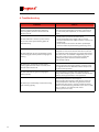
6. Troubleshooting
Problems
30
Solutions
When the UPS is switched on, the buzzer sounds
and the red warning light makes alternating
short-long flashes, then the UPS switches off
after 15 seconds.
The connection of the neutral conductor is wrong:
invert the power supply plug, or invert the connections of
the neutral and phase input leads, or exclude the neutral
sensor.
The UPS works but a short beep is heard every
12 seconds and the yellow warning light is lit
without flashing.
- Check power is present at the mains outlet.
- Check that the UPS power supply cable is correctly
inserted in both the mains outlet and in the connector on
the UPS itself.
- Check the fuse located at the side of the input/output
connector under the plastic housing (refer to fig.1 or 4)
The UPS works but it beeps intermittently and the
red warning light and the yellow warning light are
flashing.
There is an overload on the UPS output. Reduce the quantity
of appliances connected so that the load does not exceed
the maximum power that the UPS can supply. Alternatively,
if the UPS is not in its maximum configuration, you can ask
your Service Centre to increase the power of your UPS
by fitting extra power boards and relative batteries
inside the UPS cabinet.
The UPS beeps continuously and the yellow
warning light flashes for about 15 seconds, after
which the UPS switches off.
The UPS has completely flattened its batteries; it can only
start up again when the mains input line is present. Check
the magneto-thermal or differential switches that precede
the UPS and the input fuse
The UPS works but the green warning light is
flashing quickly.
The mains supply is out of the limits permitted for the
voltage and/or frequency, but it can still be used by the UPS.
However, the by-pass function is not operational.
The UPS beeps intermittently and the red warning
light is flashing quickly.
The thermal protection has been tripped.
Switch the UPS off and wait for a few minutes so that the
internal temperature of the UPS can get back to normal.
Check that the fans operate correctly and that the relative
airflow is not obstructed (e.g. if the UPS is too close to a wall).
There is a fault on one of the internal circuits.
Contact your service centre.
®
World Headquarters and
International Department
87045 LIMOGES CEDEX FRANCE
: 33 5 55 06 87 87
Fax : 33 5 55 06 74 55
www.legrandelectric.com
Installer stamp
Legrand reserves at any time the right to modify the contents of this booklet and to communicate,
in any form and modality, the changes brought to the same.