1
S60 Quick Start Guide
FTOS version 8.3.3.1
July 30, 2010
Copyright 2010 Force10 Networks
All rights reserved. Printed in the USA. January 2010.
Force10 Networks® reserves the right to change, modify, revise this publication without notice.
Trademarks
Force10 Networks® and E-Series® are registered trademarks of Force10 Networks, Inc. Force10, the Force10 logo, E1200, E600, E600i,
E300, EtherScale, TeraScale, FTOS, C-Series, and S-Series are trademarks of Force10 Networks, Inc. All other brand and product names are
registered trademarks or trademarks of their respective holders.
Statement of Conditions
In the interest of improving internal design, operational function, and/or reliability, Force10 Networks reserves the right to make changes to
products described in this document without notice. Force10 Networks does not assume any liability that may occur due to the use or
application of the product(s) described herein.
Table of Contents
Chapter 1
S60 Overview . . . . . . . . . . . . . . . . . . . . . . . . . . . . . . . . . . . . . . . . . . . . . . . . . . . . . . . . . . . . . . . 1
Introduction . . . . . . . . . . . . . . . . . . . . . . . . . . . . . . . . . . . . . . . . . . . . . . . . . . . . . . . . . . . . . . . . . . . . . 1
Equipment . . . . . . . . . . . . . . . . . . . . . . . . . . . . . . . . . . . . . . . . . . . . . . . . . . . . . . . . . . . . . . . . . . . 1
Features . . . . . . . . . . . . . . . . . . . . . . . . . . . . . . . . . . . . . . . . . . . . . . . . . . . . . . . . . . . . . . . . . . . . 2
Ports . . . . . . . . . . . . . . . . . . . . . . . . . . . . . . . . . . . . . . . . . . . . . . . . . . . . . . . . . . . . . . . . . . . . . . . 2
System status . . . . . . . . . . . . . . . . . . . . . . . . . . . . . . . . . . . . . . . . . . . . . . . . . . . . . . . . . . . . . . . . . . . 2
Chapter 2
Hardware Installation. . . . . . . . . . . . . . . . . . . . . . . . . . . . . . . . . . . . . . . . . . . . . . . . . . . . . . . . . 3
Install the S60 chassis in a rack or cabinet . . . . . . . . . . . . . . . . . . . . . . . . . . . . . . . . . . . . . . . . . . . . . 4
Attach mounting brackets . . . . . . . . . . . . . . . . . . . . . . . . . . . . . . . . . . . . . . . . . . . . . . . . . . . . . . . 4
Install chassis into rack or cabinet . . . . . . . . . . . . . . . . . . . . . . . . . . . . . . . . . . . . . . . . . . . . . . . . 5
Attach ground cable . . . . . . . . . . . . . . . . . . . . . . . . . . . . . . . . . . . . . . . . . . . . . . . . . . . . . . . . . . . . . . . 5
Insert Optional Modules . . . . . . . . . . . . . . . . . . . . . . . . . . . . . . . . . . . . . . . . . . . . . . . . . . . . . . . . . . . . 6
Install the SFP and SFP+ optics . . . . . . . . . . . . . . . . . . . . . . . . . . . . . . . . . . . . . . . . . . . . . . . . . . . . . 7
Supply power and power up the system . . . . . . . . . . . . . . . . . . . . . . . . . . . . . . . . . . . . . . . . . . . . . . . 8
AC power . . . . . . . . . . . . . . . . . . . . . . . . . . . . . . . . . . . . . . . . . . . . . . . . . . . . . . . . . . . . . . . . . . . 8
DC power . . . . . . . . . . . . . . . . . . . . . . . . . . . . . . . . . . . . . . . . . . . . . . . . . . . . . . . . . . . . . . . . . . . 8
............................................................................... 8
Chapter 3
Getting Started . . . . . . . . . . . . . . . . . . . . . . . . . . . . . . . . . . . . . . . . . . . . . . . . . . . . . . . . . . . . . . 9
Console access . . . . . . . . . . . . . . . . . . . . . . . . . . . . . . . . . . . . . . . . . . . . . . . . . . . . . . . . . . . . . . . . . . 9
Access the RJ45 console port (RS-232) . . . . . . . . . . . . . . . . . . . . . . . . . . . . . . . . . . . . . . . . . . . . . . . 9
Accessing the RJ-45 console port with a DB-9 adapter . . . . . . . . . . . . . . . . . . . . . . . . . . . . . . . 10
Access the USB-B console port . . . . . . . . . . . . . . . . . . . . . . . . . . . . . . . . . . . . . . . . . . . . . . . . . . . . .11
Default Configuration . . . . . . . . . . . . . . . . . . . . . . . . . . . . . . . . . . . . . . . . . . . . . . . . . . . . . . . . . . . . . 13
Configure a Host Name . . . . . . . . . . . . . . . . . . . . . . . . . . . . . . . . . . . . . . . . . . . . . . . . . . . . . . . . . . . 14
Access the System Remotely . . . . . . . . . . . . . . . . . . . . . . . . . . . . . . . . . . . . . . . . . . . . . . . . . . . . . . 14
Access the C-Series and E-Series and the S60 Remotely . . . . . . . . . . . . . . . . . . . . . . . . . . . . . 14
Configure the Management Port IP Address . . . . . . . . . . . . . . . . . . . . . . . . . . . . . . . . . . . . 15
Configure a Management Route . . . . . . . . . . . . . . . . . . . . . . . . . . . . . . . . . . . . . . . . . . . . . 15
S60 Quick Start Guide
1
Configure a Username and Password . . . . . . . . . . . . . . . . . . . . . . . . . . . . . . . . . . . . . . . . . 15
Access the S-Series Remotely ( on a non-management port) . . . . . . . . . . . . . . . . . . . . . . . . . . 16
Configure the Enable Password . . . . . . . . . . . . . . . . . . . . . . . . . . . . . . . . . . . . . . . . . . . . . . . . . . . . 17
Configuration File Management . . . . . . . . . . . . . . . . . . . . . . . . . . . . . . . . . . . . . . . . . . . . . . . . . . . . 17
Copy Files to and from the System . . . . . . . . . . . . . . . . . . . . . . . . . . . . . . . . . . . . . . . . . . . . . . . 18
Important Points to Remember . . . . . . . . . . . . . . . . . . . . . . . . . . . . . . . . . . . . . . . . . . . . . . . 19
Save the Running-configuration . . . . . . . . . . . . . . . . . . . . . . . . . . . . . . . . . . . . . . . . . . . . . . . . . 19
View Files . . . . . . . . . . . . . . . . . . . . . . . . . . . . . . . . . . . . . . . . . . . . . . . . . . . . . . . . . . . . . . . . . . 20
View Configuration Files . . . . . . . . . . . . . . . . . . . . . . . . . . . . . . . . . . . . . . . . . . . . . . . . . . . . 21
File System Management . . . . . . . . . . . . . . . . . . . . . . . . . . . . . . . . . . . . . . . . . . . . . . . . . . . . . . . . . 22
View command history . . . . . . . . . . . . . . . . . . . . . . . . . . . . . . . . . . . . . . . . . . . . . . . . . . . . . . . . . . . . 23
Upgrading and Downgrading FTOS . . . . . . . . . . . . . . . . . . . . . . . . . . . . . . . . . . . . . . . . . . . . . . . . . 23
2
Table of Contents
Chapter 1
S60 Overview
This document is intended to aid you with quick installation and set-up of a new S60 system.
•
•
For complete S60 installation information, including illustrations and display details, refer to Installing
the S60 System (included in the shipping box with the new chassis).
For complete information regarding the configuration of the S60 and FTOS features, refer to the FTOS
Configuration Guide for the S60 and the FTOS Command Line Reference Guide for the S60.
Introduction
The Force10 Networks S60 is a high performance, high capacity, low cost, stackable, Layer 2 switch/Layer
3 router that supports 44 built-in 10/100/1000 Base-T ports, four SFP (small form-factor pluggable) ports,
and an optional SFP+ module. The front of the S60 contains the Power Supply Units (PSUs), optional
module slots and the grounding connectors. As shown in the rear panel of the S60 contains the 44 ethernet
ports, optional module ports, the management ports and the displays for alarms and stacking identification.
Equipment
To successfully install the S60, ensure that you have the following:
•
•
•
•
•
•
•
•
S60 chassis
At least one grounded AC or DC power source per chassis
Cable to connect the AC or DC power source to the chassis (US AC power cable included)
Mounting brackets for rack installation (included)
Screws for rack installation and #1#2 Phillips screwdrivers (not supplied)
Ground cable (not supplied)
Ground cable screws (included)
copper/fiber cables
Other optional components are:
•
•
•
Additional Power Supply Unit
Additional Fan module
Optional modules (if using)
S60 Quick Start Guide
1
Features
The S60 offers the following:
•
•
•
•
•
•
•
•
S60 CPU and switch processor
Stackable switch features
19-inch rack-mountable
Standard 1U chassis height
Integrated PSU/Fan module (3 fans per module)
Hot Swappable optional modules, power supplies, and fan modules
Up to 16K MAC address entries supported with hardware assisted aging
Supports 9K jumbo frames
Ports
•
•
•
•
•
•
•
Up to four optional SFP+ modules
44 fixed 10/100/1000 Mbps auto-sensing and auto MDIX RJ45 ports
Four ports capable of using 100/1000 Base-T or 1000 Base-X using auto-media detect
Optional ports supporting one 2-port 24G stacking module or two 1-port 12G stacking modules
Console port
USB-A port
USB-B port
System status
S60 status information is viewed in several ways, including physical displays and boot menu options.
Status information is also seen through the CLI show commands and with SNMP traps. For details on
those options, see the FTOS Command Reference for the S60 and the FTOS Configuration Guide for the
S60.
Refer to the S60 Installation Guide for details regarding the chassis physical displays.
2
S60 Overview
Chapter 2
Hardware Installation
This document is intended to aid you with quick installation and set-up of a new S60 system.
•
For complete S60 installation information, including illustrations and display details, refer to Installing
the S60 System (included in the shipping box with the new chassis).
To install the S60 system, Force10 Networks recommends that you complete the installation procedures in
the order presented below.
1
Install the S60 chassis in a rack or cabinet
a
Attach mounting brackets
b
Install chassis into rack or cabinet
2. Attach ground cable
3. Insert Optional Modules
4. Supply power and power up the system
Attention: Always wear an ESD-preventive wrist or heel ground strap when handling the S60 and its
components. As with all electrical devices of this type, take all the necessary safety precautions to prevent
injury when installing this system. Electrostatic discharge (ESD) damage can occur if components are
mishandled.
S60 Quick Start Guide
3
Install the S60 chassis in a rack or cabinet
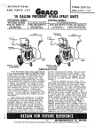
Attach mounting brackets
The S60 is shipped with mounting brackets (rack ears) and required screws for rack or cabinet installation.
The brackets are enclosed in a package with the chassis. .
Note: Force10 recommends attaching the brackets to the front of the chassis, on the PSU side. This
provides the greatest weight support for the chassis in the rack or cabinet, and is in compliance with
Bellcore Zone 4 earthquake requirements.
Follow these steps to attach the brackets to the chassis:
Step
Task
1
Take the brackets and screws out of their packaging.
2
Attach the brackets to the rear sides of the chassis, using four screws for each bracket. Attach the
bracket so that the “ear” faces to the rear and the outside of the chassis.
Power Supply
View from chassis rear
Connect to
rack/cabinet
(ear)
Screws
View of chassis front
Power Supply
4
Connect to
rack/cabinet
(ear)
Hardware Installation
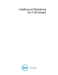
Install chassis into rack or cabinet
Ensure that there is adequate clearance surrounding the rack or within the cabinet to permit access and
airflow. If you are installing two S60 switches side-by-side, position the two chassis at least 5 inches (12.7
cm) apart to permit proper airflow. Follow the steps below to install a switch into a two-post 19-inch
equipment rack, using the already attached mounting brackets.
Step
Task
1
It is recommended that one person hold the S60 chassis in place while another attaches the brackets
to the posts.
2
Attach the bracket “ears” to the rack or cabinet posts, using two screws for each bracket. Ensure the
screws are tightened firmly.
PSU0
PSU1
Rack Mounting
"ears"
Rack/Cabinet
Post
Attach ground cable
The S60 is shipped with 2 10-32 screws for attaching a ground cable to the chassis. The cable itself is not
included. Force10 recommends a 6AWG two-hole lug, #10 hole size, .63" spacing (not included in
shipping) to properly ground the chassis. The two-hole lug must be a UL recognized, crimp-type lug.
Caution: Grounding conductors must be made of copper. Do not use aluminum conductors .
Follow these steps to connect the ground cable to the chassis:
Step
1
Task
Take the (2) 10-32 screws from the package.
S60 Quick Start Guide
5
Step
Task (Continued)
2
Cut cable to desired length. Cable length must facilitate the proper operation of fault interrupt circuits.
Force10 recommends using of the shortest cable route allowable.
3
Attach the two-hole lug to the chassis as shown, using the supplied screws.
Any un-plated mating surfaces should be brought to a shiny finish, and apply an anti-oxidant coating
to the surfaces prior to mating. Plated mating surfaces must be clean and free from contamination.
1
2
4
Attach the other end of the ground cable to a suitable ground point.
Insert Optional Modules
The S60 system has expansion slots at the front left and the rear right of the chassis, that can be used for
SFP+ devices.The following table lists the modules that can be installed into these slots. The modules are
hot-swappable; you can insert or replace modules without powering down the system
Module Description
Catalog Number
2-port 10G SFP+ optical module
S60-10GE-2S
Attention: Electrostatic discharge (ESD) damage can occur if components are mishandled. Always wear
an ESD-preventive wrist or heel ground strap when handling the S60 and its components.
To install an optional module, follow the steps below:
Step
5
6
Task
Remove the faceplate covering the module slot located at the rear left or the front right of the S60.
Hardware Installation
Step
Task
6
Remove the module from its packaging and slide the module into the slot.
7
Secure the captive screw on the side of the module.
Install the SFP and SFP+ optics
The S60 has 4 SFP optical ports in the front of the chassis in addition to the optional SFP+ optical modules.
To install SFP or SFP+ optics into an open port, follow the steps below:
Attention: Electrostatic discharge (ESD) damage can occur if components are mishandled. Always wear
an ESD-preventive wrist or heel ground strap when handling the S60 and its components.
Step
Task
1
Position the SFP or SFP+ so it is in the upright position. (The optic has a key that prevents it from
being inserted incorrectly.)
2
Insert the optic into the port until it gently snaps into place.
S60 Quick Start Guide
7
Note: For details on Force10 Networks’ supported optics, refer to http://www.force10networks.com/
products/specifications.asp
Supply power and power up the system
Supply power to the S60 after they are mounted in a rack (or on a table) and the optional modules are
installed.
Note: A US AC power cable is included in the shipping container for powering up an AC power supply. All
other power cables must be ordered separately
Attention: Electrostatic discharge (ESD) damage can occur if components are mishandled. Always wear
an ESD-preventive wrist or heel ground strap when handling the S60 and its components.
AC power
Connect the plug to each AC receptacle, making sure that the power cord is secure. As soon as the cable is
connected between the S60 and the power source, the chassis is powered-up; there is no on/off switch.
DC power
Connect the cable to the DC receptacle at the rear of the S60, making sure that the power cord is secure.
When the cable is secured, turn the power switch on.
8
Hardware Installation
Chapter 3
Getting Started
This document is intended to aid you with quick installation and set-up of a new S60 system.
•
For complete information regarding the configuration of the S60 and FTOS features, refer to the FTOS
Configuration Guide for the S60 and the FTOS Command Line Reference Guide for the S60.
The system then loads FTOS and boot messages scroll up the terminal window during this process. No
user interaction is required if the boot process proceeds without interruption.
For details on using the Command Line Interface (CLI), see the Fundamentals chapter in the FTOS
Configuration Guide for the S60.
Console access
The S60 has 2 management ports available for system access: a serial console port and a USB-B port. The
USB-B ports acts exactly as the console port.
By default, the S60 sends system messages to the serial console port. However, only one console
connection can be active at a time. When both the serial console port and the USB-B port are connected,
the system defaults to the USB-B port. The console connection is considered inactive if the USB-B port is
also connected.
You can switch between console connections by physically connecting or disconnecting the cables. A
system message is displayed on the serial console prior to switching to the USB-B console. When the
USB-B cable is detached, the system returns to the serial console default.
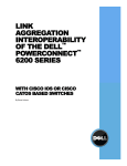
Access the RJ45 console port (RS-232)
Note: Before starting this procedure, be sure you have a terminal emulation program already installed on
your PC.
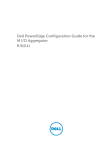
The RS-232 console port is labeled on the the S60 chassis. It is in the upper right-hand side, as you face the
rear of the chassis.
S60 Quick Start Guide
9
Figure 1 S60 serial console port connector
Console
Port
To access the console port, follow the procedures below. Refer to Table 1 for the console port pinout.
Step
Task
1
Install an RJ-45 copper cable into the console port. Use a rollover cable to connect the S60 console
port to a terminal server.
2
Connect the other end of the cable to the DTE terminal server.
3
Default terminal settings on the console are set as follows:
•
9600 baud rate
•
No parity
•
8 data bits
•
1 stop bit
•
No flow control
Accessing the RJ-45 console port with a DB-9 adapter
You can connect to the console using an RJ-45 to DB-9 adapter along with the RJ-45 rollover cable if the
DTE has a DB-9 interface. Table 1 lists the pin assignments.
Table 1 Pin Assignments Between the E300 System Console and a DTE Terminal Server
E300 System
Console Port
10
RJ-45 to RJ-45 Rollover Cable
RJ-45 to DB-9
Adapter
Terminal Server
Device
Signal
RJ-45 pinout
RJ-45 Pinout
DB-9 Pin
Signal
RTS
1
8
8
CTS
NC
2
7
6
DSR
TxD
3
6
2
RxD
GND
4
5
5
GND
GND
5
4
5
GND
RxD
6
3
3
TxD
NC
7
2
4
DTR
CTS
8
1
7
RTS
Getting Started
Access the USB-B console port
The S60 has 2 management ports available for system access: a console port and a USB-B port. The
USB-B ports acts exactly as the console port. The terminal settings are the same, and the S60 sends all
messages to the USB-B drive when it is connected.
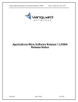
The USB-B connector port is labeled on the the S60 chassis. It is to the left of the management ports, as
you face the rear of the chassis.
Figure 2 S60 USB-B port connector
USB-B
Port
When both the console port and the USB-B port are connected, the system defaults to the USB-B port. The
console connection is considered inactive if the USB-B port is also connected.
Note: Before starting this procedure, be sure you have a terminal emulation program already installed on
your PC. You will also require appropriate drivers for the USB device in use. Contact Force10 Networks
Technical Support for assistance.
Step
Task
1
Power on the PC (XP operating system recommended)
2
Connect the USB-A end of cable (supplied) into an available USB port on the PC
3
Connect the USB-B end of cable into the USB-B console port on the S60 (
4
Power on the S60.
5
Install necessary USB device drivers (internet connection required).
Contact Force10 Networks Technical Support for assistance if necessary.
6
Open your terminal software emulation program to access the S60.
S60 Quick Start Guide
11
Step
7
Task (Continued)
Using the terminal settings shown here, set the terminal connection settings.
•
8
12
9600 baud rate, No parity, 8 data bits, 1 stop bit, No flow control
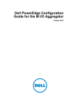
The CLI command prompt appears (shown below) when you are connected to the S60.
Getting Started
Figure 3 Completed Boot Process
######## #######
###
###
##
###
###
###
###
###
##
###### ###
##
###
###
##
###
###
###
###
###
###
###
#####
#########
########
###
### ####
###
### ###
###
#### ###
######### ###
### #### ###
###
#### ####
###
### #####
##
###
###
######
########
###
###
########
########
###
###
########
########
.*************.
.# ####
#######.
.#. ###### ###########.
.##. ## ### ####
###.
*#.
### ###
#*
*#
-## ###
#*
*#
### ##
#*
*#
#### ###
#*
*#. #### ###
###*
.#.#####
####
#### .
.###### ############ .
.#
######### .
`************'
Copyright 1999-2006 Force10 Networks, Inc.
+
+
+
+
+
+
Force10 Networks, Inc.
CPU: DB-MV64460-BP/IBM750Fx (2.3)
Version: VxWorks5.5.1
Memory Size: 1038876672 bytes.
BSP Version: 1.2/1.3.6
Creation Date : Jan 2 2007
nvDrvInit: nvDrvErase passed
-> 00:00:10: %RPM0-U:CP %RAM-6-ELECTION_ROLE: RPM0 is transitioning to Primary RPM.
00:00:11: %RPM0-P:CP %CHMGR-2-FAN_BAD: Minor alarm: some fans in fan tray 0 are down
00:00:11: %RPM0-P:CP %CHMGR-5-CARDDETECTED: Line card 1 present
DSA Card
00:00:11:
available
00:00:12:
00:00:12:
00:00:12:
00:00:13:
Init
%RPM0-P:CP POEMGR-4-POE_POWER_USAGE_ABOVE_THRESHOLD: Inline power used is exceeded 90% o
inline power
%RPM0-P:CP %CHMGR-5-CARDDETECTED: Line card 2 present
%RPM0-P:CP %TSM-6-SFM_SWITCHFAB_STATE: Switch Fabric: UP
%RPM0-P:CP %TSM-6-SFM_FULL_PARTIAL_STATE: SW_FAB_UP_1 SFM in the system
%RPM0-P:CP %IFMGR-5-OSTATE_UP: Changed interface state to up: Ma 0/0
00:01:27:
00:01:27:
00:01:28:
00:01:28:
00:01:36:
00:01:36:
%RPM0-P:CP
%RPM0-P:CP
%RPM0-P:CP
%RPM0-P:CP
%RPM0-P:CP
%RPM0-P:CP
%CHMGR-5-CHECKIN: Checkin from line
%CHMGR-5-CHECKIN: Checkin from line
%CHMGR-5-LINECARDUP: Line card 1 is
%CHMGR-5-LINECARDUP: Line card 2 is
%RAM-5-RPM_STATE: RPM0 is in Active
%CHMGR-5-CHAS_READY: Chassis ready
card 1 (type E48TB, 48 ports)
card 2 (type E48TB, 48 ports)
up
up
State.
00:01:37: %RPM0-P:CP %SEC-5-LOGIN_SUCCESS: Login successful for user
Force10>
on line console
Default Configuration
A version of FTOS is pre-loaded onto the chassis, however the system is not configured when you power
up for the first time (except for the default hostname, which is Force10). You must configure the system
using the CLI, except when using Bare Metal Auto-Configuration. Refer to the Bare Metal
Auto-Configuration chapter in the FTOS COnfiguration Guide for the S60.
S60 Quick Start Guide
13
Note: If you are using the Bare Metal Auto-Configuration feature, you do not need to proceed with the
following sections.
Configure a Host Name
The host name appears in the prompt. The default host name is force10.
•
•
Host names must start with a letter and end with a letter or digit.
Characters within the string can be letters, digits, and hyphens.
To configure a host name:
Step
1
Task
Command Syntax
Command Mode
Create a new host name.
hostname name
CONFIGURATION
Figure 4 illustrates the hostname command.
Figure 4 Configuring a Hostname
Default Hostname
Force10(conf)#hostname R1
R1(conf)#
New Hostname
Access the System Remotely
You can configure the system to access it remotely by Telnet. The method for configuring the C-Series and
E-Series for Telnet access is different from S-Series.
•
•
The C-Series and E-Series have a dedicated management port and a management routing table that is
separate from the IP routing table.
The S-Series does not have a dedicated management port, but is managed from any port. It does not
have a separate management routing table.
Access the C-Series and E-Series and the S60 Remotely
Configuring the system for Telnet is a three-step process:
14
Getting Started
1. Configure an IP address for the management port. See Configure the Management Port IP Address.
2. Configure a management route with a default gateway. See Configure a Management Route.
3. Configure a username and password. See Configure a Username and Password.
Configure the Management Port IP Address
Assign IP addresses to the management ports in order to access the system remotely.
To configure the management port IP address:
Step
1
2
Task
Command Syntax
Command Mode
Enter INTERFACE mode for the
Management port.
interface ManagementEthernet slot/port
CONFIGURATION
Assign an IP address to the
interface.
ip address ip-address/mask
•
•
•
•
3
Enable the interface.
slot range: 0 to 1
port range: 0
INTERFACE
ip-address: an address in dotted-decimal
format (A.B.C.D).
mask: a subnet mask in /prefix-length
format (/xx).
no shutdown
INTERFACE
Configure a Management Route
Define a path from the system to the network from which you are accessing the system remotely.
Management routes are separate from IP routes and are only used to manage the system through the
management port.
To configure a management route:
Step
1
Task
Command Syntax
Command Mode
Configure a management route
to the network from which you
are accessing the system.
management route ip-address/mask gateway
CONFIGURATION
•
•
•
ip-address: the network address in
dotted-decimal format (A.B.C.D).
mask: a subnet mask in /prefix-length
format (/xx).
gateway: the next hop for network traffic
originating from the management port.
Configure a Username and Password
Configure a system username and password to access the system remotely.
S60 Quick Start Guide
15
To configure a username and password:
Step
1
Task
Command Syntax
Command Mode
Configure a username and
password to access the
system remotely.
username username password [encryption-type]
password
encryption-type specifies how you are inputting
CONFIGURATION
the password, is 0 by default, and is not required.
•
•
0 is for inputting the password in clear text.
7 is for inputting a password that is already
encrypted using a Type 7 hash. Obtaining the
encrypted password from the configuration of
another Force10 system.
Access the S-Series Remotely ( on a non-management port)
The S-Series does not have a dedicated management port nor a separate management routing table.
Configure any port on the S-Series to be the port through which you manage the system and configure an
IP route to that gateway.
Note: The S60 system uses management ports and can be configured similar to the C-Series and
E-Series systems. Refer to Access the C-Series and E-Series and the S60 Remotely.
Configuring the system for Telnet access is a three-step process:
1. Configure an IP address for the port through which you will manage the system using the command ip
address from INTERFACE mode, as shown in Figure 5.
2. Configure a IP route with a default gateway using the command ip route from CONFIGURATION
mode, as shown in Figure 5.
3. Configure a username and password using the command username from CONFIGURATION mode,
as shown in Figure 5.
16
Getting Started
Figure 5 Configuring the S-Series for Remote Access
R5(conf)#int gig 0/48
R5(conf-if-gi-0/48)#ip address 10.11.131.240
R5(conf-if-gi-0/48)#show config
!
interface GigabitEthernet 0/48
ip address 10.11.131.240/24
no shutdown
R5(conf-if-gi-0/48)#exit
R5(conf)#ip route 10.11.32.0/23 10.11.131.254
R5(conf)#username admin pass force10
Configure the Enable Password
Access the EXEC Privilege mode using the enable command. The EXEC Privilege mode is unrestricted
by default. Configure a password as a basic security measure. There are two types of enable passwords:
•
enable password
stores the password in the running/startup configuration using a DES encryption
method.
•
enable secret is
stored in the running/startup configuration in using a stronger, MD5 encryption
method.
Force10 recommends using the enable secret password.
To configure an enable password:
Task
Command Syntax
Command Mode
Create a password to
access EXEC Privilege
mode.
enable [password | secret] [level level] [encryption-type]
CONFIGURATION
password
level is the privilege level, is 15 by default, and is not required.
encryption-type specifies how you are inputting the password,
is 0 by default, and is not required.
•
•
•
0 is for inputting the password in clear text.
7 is for inputting a password that is already encrypted using
a DES hash. Obtain the encrypted password from the
configuration file of another Force10 system.
5 is for inputting a password that is already encrypted using
an MD5 hash. Obtain the encrypted password from the
configuration file of another Force10 system.
Configuration File Management
Files can be stored on and accessed from various storage media. Rename, delete, and copy files on the
system from the EXEC Privilege mode.
S60 Quick Start Guide
17
The E-Series EtherScale platform architecture uses MMC cards for both the internal and external Flash
memory. MMC cards support a maximum of 100 files. The E-Series TeraScale and ExaScale platforms
architecture use Compact Flash for the internal and external Flash memory. It has a space limitation but
does not limit the number of files it can contain.
Note: Using flash memory cards in the system that have not been approved by Force10 can cause
unexpected system behavior, including a reboot.
Copy Files to and from the System
The command syntax for copying files is similar to UNIX. The copy command uses the format copy
source-file-url destination-file-url.
Note: See the FTOS Command Reference for a detailed description of the copy command.
•
•
To copy a local file to a remote system, combine the file-origin syntax for a local file location with the
file-destination syntax for a remote file location shown in Table 2.
To copy a remote file to Force10 system, combine the file-origin syntax for a remote file location with
the file-destination syntax for a local file location shown in Table 2.
Table 2 Forming a copy Command
source-file-url Syntax
destination-file-url Syntax
primary RPM
copy flash://filename
flash://filename
standby RPM
copy rpm{0|1}flash://filename
rpm{0|1}flash://filename
primary RPM
copy rpm{0|1}slot0://filename
rpm{0|1}slot0://filename
standby RPM
copy rpm{0|1}slot0://filename
rpm{0|1}slot0://filename
USB drive on RPM0
copy rpm0usbflash://filepath
rpm0usbflash://filename
External USB drive
copy usbflash://filepath
usbflash://filename
copy ftp://username:password@{hostip
ftp://username:password@{hostip |
hostname}/filepath/filename
Local File Location
Internal flash:
External flash:
USB Drive (
Remote File Location
FTP server
| hostname}/filepath/filename
TFTP server
copy tftp://{hostip | hostname}/filepath/
filename
SCP server
copy scp://{hostip | hostname}/filepath/ scp://{hostip | hostname}/filepath/filename
filename
18
tftp://{hostip | hostname}/filepath/filename
Getting Started
Important Points to Remember
•
•
•
•
•
You may not copy a file from one remote system to another.
You may not copy a file from one location to the same location.
The internal flash memories on the RPMs are synchronized whenever there is a change, but only if
both RPMs are running the same version of FTOS.
When copying to a server, a hostname can only be used if a DNS server is configured.
The usbflash and rpm0usbflash commands are supported on E-Series ExaScale platform only.
Refer to the FTOS Release Notes for a list of approved USB vendors.
Figure 6 shows an example of using the copy command to save a file to an FTP server.
Figure 6 Saving a file to a Remote System
Local Location
Remote Location
Force10#copy flash://FTOS-SB-8.3.3.1.bin ftp://myusername:[email protected]//FTOS/FTOS-SB-8.3.3.1
!!!!!!!!!!!!!!!!!!!!!!!!!!!!!!!!!!!!!!!!!!!!!!!!!!!!!!!!!!!!!!!!!!!!!!!!!!!!!
27952672 bytes successfully copied
Figure 7 shows an example of using the copy command to import a file to the Force10 system from an FTP
server.
Figure 7 Saving a file to a Remote System
Remote Location
Local Location
Force10#$//copy ftp://myusername:[email protected]//FTOS/FTOS-SB-8.3.3.1.bin flash://
Destination file name [FTOS-EF-8.3.3.1.bin.bin]:
!!!!!!!!!!!!!!!!!!!!!!!!!!!!!!!!!!!!!!!!!!!!!!!!!!!!!!!!!!!!!!!!
26292881 bytes successfully copied
Save the Running-configuration
The running-configuration contains the current system configuration. Force10 recommends that you copy
your running-configuration to the startup-configuration. The system uses the startup-configuration during
boot-up to configure the system. The startup-configuration is stored in the internal flash on the primary
RPM by default, but it can be saved onto an external flash (on an RPM) or a remote server.
To save the running-configuration:
Note: The commands in this section follow the same format as those in Copy Files to and from the
System on page 18 but use the filenames startup-configuration and running-configuration. These
commands assume that current directory is the internal flash, which is the system default.
S60 Quick Start Guide
19
Task
Command Syntax
Command Mode
Save the running-configuration to:
the startup-configuration on the
internal flash of the primary
RPM
copy running-config startup-config
the internal flash on an RPM
copy running-config rpm{0|1}flash://filename
Note: The internal flash memories on the RPMs are synchronized whenever there
is a change, but only if the RPMs are running the same version of FTOS.
the external flash of an RPM
copy running-config rpm{0|1}slot0://filename
an FTP server
copy running-config ftp://
username:password@{hostip | hostname}/
filepath/filename
a TFTP server
copy running-config tftp://{hostip | hostname}/
filepath/filename
an SCP server
copy running-config scp://{hostip | hostname}/
filepath/filename
EXEC Privilege
Note: When copying to a server, a hostname can only be used if a DNS server is configured.
Save the running-configuration to the
startup-configuration on the internal
flash of the primary RPM. Then copy
the new startup-config file to the
external flash of the primary RPM.
copy running-config startup-config duplicate
EXEC Privilege
View Files
File information and content can only be viewed on local file systems.
To view a list of files on the internal or external Flash:
Step
1
Task
Command Syntax
Command Mode
the internal flash of an RPM
dir flash:
EXEC Privilege
the external flash of an RPM
dir slot:
View a list of files on:
The output of the command dir also shows the read/write privileges, size (in bytes), and date of
modification for each file, as shown in Figure 8.
20
Getting Started
Figure 8 Viewing a List of Files in the Internal Flash
Force10#dir
Directory of flash:
1 drw2 drwx
3 drw4 drw5 drw6 drw7 d--8 -rw9 -rw10 -rw11 drw12 -rw13 -rw14 -rw15 -rw--More--
32768
512
8192
8192
8192
8192
8192
33059550
27674906
27674906
8192
7276
7341
27674906
27674906
Jan
Jul
Mar
Mar
Mar
Mar
Mar
Jul
Jul
Jul
Jan
Jul
Jul
Jul
Jul
01
23
30
30
30
30
30
11
06
06
01
20
20
06
06
1980
2007
1919
1919
1919
1919
1919
2007
2007
2007
1980
2007
2007
2007
2007
00:00:00
00:38:44
10:31:04
10:31:04
10:31:04
10:31:04
10:31:04
17:49:46
00:20:24
19:54:52
00:18:28
01:52:40
15:34:46
19:52:22
02:23:22
.
..
TRACE_LOG_DIR
CRASH_LOG_DIR
NVTRACE_LOG_DIR
CORE_DUMP_DIR
ADMIN_DIR
FTOS-EF-7.4.2.0.bin
FTOS-EF-4.7.4.302.bin
boot-image-FILE
diag
startup-config.bak
startup-config
boot-image
boot-flash
To view the contents of a file:
Step
1
Task
Command Syntax
Command Mode
View the:
contents of a file in the internal
flash of an RPM
show file rpm{0|1}flash://filename
contents of a file in the external
flash of an RPM
show file rpm{0|1}slot0://filename
running-configuration
show running-config
startup-configuration
show startup-config
EXEC Privilege
View Configuration Files
Configuration files have three commented lines at the beginning of the file, as shown in Figure 9, to help
you track the last time any user made a change to the file, which user made the changes, and when the file
was last saved to the startup-configuration.
In the running-configuration file, if there is a difference between the timestamp on the “Last configuration
change,” and “Startup-config last updated,” then you have made changes that have not been saved and will
not be preserved upon a system reboot.
S60 Quick Start Guide
21
Figure 9 Tracking Changes with Configuration Comments
Force10#show running-config
Current Configuration ...
! Version 8.2.1.0
! Last configuration change at Thu Apr 3 23:06:28 2008 by admin
! Startup-config last updated at Thu Apr 3 23:06:55 2008 by admin
!
boot system rpm0 primary flash://FTOS-EF-8.2.1.0.bin
boot system rpm0 secondary flash://FTOS-EF-7.8.1.0.bin
boot system rpm0 default flash://FTOS-EF-7.7.1.1.bin
boot system rpm1 primary flash://FTOS-EF-7.8.1.0.bin
boot system gateway 10.10.10.100
--More--
File System Management
The Force10 system can use the internal Flash, external Flash, or remote devices to store files. It stores
files on the internal Flash by default but can be configured to store files elsewhere.
To view file system information:
Task
Command Syntax
Command Mode
View information about each file system.
show file-systems
EXEC Privilege
The output of the command show file-systems (Figure 10) shows the total capacity, amount of free
memory, file structure, media type, read/write privileges for each storage device in use.
Figure 10 show file-systems Command Example
Force10#show file-systems
Size(b)
Free(b)
Feature
Type
Flags
520962048
213778432
dosFs2.0 USERFLASH
127772672
21936128
dosFs2.0 USERFLASH
network
network
network
Prefixes
rw flash:
rw slot0:
rw ftp:
rw tftp:
rw scp:
You can change the default file system so that file management commands apply to a particular device or
memory.
To change the default storage location:
Task
Command Syntax
Command Mode
Change the default directory.
cd directory
EXEC Privilege
In Figure 11, the default storage location is changed to the external Flash of the primary RPM. File
management commands then apply to the external Flash rather than the internal Flash.
22
Getting Started
Figure 11 Alternative Storage Location
Force10#cd slot0:
Force10#copy running-config test
Force10#copy run test
!
7419 bytes successfully copied
Force10#dir
Directory of slot0:
1
2
3
4
5
6
7
8
9
drwdrwx
----rw----------------
32768
512
0
7419
0
0
0
0
0
Jan
Jul
Jan
Jul
Jan
Jan
Jan
Jan
Jan
01
23
01
23
01
01
01
01
01
1980
2007
1970
2007
1970
1970
1970
1970
1970
No File System Specified
00:00:00
00:38:44
00:00:00
20:44:40
00:00:00
00:00:00
00:00:00
00:00:00
00:00:00
.
..
DCIM
test
BT
200702~1VSN
G
F
F
File Saved to External Flash
slot0: 127772672 bytes total (21927936 bytes free)
View command history
The command-history trace feature captures all commands entered by all users of the system with a time
stamp and writes these messages to a dedicated trace log buffer. The system generates a trace message for
each executed command. No password information is saved to the file.
To view the command-history trace, use the show command-history command, as shown in Figure 487.
Figure 12 Command Example show command-history
Force10#show command-history
[12/5 10:57:8]: CMD-(CLI):service password-encryption
[12/5 10:57:12]: CMD-(CLI):hostname Force10
[12/5 10:57:12]: CMD-(CLI):ip telnet server enable
[12/5 10:57:12]: CMD-(CLI):line console 0
[12/5 10:57:12]: CMD-(CLI):line vty 0 9
[12/5 10:57:13]: CMD-(CLI):boot system rpm0 primary flash://FTOS-CB-1.1.1.2E2.bin
Upgrading and Downgrading FTOS
Note: To upgrade or downgrade FTOS, see the release notes for the version you want to load on the
system.
S60 Quick Start Guide
23
24
Getting Started