1
Force10 Node Manager Guide
Version 1.5.0
July 2007
Copyright 2007 Force10 Networks
All rights reserved. Printed in the USA. July 2007.
Force10 Networks® reserves the right to change, modify, revise this publication without notice.
Trademarks
Force10 Networks® and E-Series® are registered trademarks of Force10 Networks, Inc. Force10, the Force10 logo, E1200, E600, E600i,
E300, EtherScale, TeraScale, and FTOS are trademarks of Force10 Networks, Inc. All other brand and product names are registered
trademarks or trademarks of their respective holders.
Statement of Conditions
In the interest of improving internal design, operational function, and/or reliability, Force10 Networks reserves the right to make changes to
products described in this document without notice. Force10 Networks does not assume any liability that may occur due to the use or
application of the product(s) described herein.
USA Federal Communications Commission (FCC) Statement
This equipment has been tested and found to comply with the limits for a Class A digital device, pursuant to Part 15 of the FCC rules. These
limits are designated to provide reasonable protection against harmful interference when the equipment is operated in a commercial
environment. This equipment generates, uses, and can radiate radio frequency energy. If it is not installed and used in accordance to the
instructions, it may cause harmful interference to radio communications. Operation of this equipment in a residential area is likely to cause
harmful interference, in which case users will be required to take whatever measures necessary to correct the interference at their own
expense.
Properly shielded and grounded cables and connectors must be used in order to meet FCC emission limits. Force10 Networks is not
responsible for any radio or television interference caused by using other than recommended cables and connectors or by unauthorized
changes or modifications in the equipment. Unauthorized changes or modification could void the user’s authority to operate the equipment.
This device complies with Part 15 of the FCC Rules. Operation is subject to the following two conditions: (1) this device may not cause
harmful interference, and (2) this device must accept any interference received, including interference that may cause undesired operation.
Canadian Department of Communication Statement
The digital apparatus does not exceed the Class A limits for radio noise emissions from digital apparatus set out in the Radio Interference
Regulations of the Canadian Department of Communications.
Attention: Le present appareil numerique n’ emet pas de perturbations radioelectriques depassant les normes applicables aux appareils
numeriques de la Class A prescrites dans le Reglement sur les interferences radioelectriques etabli par le ministere des Communications du
Canada.
European Union EMC Directive Conformance Statement
This product is in conformity with the protection requirements of EU Council Directive 89/336/EEC on the approximation of the laws of the
Member States relating to electromagnetic compatibility. Force 10 Networks can not accept responsibility for any failure to satisfy the
protection requirements resulting from a non-recommended modification of this product, including the fitting of non-Force10 option cards.
This product has been tested and found to comply with the limits for Class A Information Technology Equipment according to CISPR 22/
European Standard EN 55022. The limits for Class A equipment were derived for commercial and industrial environments to provide
reasonable protection against interference with licensed communication equipment.
Warning: This device is a Class A product. In a domestic environment, this device can cause radio interference, in
which case, the user may be required to take appropriate measures.
VCCI Compliance for Class A Equipment (Japan)
This is Class A product based on the standard of the Voluntary Control Council For Interference by Information Technology Equipment
(VCCI). If this equipment is used in a domestic environment, radio disturbance may arise. When such trouble occurs, the user may be
required to take corrective actions.\
Danger: AC Power cords are for use with Force10 Networks equipment only, do not use Force10 Networks AC Power
cords with any unauthorized hardware.
New Features
This preface describes major changes in Node Manager version 1.5 and in this edition of the Force10
Node Manager Guide.
Note that the changes in Node Manager 1.5 appear also in FTMS 1.5, because FTMS includes Node
Manager.
New Features
•
•
•
Username tracking and syslog viewable from FTMS GUI – change control/auditing
Port-based permission assignment: access control; restrict Telnet and SSH access
Support added for the following Force10 switches:
C300 and its line cards
S2410CP
S2410P
S50N (and S50N-DC — Node Manager does not distinguish between them.)
For details, see Supported Devices on page 113.
Major Changes to this Document
This edition contains the following major revisions:
•
•
An added C-Series chapter (Managing the C-Series on page 35)
Appendix A updated with information on supported E-Series and S-Series devices (see Appendix A,
Supported Devices).
Force10 Node Manager Guide, version 1.5.0
3
4
New Features
Contents
New Features . . . . . . . . . . . . . . . . . . . . . . . . . . . . . . . . . . . . . . . . . . . . . . . . . . . . . . . . . . . . . . . 3
New Features . . . . . . . . . . . . . . . . . . . . . . . . . . . . . . . . . . . . . . . . . . . . . . . . . . . . . . . . . . . . . . . . . . . 3
Major Changes to this Document . . . . . . . . . . . . . . . . . . . . . . . . . . . . . . . . . . . . . . . . . . . . . . . . . . . . 3
Contents . . . . . . . . . . . . . . . . . . . . . . . . . . . . . . . . . . . . . . . . . . . . . . . . . . . . . . . . . . . . . . . . . . . 5
Chapter 1
Introduction . . . . . . . . . . . . . . . . . . . . . . . . . . . . . . . . . . . . . . . . . . . . . . . . . . . . . . . . . . . . . . . 15
Overview . . . . . . . . . . . . . . . . . . . . . . . . . . . . . . . . . . . . . . . . . . . . . . . . . . . . . . . . . . . . . . . . . . . . . . 15
Objectives . . . . . . . . . . . . . . . . . . . . . . . . . . . . . . . . . . . . . . . . . . . . . . . . . . . . . . . . . . . . . . . . . . . . . 15
Audience . . . . . . . . . . . . . . . . . . . . . . . . . . . . . . . . . . . . . . . . . . . . . . . . . . . . . . . . . . . . . . . . . . . . . . 16
Conventions . . . . . . . . . . . . . . . . . . . . . . . . . . . . . . . . . . . . . . . . . . . . . . . . . . . . . . . . . . . . . . . . . . . . 16
Related Publications . . . . . . . . . . . . . . . . . . . . . . . . . . . . . . . . . . . . . . . . . . . . . . . . . . . . . . . . . . . . . 16
Chapter 2
Installation . . . . . . . . . . . . . . . . . . . . . . . . . . . . . . . . . . . . . . . . . . . . . . . . . . . . . . . . . . . . . . . . 17
Minimum System Requirements . . . . . . . . . . . . . . . . . . . . . . . . . . . . . . . . . . . . . . . . . . . . . . . . . . . . 17
Solaris . . . . . . . . . . . . . . . . . . . . . . . . . . . . . . . . . . . . . . . . . . . . . . . . . . . . . . . . . . . . . . . . . . . . . 17
Linux . . . . . . . . . . . . . . . . . . . . . . . . . . . . . . . . . . . . . . . . . . . . . . . . . . . . . . . . . . . . . . . . . . . . . . 17
Node Manager Installation . . . . . . . . . . . . . . . . . . . . . . . . . . . . . . . . . . . . . . . . . . . . . . . . . . . . . . . . . 18
C-Series and E-Series Setup . . . . . . . . . . . . . . . . . . . . . . . . . . . . . . . . . . . . . . . . . . . . . . . . . . . . . . 25
Configuring SNMP . . . . . . . . . . . . . . . . . . . . . . . . . . . . . . . . . . . . . . . . . . . . . . . . . . . . . . . . . . . 25
Defining a Virtual IP Address . . . . . . . . . . . . . . . . . . . . . . . . . . . . . . . . . . . . . . . . . . . . . . . . . . . 25
S-Series Setup . . . . . . . . . . . . . . . . . . . . . . . . . . . . . . . . . . . . . . . . . . . . . . . . . . . . . . . . . . . . . . . . . 26
Configuring SNMP . . . . . . . . . . . . . . . . . . . . . . . . . . . . . . . . . . . . . . . . . . . . . . . . . . . . . . . . . . . 26
Defining the S-Series Management IP Address . . . . . . . . . . . . . . . . . . . . . . . . . . . . . . . . . . . . . 26
Chapter 3
Using Node Manager . . . . . . . . . . . . . . . . . . . . . . . . . . . . . . . . . . . . . . . . . . . . . . . . . . . . . . . 27
Launching Node Manager . . . . . . . . . . . . . . . . . . . . . . . . . . . . . . . . . . . . . . . . . . . . . . . . . . . . . . . . . 27
Using the Menus . . . . . . . . . . . . . . . . . . . . . . . . . . . . . . . . . . . . . . . . . . . . . . . . . . . . . . . . . . . . . . . . 29
Using Keyboard Commands . . . . . . . . . . . . . . . . . . . . . . . . . . . . . . . . . . . . . . . . . . . . . . . . . . . . . . . 30
Selecting Objects . . . . . . . . . . . . . . . . . . . . . . . . . . . . . . . . . . . . . . . . . . . . . . . . . . . . . . . . . . . . . . . . 30
Labels, Status Colors, and Indicator LEDs . . . . . . . . . . . . . . . . . . . . . . . . . . . . . . . . . . . . . . . . . . . . 31
Labels . . . . . . . . . . . . . . . . . . . . . . . . . . . . . . . . . . . . . . . . . . . . . . . . . . . . . . . . . . . . . . . . . . . . . 31
Status Colors and Indicator LEDs . . . . . . . . . . . . . . . . . . . . . . . . . . . . . . . . . . . . . . . . . . . . . . . . 31
Force10 Node Manager Guide, version 1.5.0
5
The System Message Bar . . . . . . . . . . . . . . . . . . . . . . . . . . . . . . . . . . . . . . . . . . . . . . . . . . . . . . . . . 32
Copying and Pasting Text . . . . . . . . . . . . . . . . . . . . . . . . . . . . . . . . . . . . . . . . . . . . . . . . . . . . . . . . . 32
Finding Help . . . . . . . . . . . . . . . . . . . . . . . . . . . . . . . . . . . . . . . . . . . . . . . . . . . . . . . . . . . . . . . . . . . 33
Configuring Refresh Rate and SNMP Properties (Optional) . . . . . . . . . . . . . . . . . . . . . . . . . . . . . . . 33
Chapter 4
Managing the C-Series . . . . . . . . . . . . . . . . . . . . . . . . . . . . . . . . . . . . . . . . . . . . . . . . . . . . . . 35
Navigating the C300 Chassis . . . . . . . . . . . . . . . . . . . . . . . . . . . . . . . . . . . . . . . . . . . . . . . . . . . . . . 36
Chapter 5
Managing the E-Series . . . . . . . . . . . . . . . . . . . . . . . . . . . . . . . . . . . . . . . . . . . . . . . . . . . . . . 39
Navigating the E-Series Chassis . . . . . . . . . . . . . . . . . . . . . . . . . . . . . . . . . . . . . . . . . . . . . . . . . . . . 39
The E1200 Chassis View . . . . . . . . . . . . . . . . . . . . . . . . . . . . . . . . . . . . . . . . . . . . . . . . . . . . . . 40
The E600 Chassis View . . . . . . . . . . . . . . . . . . . . . . . . . . . . . . . . . . . . . . . . . . . . . . . . . . . . . . . 41
The E300 Chassis View . . . . . . . . . . . . . . . . . . . . . . . . . . . . . . . . . . . . . . . . . . . . . . . . . . . . . . . 42
Displaying E-Series Chassis Information . . . . . . . . . . . . . . . . . . . . . . . . . . . . . . . . . . . . . . . . . . . . . 42
Managing Performance Templates . . . . . . . . . . . . . . . . . . . . . . . . . . . . . . . . . . . . . . . . . . . . . . . 45
Managing E-Series RPMs . . . . . . . . . . . . . . . . . . . . . . . . . . . . . . . . . . . . . . . . . . . . . . . . . . . . . . . . . 46
Viewing RPM Information . . . . . . . . . . . . . . . . . . . . . . . . . . . . . . . . . . . . . . . . . . . . . . . . . . . . . . 46
Configuring RPMs . . . . . . . . . . . . . . . . . . . . . . . . . . . . . . . . . . . . . . . . . . . . . . . . . . . . . . . . . . . . 52
Managing Line Cards . . . . . . . . . . . . . . . . . . . . . . . . . . . . . . . . . . . . . . . . . . . . . . . . . . . . . . . . . . . . 55
Displaying Line Card Information . . . . . . . . . . . . . . . . . . . . . . . . . . . . . . . . . . . . . . . . . . . . . . . . 56
Adding Logical Line Cards . . . . . . . . . . . . . . . . . . . . . . . . . . . . . . . . . . . . . . . . . . . . . . . . . . . . . 59
Deleting Logical Line Cards . . . . . . . . . . . . . . . . . . . . . . . . . . . . . . . . . . . . . . . . . . . . . . . . . . . . 60
Managing E-Series Interfaces . . . . . . . . . . . . . . . . . . . . . . . . . . . . . . . . . . . . . . . . . . . . . . . . . . . . . . 61
Viewing Interface Information . . . . . . . . . . . . . . . . . . . . . . . . . . . . . . . . . . . . . . . . . . . . . . . . . . . 61
Configuring Interfaces . . . . . . . . . . . . . . . . . . . . . . . . . . . . . . . . . . . . . . . . . . . . . . . . . . . . . . . . . 63
Managing OSPF Areas . . . . . . . . . . . . . . . . . . . . . . . . . . . . . . . . . . . . . . . . . . . . . . . . . . . . . . . . . . . 66
Adding a Network to an OSPF Area . . . . . . . . . . . . . . . . . . . . . . . . . . . . . . . . . . . . . . . . . . . . . . 66
Removing a Network from an OSPF Area . . . . . . . . . . . . . . . . . . . . . . . . . . . . . . . . . . . . . . . . . 67
Managing E-Series Port Channels . . . . . . . . . . . . . . . . . . . . . . . . . . . . . . . . . . . . . . . . . . . . . . . . . . 67
Viewing E-Series Port Channel Information . . . . . . . . . . . . . . . . . . . . . . . . . . . . . . . . . . . . . . . . 68
Adding E-Series Port Channels . . . . . . . . . . . . . . . . . . . . . . . . . . . . . . . . . . . . . . . . . . . . . . . . . 72
Deleting E-Series Port Channels . . . . . . . . . . . . . . . . . . . . . . . . . . . . . . . . . . . . . . . . . . . . . . . . 73
Configuring E-Series Port Channels . . . . . . . . . . . . . . . . . . . . . . . . . . . . . . . . . . . . . . . . . . . . . . 74
Viewing SFM Information . . . . . . . . . . . . . . . . . . . . . . . . . . . . . . . . . . . . . . . . . . . . . . . . . . . . . . . . . . 77
Checking SFM Status Visually . . . . . . . . . . . . . . . . . . . . . . . . . . . . . . . . . . . . . . . . . . . . . . . . . . 78
Displaying Detailed SFM Performance Information . . . . . . . . . . . . . . . . . . . . . . . . . . . . . . . . . . 78
Viewing Power Supply Information . . . . . . . . . . . . . . . . . . . . . . . . . . . . . . . . . . . . . . . . . . . . . . . . . . 79
Checking E1200 and E600 PEMs Visually . . . . . . . . . . . . . . . . . . . . . . . . . . . . . . . . . . . . . . . . . 79
Displaying More E1200 and E600 Power Supply Information . . . . . . . . . . . . . . . . . . . . . . . . . . 80
Checking the Status of E300 AC Power Supplies . . . . . . . . . . . . . . . . . . . . . . . . . . . . . . . . . . . . 80
Viewing Fan Tray Information . . . . . . . . . . . . . . . . . . . . . . . . . . . . . . . . . . . . . . . . . . . . . . . . . . . . . . 81
Checking Fan Tray Status on the E1200 and E600 . . . . . . . . . . . . . . . . . . . . . . . . . . . . . . . . . . 81
6
Checking Fan Tray Status on the E300 . . . . . . . . . . . . . . . . . . . . . . . . . . . . . . . . . . . . . . . . . . . . 81
Using Bulk Configuration . . . . . . . . . . . . . . . . . . . . . . . . . . . . . . . . . . . . . . . . . . . . . . . . . . . . . . . . . . 82
Chapter 6
Managing the S-Series . . . . . . . . . . . . . . . . . . . . . . . . . . . . . . . . . . . . . . . . . . . . . . . . . . . . . . 85
Navigating the S-Series Switch . . . . . . . . . . . . . . . . . . . . . . . . . . . . . . . . . . . . . . . . . . . . . . . . . . . . . 85
Displaying S-Series Chassis Information . . . . . . . . . . . . . . . . . . . . . . . . . . . . . . . . . . . . . . . . . . . . . 86
Using the Show Submenu for the S-Series Chassis . . . . . . . . . . . . . . . . . . . . . . . . . . . . . . . . . . 87
Managing S-Series Switches in a Stack . . . . . . . . . . . . . . . . . . . . . . . . . . . . . . . . . . . . . . . . . . . . . . 90
Adding S-Series Switches to a Stack . . . . . . . . . . . . . . . . . . . . . . . . . . . . . . . . . . . . . . . . . . . . . 90
Deleting Member Switches from an S50 Stack . . . . . . . . . . . . . . . . . . . . . . . . . . . . . . . . . . . . . . 91
Renumbering a Switch Member in an S50 Stack . . . . . . . . . . . . . . . . . . . . . . . . . . . . . . . . . . . . 92
Setting Priority on a Switch Member in an S50 Stack . . . . . . . . . . . . . . . . . . . . . . . . . . . . . . . . . 92
Managing S-Series Interfaces . . . . . . . . . . . . . . . . . . . . . . . . . . . . . . . . . . . . . . . . . . . . . . . . . . . . . . 93
Displaying S-Series Interface Information . . . . . . . . . . . . . . . . . . . . . . . . . . . . . . . . . . . . . . . . . . 93
Analyzing S-Series Interface Performance . . . . . . . . . . . . . . . . . . . . . . . . . . . . . . . . . . . . . . . . . 96
Configuring S-Series Interfaces . . . . . . . . . . . . . . . . . . . . . . . . . . . . . . . . . . . . . . . . . . . . . . . . . . . . . 97
Configuring S-Series Switch Interfaces . . . . . . . . . . . . . . . . . . . . . . . . . . . . . . . . . . . . . . . . . . . . 97
Enabling and Shutting Down S-Series Ports . . . . . . . . . . . . . . . . . . . . . . . . . . . . . . . . . . . . . . . . 98
Telneting to an S-Series Switch Interface . . . . . . . . . . . . . . . . . . . . . . . . . . . . . . . . . . . . . . . . . . 98
Managing S-Series Port Channels . . . . . . . . . . . . . . . . . . . . . . . . . . . . . . . . . . . . . . . . . . . . . . . . . . 99
Viewing S-Series Port Channel Information . . . . . . . . . . . . . . . . . . . . . . . . . . . . . . . . . . . . . . . 100
Adding S-Series Port Channels . . . . . . . . . . . . . . . . . . . . . . . . . . . . . . . . . . . . . . . . . . . . . . . . 104
Deleting S-Series Port Channels . . . . . . . . . . . . . . . . . . . . . . . . . . . . . . . . . . . . . . . . . . . . . . . 106
Configuring S-Series Port Channels . . . . . . . . . . . . . . . . . . . . . . . . . . . . . . . . . . . . . . . . . . . . . 107
Starting S-Series Port Channels . . . . . . . . . . . . . . . . . . . . . . . . . . . . . . . . . . . . . . . . . . . . . . . . 107
Shutting Down S-Series Port Channels . . . . . . . . . . . . . . . . . . . . . . . . . . . . . . . . . . . . . . . . . . 108
Telneting to an S50 Port Channel . . . . . . . . . . . . . . . . . . . . . . . . . . . . . . . . . . . . . . . . . . . . . . . 108
Using S-Series Bulk Configuration . . . . . . . . . . . . . . . . . . . . . . . . . . . . . . . . . . . . . . . . . . . . . . . . . .110
Appendix A
Supported Devices . . . . . . . . . . . . . . . . . . . . . . . . . . . . . . . . . . . . . . . . . . . . . . . . . . . . . . . . 113
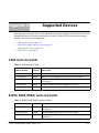
C300 and Line Cards . . . . . . . . . . . . . . . . . . . . . . . . . . . . . . . . . . . . . . . . . . . . . . . . . . . . . . . . . . . . .113
E1200, E600, E600i, and Line Cards . . . . . . . . . . . . . . . . . . . . . . . . . . . . . . . . . . . . . . . . . . . . . . . .113
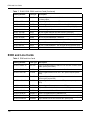
E300 and Line Cards . . . . . . . . . . . . . . . . . . . . . . . . . . . . . . . . . . . . . . . . . . . . . . . . . . . . . . . . . . . .114
S-Series Devices . . . . . . . . . . . . . . . . . . . . . . . . . . . . . . . . . . . . . . . . . . . . . . . . . . . . . . . . . . . . . . . .115
Appendix B
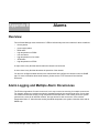
Alarms. . . . . . . . . . . . . . . . . . . . . . . . . . . . . . . . . . . . . . . . . . . . . . . . . . . . . . . . . . . . . . . . . . . 117
Overview . . . . . . . . . . . . . . . . . . . . . . . . . . . . . . . . . . . . . . . . . . . . . . . . . . . . . . . . . . . . . . . . . . . . . .117
Alarm Logging and Multiple Alarm Occurrences . . . . . . . . . . . . . . . . . . . . . . . . . . . . . . . . . . . . . . . .117
Index . . . . . . . . . . . . . . . . . . . . . . . . . . . . . . . . . . . . . . . . . . . . . . . . . . . . . . . . . . . . . . . . . . . . 119
Force10 Node Manager Guide, version 1.5.0
7
8
List of Figures
Figure 1
Introduction Screen of Installation Wizard . . . . . . . . . . . . . . . . . . . . . . . . . . . . 19
Figure 2
Choose Install Folder Screen of Installation Wizard . . . . . . . . . . . . . . . . . . . . . 20
Figure 3
Choose Shortcut Folder Screen of Installation Wizard . . . . . . . . . . . . . . . . . . . 21
Figure 4
Choose Install Set (for Solaris) Screen of Installation Wizard. . . . . . . . . . . . . . 23
Figure 5
Choose HP OpenView Home Directory Screen of Installation Wizard . . . . . . 24
Figure 6
Node Manager Launch Screen . . . . . . . . . . . . . . . . . . . . . . . . . . . . . . . . . . . . 27
Figure 7
E300 Chassis View . . . . . . . . . . . . . . . . . . . . . . . . . . . . . . . . . . . . . . . . . . . . . 28
Figure 8
Login to CLI Screen . . . . . . . . . . . . . . . . . . . . . . . . . . . . . . . . . . . . . . . . . . . . . 29
Figure 9
Node Manager Main Menu . . . . . . . . . . . . . . . . . . . . . . . . . . . . . . . . . . . . . . . . 30
Figure 10
Selection Example . . . . . . . . . . . . . . . . . . . . . . . . . . . . . . . . . . . . . . . . . . . . . . 31
Figure 11
Labeling Example . . . . . . . . . . . . . . . . . . . . . . . . . . . . . . . . . . . . . . . . . . . . . . . 31
Figure 12
Node Manager System Message Bar . . . . . . . . . . . . . . . . . . . . . . . . . . . . . . . . 32
Figure 13
Node Manager Text Box . . . . . . . . . . . . . . . . . . . . . . . . . . . . . . . . . . . . . . . . . . 32
Figure 14
Property Setting Screen . . . . . . . . . . . . . . . . . . . . . . . . . . . . . . . . . . . . . . . . . . 34
Figure 15
C300 Chassis . . . . . . . . . . . . . . . . . . . . . . . . . . . . . . . . . . . . . . . . . . . . . . . . . . 36
Figure 16
C300 Chassis (annotated) . . . . . . . . . . . . . . . . . . . . . . . . . . . . . . . . . . . . . . . . 37
Figure 17
E1200 Chassis View Example . . . . . . . . . . . . . . . . . . . . . . . . . . . . . . . . . . . . . 40
Figure 18
E600 Chassis View Example . . . . . . . . . . . . . . . . . . . . . . . . . . . . . . . . . . . . . . 41
Figure 19
E300 Chassis View Example . . . . . . . . . . . . . . . . . . . . . . . . . . . . . . . . . . . . . . 42
Figure 20
Chassis Current Statistics . . . . . . . . . . . . . . . . . . . . . . . . . . . . . . . . . . . . . . . . 42
Figure 21
Performance Current Data Viewer . . . . . . . . . . . . . . . . . . . . . . . . . . . . . . . . . . 44
Figure 22
Performance Templates Window . . . . . . . . . . . . . . . . . . . . . . . . . . . . . . . . . . . 45
Figure 23
Modify Templates Dialog Box . . . . . . . . . . . . . . . . . . . . . . . . . . . . . . . . . . . . . 46
Figure 24
RPM Module Info (show rpm Command) . . . . . . . . . . . . . . . . . . . . . . . . . . . . . 47
Figure 25
Show Chassis Brief Example Output . . . . . . . . . . . . . . . . . . . . . . . . . . . . . . . . 49
Figure 26
RPM Popup Menu, Show Config . . . . . . . . . . . . . . . . . . . . . . . . . . . . . . . . . . . 50
Figure 27
Show Config: RPM . . . . . . . . . . . . . . . . . . . . . . . . . . . . . . . . . . . . . . . . . . . . . . 50
Figure 28
RPM Popup Menu, Current Statistics . . . . . . . . . . . . . . . . . . . . . . . . . . . . . . . 51
Figure 29
Port Shutdown Confirmation Dialog Box. . . . . . . . . . . . . . . . . . . . . . . . . . . . . . 54
Figure 30
Telnetting to an RPM . . . . . . . . . . . . . . . . . . . . . . . . . . . . . . . . . . . . . . . . . . . . 55
Figure 31
Line Card Module Info Window (show linecard Command) . . . . . . . . . . . . . . . 57
Figure 32
Line Card Interface Info Window (show interfaces linecard Command) . . . . . . 58
Figure 33
Empty Slot. . . . . . . . . . . . . . . . . . . . . . . . . . . . . . . . . . . . . . . . . . . . . . . . . . . . . 59
Figure 34
Add Linecard Dialog Box. . . . . . . . . . . . . . . . . . . . . . . . . . . . . . . . . . . . . . . . . . 59
Force10 Node Manager Guide, version 1.5.0
9
10
Figure 36
Delete Line Card Dialog Box. . . . . . . . . . . . . . . . . . . . . . . . . . . . . . . . . . . . . . . 60
Figure 35
Blank Line Card Icon . . . . . . . . . . . . . . . . . . . . . . . . . . . . . . . . . . . . . . . . . . . . 60
Figure 37
Show Config: Linecard . . . . . . . . . . . . . . . . . . . . . . . . . . . . . . . . . . . . . . . . . . . 61
Figure 38
Line Card Configuration Dialog Box . . . . . . . . . . . . . . . . . . . . . . . . . . . . . . . . . 63
Figure 41
Port Channel Management Window . . . . . . . . . . . . . . . . . . . . . . . . . . . . . . . . 68
Figure 42
Interface Info Window (show interface port-channel Command) . . . . . . . . . . . 69
Figure 43
Show Config Window . . . . . . . . . . . . . . . . . . . . . . . . . . . . . . . . . . . . . . . . . . . . 70
Figure 44
Port Channel Management Window . . . . . . . . . . . . . . . . . . . . . . . . . . . . . . . . . 72
Figure 45
Add Port Channel Dialog Box . . . . . . . . . . . . . . . . . . . . . . . . . . . . . . . . . . . . . 73
Figure 46
Confirm Delete Port Channel Dialog . . . . . . . . . . . . . . . . . . . . . . . . . . . . . . . . 74
Figure 47
Interface Port Channel Configuration Dialog Box . . . . . . . . . . . . . . . . . . . . . . 75
Figure 48
Port Shutdown Confirmation Dialog Box . . . . . . . . . . . . . . . . . . . . . . . . . . . . . 76
Figure 49
Port Startup (no shutdown Command) Confirmation . . . . . . . . . . . . . . . . . . . . 76
Figure 50
Telnet Window . . . . . . . . . . . . . . . . . . . . . . . . . . . . . . . . . . . . . . . . . . . . . . . . . 77
Figure 51
Switch Fabric Module (SFM) Status Icon . . . . . . . . . . . . . . . . . . . . . . . . . . . . . 78
Figure 52
SFM Module Info Window . . . . . . . . . . . . . . . . . . . . . . . . . . . . . . . . . . . . . . . . 78
Figure 53
Power Equipment Module (PEM) Icons . . . . . . . . . . . . . . . . . . . . . . . . . . . . . . 79
Figure 54
PEM Module Info Window . . . . . . . . . . . . . . . . . . . . . . . . . . . . . . . . . . . . . . . . 80
Figure 55
E300 Primary RPM with Active Power Supply LEDs . . . . . . . . . . . . . . . . . . . . 81
Figure 56
Bulk Configuration for Line Card Interfaces . . . . . . . . . . . . . . . . . . . . . . . . . . . 82
Figure 57
Shutdown Dialog Box . . . . . . . . . . . . . . . . . . . . . . . . . . . . . . . . . . . . . . . . . . . . 83
Figure 58
Switchport Dialog Box . . . . . . . . . . . . . . . . . . . . . . . . . . . . . . . . . . . . . . . . . . . . 83
Figure 59
Switchport Dialog Box . . . . . . . . . . . . . . . . . . . . . . . . . . . . . . . . . . . . . . . . . . . . 83
Figure 60
MTU Dialog Box . . . . . . . . . . . . . . . . . . . . . . . . . . . . . . . . . . . . . . . . . . . . . . . . 84
Figure 61
CLI Command Dialog Box. . . . . . . . . . . . . . . . . . . . . . . . . . . . . . . . . . . . . . . . . 84
Figure 62
S50 Chassis View Example . . . . . . . . . . . . . . . . . . . . . . . . . . . . . . . . . . . . . . . 86
Figure 63
S50 Chassis Info (Module Info Menu Item Invokes show switch Command) . 87
Figure 64
S-Series show switch Example Output . . . . . . . . . . . . . . . . . . . . . . . . . . . . . . . 89
Figure 65
show interface ethernet switchport Command Output (S50) . . . . . . . . . . . . . . 89
Figure 66
S50 Front Panel . . . . . . . . . . . . . . . . . . . . . . . . . . . . . . . . . . . . . . . . . . . . . . . . 91
Figure 67
Switch Renumber Dialog Box (S50 Stack) . . . . . . . . . . . . . . . . . . . . . . . . . . . . 92
Figure 68
Priority Dialog Box (S50 Switch Priority) . . . . . . . . . . . . . . . . . . . . . . . . . . . . . . 93
Figure 69
Example Result of Show ‡ Port . . . . . . . . . . . . . . . . . . . . . . . . . . . . . . . . . . . . 94
Figure 70
Example Result of Show ‡ Interface Ethernet . . . . . . . . . . . . . . . . . . . . . . . . . 95
Figure 71
Example Report for Interface Info (for the Selected Port) . . . . . . . . . . . . . . . . . 96
Figure 72
Interface Dialog Box (S-Series Port Configuration). . . . . . . . . . . . . . . . . . . . . . 97
Figure 73
Telnetting to an S50 Port . . . . . . . . . . . . . . . . . . . . . . . . . . . . . . . . . . . . . . . . . 99
Figure 74
Port Channel Management Window (S50) . . . . . . . . . . . . . . . . . . . . . . . . . . . 101
Figure 75
Port Channels Window (S50 show port-channel brief Command) . . . . . . . . . 103
Figure 76
Interface Dialog Box (Configure S50 Port Channel Speed and MTU) . . . . . . 107
Figure 77
Telnetting to an S50 Port Channel . . . . . . . . . . . . . . . . . . . . . . . . . . . . . . . . . 109
Figure 78
Shutdown Dialog Box (S50 Ports). . . . . . . . . . . . . . . . . . . . . . . . . . . . . . . . . . 110
Figure 79
MTU Dialog Box (S50 Ports). . . . . . . . . . . . . . . . . . . . . . . . . . . . . . . . . . . . . . 111
Figure 80
CLI Command Dialog Box (S50). . . . . . . . . . . . . . . . . . . . . . . . . . . . . . . . . . . 111
Force10 Node Manager Guide, version 1.5.0
11
12
List of Tables
Table 1
Documentation Conventions . . . . . . . . . . . . . . . . . . . . . . . . . . . . . . . . . . . . . . . 16
Table 2
Node Manager Main Menu Selections . . . . . . . . . . . . . . . . . . . . . . . . . . . . . . . . 30
Table 3
Node Manager Keyboard Commands . . . . . . . . . . . . . . . . . . . . . . . . . . . . . . . . 30
Table 4
Node Manager Colors and their Meaning . . . . . . . . . . . . . . . . . . . . . . . . . . . . . 31
Table 5
Add Network Dialog Fields . . . . . . . . . . . . . . . . . . . . . . . . . . . . . . . . . . . . . . . . . 67
Table 6
C300 and Line Cards
. . . . . . . . . . . . . . . . . . . . . . . . . . . . . . . . . . . . . . . . . . . 113
Table 7
E1200, E600, E600i, and Line Cards . . . . . . . . . . . . . . . . . . . . . . . . . . . . . . . . 113
Table 8
E300 and Line Cards . . . . . . . . . . . . . . . . . . . . . . . . . . . . . . . . . . . . . . . . . . . . 114
Table 9
S-Series Devices . . . . . . . . . . . . . . . . . . . . . . . . . . . . . . . . . . . . . . . . . . . . . . . 115
Table 10
Alarm Events and Reporting. . . . . . . . . . . . . . . . . . . . . . . . . . . . . . . . . . . . . . . 118
Force10 Node Manager Guide, version 1.5.0
13
14
Chapter 1
Introduction
Overview
Node Manager is a GUI-based interface that enables network administrators to manage an individual
Force10 device. The Node Manager features include:
•
•
•
•
•
An intuitive Java interface
Fast access to the device via Simple Network Management Protocol (SNMP) and Telnet
Performance monitoring functions
Support for all Force10 switches (with the possible exception of newly released models), including
C-Series, E-Series, and S-Series
Line card support
Node Manager is available both as a standalone application and as a standard component of Force10
Management System (FTMS). When used as a standalone application, you use the Node Manager launch
screen to point to the management IP address of a particular Force10 switch. While you can only point
Node Manager at one switch per session, you can point Node Manager at a different switch each session.
When used as a component of FTMS, the role of Node Manager is transparent. FTMS relies on SNMP
discovery, so you do not need to identify a particular management IP address for Node Manager to
function within FTMS.
Note that you can run FTMS and a standalone Node Manager from the same computer. So, for example, if
your current need is only to manage a particular switch and does not include having a global network view,
you could simply use Node Manager.
Objectives
This document provides step-by-step instructions and examples for:
•
•
•
Installing the Force10 Node Manager software
Navigating the Node Manager interface
Using Node Manager to manage Force10 switch/routers
Force10 Node Manager Guide, version 1.5.0
15
Audience
Audience
This guide assumes that you:
•
•
•
Are responsible for configuring or maintaining Force10 equipment
Have a basic understanding of Ethernet networks and network administration
Have administrative rights or the permissions necessary to install and use software on a Microsoft
Windows NT/2000/XP, for the Windows version, or the root privileges for installation and usage on a
UNIX platform for the UNIX version
Conventions
Table 1 describes the formatting conventions Force10 uses in this document:
Table 1 Documentation Conventions
Convention
Description
Interface Object
Screen names, menu titles, menu selections, system messages, and button names.
Menu
Path of menus and screens you must use to accomplish a task
Screen
Button
CLI Command
CLI text you must enter exactly as it appears in the documentation
CLI Parameter
Optional CLI parameter text
Document Name
Titles of related Force10 publications
Related Publications
Node Manager and FTMS documentation:
•
•
•
•
FTMS and Node Manager Installation Guide
FTMS and Node Manager Release Notes
FTMS and Node Manager online help
FTMS Administrator and User Guide
For more information about the devices managed by Node Manager, refer to these documents (All of this
documentation is available on the iSupport website.):
•
•
•
•
•
•
16
FTOS™ Configuration Guide and FTOS Command Line Interface Reference
Installiation guides for the C-Series, E-Series, and S-Series
Release Notes for FTOS (E-Series and C-Series)
Release Notes for SFTOS (S-Series)
SFTOS™ Command Reference and SFTOS Configuration Guide (plus separate set for S2410)
Quick References for S-Series
Introduction
Chapter 2
Installation
This Chapter covers these topics:
•
•
•
•
Minimum System Requirements on page 17
Node Manager Installation on page 18
C-Series and E-Series Setup on page 25
S-Series Setup on page 26
Minimum System Requirements
Force10 Node Manager requires this hardware and software to install correctly:
Microsoft Windows
•
•
•
•
•
Microsoft Windows NT 4.0/2000/XP or later
Intel Pentium III 733 MHz
512 MB RAM
55 MB disk space
1024 x 768 pixels screen resolution (1280 x 1024 is best)
Solaris
•
•
•
•
•
SunOS 5.8 or later
Solaris SPARC Architecture
512 MB RAM
85 MB disk space
1024 x 768 pixels screen resolution (1280 x 1024 is best)
Linux
•
•
•
•
•
RedHat Linux version 7.3 or later
Intel x86 Architecture
512 MB RAM
82 MB disk space
1024 x 768 pixels screen resolution (1280 x 1024 is best)
Note: Node Manager does not currently support integration with HP OpenView under Linux.
Force10 Node Manager Guide, version 1.5.0
17
Node Manager Installation
Node Manager Installation
Ideally, you would install another copy of Node Manager on a separate PC for each chassis that you want
to manage through Node Manager. However, you can use one installation of Node Manager to manage
multiple switches as long as you close and relaunch Node Manager each time you want to manage a
different switch.
You identify the managed chassis to Node Manager through the management IP address assigned to that
chassis (see C-Series and E-Series Setup on page 25 and S-Series Setup on page 26).
Some screenshots below are for earlier Node Manager versions, but they pertain to the current version.
Note: You only need to install Node Manager separately if you did not previously install Force10
Management System (FTMS). The FTMS installation installs Node Manager automatically.
Step
Task
1
Log in as Administrator in Windows and as root in Solaris and Linux. You must have administrative
rights to install Node Manager.
2
Navigate to the drive and directory where you keep the Node Manager software.
For Windows:
In the directory where you keep your copy of the Node Manager software, double-click Install.exe.
For UNIX:
Open a terminal to go to the directory containing the Node Manager installer (install.bin). Assuming
install.bin is in /usr/local, execute the following commands:
$ cd /usr/local
$ chmod 755 install.bin
$ ./install.bin
3
18
The installation wizard loads the installation application. To exit the procedure, click Cancel.
Installation
Node Manager Installation
Step
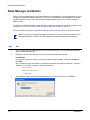
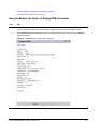
4
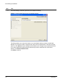
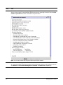
Task
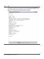
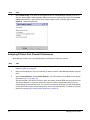
After the installation application finishes loading, it displays the Introduction dialog:
(Note: The screenshots have headers displaying an older version, but the installation screens are
otherwise identical.)
Figure 1 Introduction Screen of Installation Wizard
This dialog introduces the Node Manager installation and describes how to use the program. Click
Next to continue.
Force10 Node Manager Guide, version 1.5.0
19
Node Manager Installation
Step
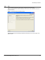
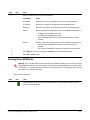
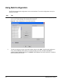
5
Task
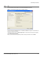
The Node Manager installation application then displays this dialog:
Figure 2 Choose Install Folder Screen of Installation Wizard
This dialog enables you to enter the location on your workstation where you want to install Node
Manager. If you want to install it someplace else, either enter the path directly in the field (as shown
above), or click Choose to open a dialog box that enables you to navigate to your preferrred location.
If you select a different location and then decide that you want to install the files in the default
directory, click Restore Default Folder.
Click Next to continue.
20
Installation
Node Manager Installation
Step
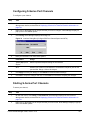
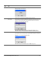
6
Task
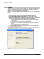
Select the Windows locations where you want the Node Manager launch icons:
Figure 3 Choose Shortcut Folder Screen of Installation Wizard
If you do not like any of the default options, click Other and Choose to navigate to a folder where you
would like to create your shortcuts.
To not create shortcut icons, click Don’t create icons. To create icons for all users of the computer,
select Create Icons for All Users.
When you have finished selecting where you want to create your shortcut icons, click Next.
Force10 Node Manager Guide, version 1.5.0
21
Node Manager Installation
Step
7
Task
For Windows:
After choosing the shortcut locations, choose the installation type. The available installation types for
Windows and UNIX platforms are different. You can either install a standalone version of Node
Manager or integrate Node Manager with HP OpenView NNM.
In Windows, you have three installation options from which to choose (in addition to integration with
FTMS):
•
Standalone version of Node Manager: The Standalone version installs Node Manager as an
independent software product with no requirements. Using this version of Node Manager, you can
view a Force10 chassis and perform various monitoring and management operations.
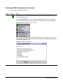
• Node Manager Integrated with HP OpenView Server: In this version, Node Manager is
integrated with HP OpenView Server. In addition to the functionalities provided by the Standalone
version, this integration provides the following additional features to HP OpenView:
• Force10 chassis in the network view of HP OpenView are marked with F10 logos as
Force10 devices.
• Node Manager can be invoked from the HP OpenView menu.
• Alarms from Force10 devices are categorized under "Force10 Alarms" in the Alarms
Window.
• Force10 MIBs are loaded in the HP OpenView Server.
• Node Manager Integrated with HP OpenView Client: With this integration, Node Manager can
be invoked from the HP OpenView menu.
Note: If Node Manager is integrated with HP OpenView Client, HP OpenView Server should also be
integrated with Node Manager to fully utilize the Node Manager functionalities.
22
Installation
Node Manager Installation
Step
8
Task
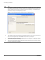
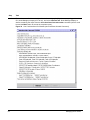
For Solaris:
After choosing the shortcut locations, choose the installation type:
•
•
Standalone version of Node Manager: The Standalone version installs Node Manager as an
independent software product with no requirements. Using this version of Node Manager, you can
view a Force10 chassis and perform various monitoring and management operations.
Node Manager Integrated with HP OpenView: In addition to the functionalities provided by the
Standalone version, the integration provides the following features to HP OpenView:
• Force10 chassis in the network view of HP OpenView are marked with F10 logos as
Force10 devices.
• Node Manager can be invoked from the HP OpenView menu.
• Alarms from Force10 devices are categorized under "Force10 Alarms" in the Alarms
Window.
• Force10 MIBs are loaded in HP OpenView.
Figure 4 Choose Install Set (for Solaris) Screen of Installation Wizard
Note: The screenshot is for an older version, but it is unchanged in the current version.
Force10 Node Manager Guide, version 1.5.0
23
Node Manager Installation
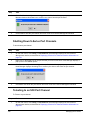
Step
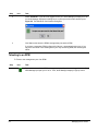
9
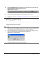
Task
If you choose to integrate Node Manager with HP OpenView, the installer asks for the HP OpenView
Home Directory (the screenshot is of an older version, but it is unchanged in the current version). The
directory should exist and should be a valid HP OpenView Home Directory. The installation will not
proceed if an invalid or non-existing directory is chosen.
Figure 5 Choose HP OpenView Home Directory Screen of Installation Wizard
24
10
The installation program now displays the Pre-Installation Summary for you to verify your choices and
that you have enough disk space. Click Install to write the files to your hard disk.
11
The installation application copies the Node Manager files to your hard disk. The application indicates
its status and how close it is to finishing.
12
When the the Node Manager installation application finishes copying files to your hard disk, it displays
the Install Complete dialog. Click Done.
Installation
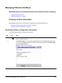
C-Series and E-Series Setup
C-Series and E-Series Setup
To complete the installation, Node Manager requires that you use the FTOS CLI from the C-Series or
E-Series switch to perform two activities for each managed chassis.
Configuring SNMP
Node Manager communicates to each chassis by means of SNMP. This requires that you define an SNMP
community string.
Command Syntax
Command Mode
Usage
snmp-server community
community-string {ro}
CONFIGURATION
Enter the community string you wish to use for
Node Manager with the addition of a read-only
(ro) parameter. Force10 suggests that you use
the same community string for all of your
chassis. If you have previously entered a string
for another SNMP manager and agent, use the
existing string.
Defining a Virtual IP Address
To maintain the IP connection between Node Manager and a chassis in the event of an RPM failover,
Force10 Networks suggests you create a virtual IP address instead of using the IP addresses of the
management interfaces:
Command Syntax
Command Mode
Usage
virtual ip ip-address
CONFIGURATION
Establishes a virtual IP address for a chassis.
Maintains all primary IP connectivity functions,
including SNMP, in the event of a failover. For
details, see the Management Interface section
of the FTOS Configuration Guide.
For more on C-Series and E-Series management, see Managing the S-Series on page 85.
Force10 Node Manager Guide, version 1.5.0
25
S-Series Setup
S-Series Setup
To complete the installation, use SFTOS to configure the management connection on each S-Series
chassis that you want to manage from Node Manager.
Configuring SNMP
Node Manager communicates to each chassis by means of SNMP. This requires that you define an SNMP
community string.
Command Syntax
Command Mode
Usage
snmp-server community name
Global Config
Enter the community string you wish to use for
Node Manager. Force10 suggests that you
use the same community string for all chassis.
If you have previously entered a string for
another SNMP manager and agent, use the
existing string.
Defining the S-Series Management IP Address
Follow the instructions in the Management chapter of the SFTOS Configuration Guide on configuring the
management IP address of an S-Series chassis for accessing it through an IP connection (such as through
Telnet). Briefly:
Command Syntax
Command Mode
Usage
interface managementethernet
Global Config
Invoke the (Config-if-ma)# prompt.
ip address ipaddr subnetmask
(Config-if-ma)# prompt
Set the IP address and subnet mask of the
management interface.
management route default gateway
Global Config
Set the IP gateway of the management
interface.
Note: If you are managing an S50 running SFTOS 2.2 or earlier, use the network parms
command (Global Config mode) to set the management IP address, subnet mask, and default
gateway.
For more on S-Series management, see Managing the S-Series on page 85.
26
Installation
Chapter 3
Using Node Manager
This Chapter contains these topics:
•
•
•
•
•
•
•
•
•
Launching Node Manager
Using the Menus on page 29
Using Keyboard Commands on page 30
Selecting Objects on page 30
Labels, Status Colors, and Indicator LEDs on page 31
The System Message Bar on page 32
Copying and Pasting Text on page 32
Finding Help on page 33
Configuring Refresh Rate and SNMP Properties (Optional) on page 33
Launching Node Manager
Node Manager launches automatically when you double-click on a map icon in FTMS. To launch Node
Manager independently of FTMS, follow these steps:
Step
Icon
Task
1
Navigate to the location where you installed the Node Manager shortcut icon.
2
In Windows, launch and log in to Node Manager.
In UNIX, execute startchassisview.sh under <NM_HOME>/bin folder. NM_HOME is the
default Node Manager Home Directory.
Figure 6 Node Manager Launch Screen
Force10 Node Manager Guide, version 1.5.0
27
Step
3
Icon
Task
Enter the IP address of the chassis you want to view. The SNMP Read Community String
defaults to public and Port Number defaults to 161.
Node Manager uses SNMP v1/v2 as the default version. If you want to configure v3
parameters, select the v3 checkbox.
Click OK to continue or Cancel to exit.
See C-Series and E-Series Setup on page 25 (includes C-Series) and S-Series Setup on
page 26.
4
28
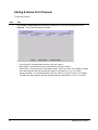
When you click OK, Node Manager displays its main application window and a graphic
representing the chassis as configured (this example shows a thumbnail view of an E300):
Figure 7 E300 Chassis View
Using Node Manager
Step
5
Icon
Task
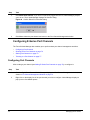
Click File
Login. Node Manager displays this dialog box:
Figure 8 Login to CLI Screen
Enter your CLI Login Name, Password and Enable Password. Click OK to complete the
login process or Cancel to exit and return to the Main Application window.
Note: If you wish to log in by SSH, determine whether SSH is enabled by using the
command show ip ssh. To enable the SSH server, go to Configuration mode and issue
the ip ssh server enable command. Close this dialog box and reopen and select SSH.
Using the Menus
The Node Manager menus allow you to perform a task without knowing the CLI. A picture of the main
Node Manager menu, followed by a description of each menu item, appears below:
Force10 Node Manager Guide, version 1.5.0
29
Figure 9 Node Manager Main Menu
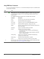
Table 2 Node Manager Main Menu Selections
Menu Item
Description
Title Bar
Above the main menu, the title bar displays “Force10 Node Manager” and the IP address of
the chassis you are viewing in parentheses, along with the standard Microsoft Windows
buttons for minimizing, maximizing, and closing the window.
File Menu
Contains functions that affect either your current session: Telnet to Device, Property Setting,
Login, and Exit.
Config Menu
Enables you to make mass configurations of interfaces (Config Interfaces) and port channels
(Port Channel).
Performance
Templates Menu
View Templates opens the Performance Templates window, where you can create, modify,
and remove the templates that manage the display of charts in the Performance Current Data
Viewer.
View Menu
Redisplays the view of the chassis (Chassis), if you have closed it, or refreshes your screen
(Refresh).
Window Menu
Allows you to switch between windows if you have multiple ones open in the interface.
Help Menu
Provides online access to this document and the Help
About dialog box.
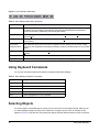
Using Keyboard Commands
You can also use these keyboard commands to navigate within Node Manager:
Table 3 Node Manager Keyboard Commands
Keyboard Entry
Usage
Page Up
Scrolls up one screen
Page Down
Scrolls down one screen
Tab
Moves to the next input field
Shift+Tab
Moves to the previous input field
Ctrl+C
Copies highlighted text to the clipboard
Selecting Objects
You select objects in Node Manager by moving your mouse over them and single-clicking. When you do
so, Node Manager changes the edge of the component to a light turquoise color. An example of this
appears in Figure 10 (the blue line surrounding the graphic indicates that the whole line card is selected):
30
Using Node Manager
Figure 10 Selection Example
Labels, Status Colors, and Indicator LEDs
Force10 uses labels, status colors, and simulations of light-emitting diodes (LEDs) in Node Manager to
communicate information about a chassis and how it is functioning.
Labels
Node Manager uses labels extensively to identify interface components. These labels appear in the same
location on the interface as they do on the actual component in the chassis. See Figure 11 for an example
of the labels on a component:
Figure 11 Labeling Example
Status Colors and Indicator LEDs
The Node Manager uses the same status colors as used by the E-Series to communicate the operational
status of each component. The general meaning of each status color appears in Table 4. For more
information about these colors, please see Appendix B, Alarms, on page 117.
Table 4 Node Manager Colors and their Meaning
Color
Example Meaning
Green
The device is operational and functioning.
Amber
The device is active but a serious condition or fault exists.
Red
The device is active but a hardware failure, temperature
problem or other serious condition exists.
Unlit
This can be one of several issues. The device:
•
•
•
•
has been shut down administratively in Node Manager
is in standby mode
has no electrical power
has a critical temperature condition or other problem
Force10 Node Manager Guide, version 1.5.0
31
The System Message Bar
The System Message Bar displays error and other status messages. It appears at the bottom of the Main
Application window. The purpose of this bar is to alert you to any change in connection status and to
display the text of any error condition that might exist. See Figure 12 for an example of the System
Message Bar. Critical messages appear in red.
Figure 12 Node Manager System Message Bar
Copying and Pasting Text
The Force10 Node Manager enables you to copy and paste interface text to Windows Notepad or similar
programs. The feature works with both data fields and text boxes (Figure 13 has an example of a text box).
Figure 13 Node Manager Text Box
32
Using Node Manager
Note: In Figure 13, note the More button at the bottom of the window. That button is for use when
“--More-- or (q)uit” appears at the bottom of the report. That instruction is for use from the CLI.
To accomplish the same results in Node Manager, click the More or Cancel buttons.
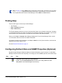
Finding Help
There are three types of online help in Node Manager:
•
•
•
Tool Tip help
Help
Contents assistance
Help
About dialog
Tool Tip help appears whenever you let your mouse pointer linger over an interface component. It displays
in a small text box below your pointer. Its purpose is to identify the component. For example, if you let your
mouse pointer hover over the picture of an SFM, the words Switch Fabric Module appear.
When you click Help
Contents, Node Manager displays this Force10 Node Manager Guide, version
1.5.0 document online in the form of an Adobe Acrobat file.
If you want to contact Force10 Networks, click Help
addresses that may be helpful to you.
About for a list of phone numbers, email and web
See also Related Publications on page 16.
Configuring Refresh Rate and SNMP Properties (Optional)
By default, Node Manager refreshes its display of chassis information every 60 seconds. To make Node
Manager refresh its screen more frequently, or to change your client’s SNMP properties, follow these steps:
Step
1
Icon
Task
In Windows, launch and log in to Node Manager.
In UNIX, execute startchassisview.sh command in the <NM_HOME>/bin folder.
<NM_HOME> is the Node Manager home directory.
Force10 Node Manager Guide, version 1.5.0
33
Step
2
Icon
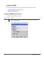
Task
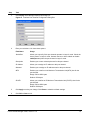
Click File
Property Setting. Node Manager displays this screen:
Figure 14 Property Setting Screen
3
4
34
Enter your selections. See the following table for a description of each field.
Field Name
Usage
Refresh Interval
Defines how often Node Manager polls the chassis to see if it is
functioning. The default is 60 seconds. Enter 0 to disable this
capability.
SNMP Time Out
Sets the number of seconds Node Manager waits for a connection to
the chassis through SNMP before timing out.
SNMP Retry
Times
Defines the number of times Node Manager attempts to connect to
the chassis through SNMP before stopping.
SNMP Port
Number
Sets the UDP port number Node Manager uses to communicate with
the chassis.
SNMP Read
Community
String
Sets the SNMP password in FTMS that Node Manager uses to read
chassis information. The password must match that set on the target
switch.
Click OK to make the change or Cancel to return to main Node Manager window.
Using Node Manager
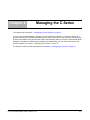
Chapter 4
Managing the C-Series
This chapter has one section — Navigating the C300 Chassis on page 36.
You can connect Node Manager to all types of Force10 Networks switches — C-Series, E-Series, and
S-Series. Because the C-Series C300 switch uses a subset of the same FTOS command set used by the
E-Series, this chapter simply presents the C300 icon that displays when you access a C300 through Node
Manager. For details on monitoring and configuring the C300 switch, you can use the directions in the
E-Series chapter; see Chapter 6, Managing the S-Series, on page 85.
For details on S-Series switch management, see Chapter 6, Managing the S-Series, on page 85.
Force10 Node Manager Guide, version 1.5.0
35
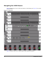
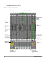
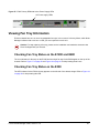
Navigating the C300 Chassis
Figure 15 shows how the Force10 C300 chassis appears in Node Manager (see Figure 16 for a smaller,
annotated image).
Figure 15 C300 Chassis
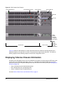
Figure 16 shows the same icon in a smaller image to allow component annotations.
36
Managing the C-Series
Figure 16 C300 Chassis (annotated)
48-Port
Line Card
Fan Tray
RPM Blank
Route
Processor
Module
(RPM)
Line Card
Blanks
4-Port Fiber
Line Card
AC Power Supply
For interpretations of status colors, see Labels, Status Colors, and Indicator LEDs on page 31.
Force10 Node Manager Guide, version 1.5.0
37
38
Managing the C-Series
Chapter 5
Managing the E-Series
All E-Series switches, the management of which is described in this chapter, are supported by Node Manager,
including E300, E600, E600i, and E1200. You can also use the instructions in this chapter for a C-Series
switch. For more on the C-Series switch icon, see Chapter 4, Managing the C-Series, on page 35.
Note: FTMS includes more support for configuration information uploads and software image
downloads; these features are not part of the Node Manager component.
This chapter covers these topics:
•
•
•
•
•
•
•
•
•
•
•
Navigating the E-Series Chassis
Displaying E-Series Chassis Information on page 42
Managing E-Series RPMs on page 46
Managing Line Cards on page 55
Managing E-Series Interfaces on page 61
Managing OSPF Areas on page 66
Managing E-Series Port Channels on page 67
Viewing SFM Information on page 77
Viewing Power Supply Information on page 79
Viewing Fan Tray Information on page 81
Using Bulk Configuration on page 82
Navigating the E-Series Chassis
These images show how Force10 E-Series chassis appear in Node Manager:
•
•
•
The E1200 Chassis View on page 40
The E600 Chassis View on page 41
The E300 Chassis View on page 42
For interpretations of status colors, see Labels, Status Colors, and Indicator LEDs on page 31.
Note: The E600i chassis is not depicted in this book. Its depiction differs from the E600 graphic in
that the SFM graphic has a gray area where the extra SFM modules are in the E600.
Force10 Node Manager Guide, version 1.5.0
39
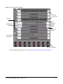
The E1200 Chassis View
Figure 17 E1200 Chassis View Example
Line card label
Fan tray status indicators
Port shut down
administratively
in Node
Manager
Port
operationally down
Port
operationally
down
Major alarm
indicator
LED
Minor alarm
indicator
LED
Primary RPM
indicator LED
Port shut
down administratively in
Node Manager
Line card
status
indicator LED
PEM status
indicator LED
Bad or
missing PEM
Active and
functioning SFM
40
Functioning
inactive (standby)
SFM
Managing the E-Series
The E600 Chassis View
Figure 18 E600 Chassis View Example
Inactive, standby SFM
Fan tray status indicator
PEM status
indicator LED
Line card
label
Bad or
missing PEM
Active and
functioning
port
Active and
functioning
RPM port
Major alarm
LED
Active and
physically
inoperative
port
Minor alarm
LED
Line card port
shut down
administratively in Node
Manager
Line card
status LED
Line card deleted
logically in Node
Manager
Active and functioning
SFM
Force10 Node Manager Guide, version 1.5.0
Port physically
inoperative
Primary RPM
indicator LED
41
The E300 Chassis View
Figure 19 E300 Chassis View Example
Primary RPM indicator LED
Power supply LEDs
Major alarm LED
Minor alarm LED
SFM status LEDs
RPM label
RPM status
indicator LED
Functioning
RPM port
Line card
status LED
Fan tray
status LED
Line card
label
Port shut
down administratively in
Node Manager
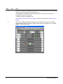
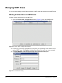
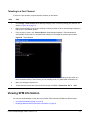
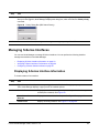
Displaying E-Series Chassis Information
Node Manager enables you to display chassis information in various ways. Right-click the area next to the
fan tray status icons. From the popup menu, click Current Statistics to select from the following choices
(as shown in Figure 20):
•
•
•
Figure 20
42
Chassis_CPU_Utilization
Chassis_Memory_Utilization
Chassis_RPM_Memory_Utilization
Chassis Current Statistics
Managing the E-Series
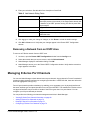
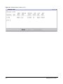
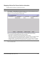
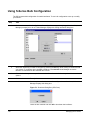
Whichever of the options you select, the Performance Current Data Viewer window opens (Figure 21 on
page 44). The window displays an empty bar chart at first, but then begins to display data based upon the
default settings for the selected report. You can select an alternate chart type from the Chart Options
section at the bottom of the window. Besides Bar Chart, you can select Line Chart or XY Line Chart.
Note: The window is divided into three panes. To give more room to the graph, click the triangular
down button located at the top left of one of the two lower panes. You can then expand the lower
panes with the triangular up button.
Below the chart is a table that reports the data collected at each data collection point in the collection
interval. You can modify the collection interval in the Poll Interval field (specified in seconds), which is
near the bottom of the window.
For chart input, you can select from the following parameters, which are in the bottom pane of the window:
•
•
•
•
•
•
•
•
Average: The data collected over the specified time period is added together, and the number of
sampling period values is divided by the added value. The sampling period value is used as the poll
interval for current monitoring. 15 minutes is used for history monitoring.
Nth Percentile: This function needs two parameters: time period (enter a value in seconds in the
Duration field) and percentile value (enter in the Percentile field). When this function is applied, the
data plotted is the percentile value of the number of samples collected over the specified time period.
Max Nth Percentile: This function is similar to Nth Percentile, but the sample values collected over the
specified time period are sorted in descending order, and the given Nth percentile value is calculated.
Min Nth Percentile: This function is similar to Nth Percentile, but the sample values collected over the
specified time period are sorted in ascending order, and the given nth percentile value is calculated.
Cumulative Data: The data plotted in the graph is the data value at any nth interval, and is the sum of
the data values collected in the previous n – 1 intervals.
Max Value in Set: The maximum value of the data collected over the specified time period is plotted in
the graph.
Min Value in Set: The minimum value of the data collected over the specified time period is plotted in
the graph.
None: The raw data collected from the node is plotted as such.
To start collecting data with a new parameter, click Apply. You can start and stop polling with the Start
Polling/Stop Polling button, which is near the bottom of the window (When polling starts, the Stop Polling
button replaces the Start Polling button.)
Force10 Node Manager Guide, version 1.5.0
43
Figure 21 Performance Current Data Viewer
44
Managing the E-Series
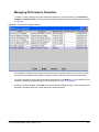
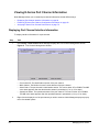
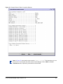
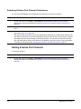
Managing Performance Templates
To delete or modify existing performance monitoring templates or create templates, click Performance
Template Template Viewer. The Performance Templates window opens, an example of which is shown
in Figure 22.
Figure 22 Performance Templates Window
As indicated by the buttons at the bottom of the Performance Templates window, you can create, modify,
and remove the templates that manage the display of charts in the Performance Current Data Viewer.
To modify a template, you can either select the template and then click Modify, or you can double-click the
template. The Modify Templates dialog box opens, as shown in Figure 23 on page 46.
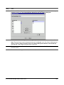
Similarly, to create a template, click Create. The Create Templates dialog box opens, which is basically like
the Modify Templates dialog box, except without any default selections.
Force10 Node Manager Guide, version 1.5.0
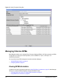
45
Figure 23 Modify Templates Dialog Box
Managing E-Series RPMs
Node Manager enables you to manage Route Processor Modules (RPMs). All E-Series chassis use RPMs
to segregate core routing and control operations, such as SNMP, CLI, Layer 2, and Layer 3, for
redundancy and speed.
You can perform these RPM management activities with Node Manager:
•
•
Viewing RPM Information on page 46
Configuring RPMs on page 52
Viewing RPM Information
In addition to the show commands introduced in Using RPM Show Commands on page 48, Node Manager
allows you to research RPM configuration data several different ways:
•
•
46
Using the Module Info Option to Display RPM Information on page 47
Using RPM Show Commands on page 48
Managing the E-Series
•
•
Examining RPM Configuration Information on page 50
Analyzing RPM Performance on page 51
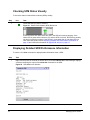
Using the Module Info Option to Display RPM Information
Step
Task
1
Right-click inside the picture of the RPM you wish to examine. (Do not click the management port icon
or your results will be different.) Node Manager displays a pop-up menu of available options.
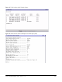
2
Select Module Info. Node Manager displays a window containing the output from the show rpm
number command:
Figure 24 RPM Module Info (show rpm Command)
Force10 Node Manager Guide, version 1.5.0
47
Using RPM Show Commands
You can use Node Manager to launch CLI show commands and display the output in a scrollable window.
To access these commands:
Step
Task
1
Right-click the icon of the Primary RPM (the one with the lit Primary LED). Do not click the
management port icon or your results will be different. If you have not yet logged into the
CLI, Node Manager prompts you to do so. Node Manager displays a pop-up menu of
available options.
2
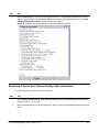
Select Show. Node Manager displays a menu of available show commands:
Command
Description
alarms
Shows the minor and major alarms set for the RPM.
bootvar
Shows the RPM’s bootvar configuration.
chassis brief
Displays the output from the show chassis brief command.
environment
Reports the RPM’s temperature, voltage, and so forth.
logging
Shows the logging settings and system messages contained in the
RPM’s internal buffer.
redundancy
Reports current RPM redundancy information.
Process
Displays a menu with two sub-options:
•
•
3
48
CPU: Shows CPU usage information for the RPM based on
running processes.
Memory: Displays the memory usage information for the RPM
based on running processes.
running-config
Displays current configuration information and indicates any
changes from the default values.
startup-config
Shows the startup configuration file, if present.
version
Displays version and startup information about the chassis.
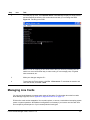
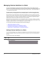
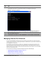
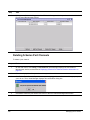
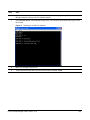
Select the name of the command. Node Manager displays a window containing the output
for the command. See Figure 25 on page 49 for an example.
Managing the E-Series
Figure 25 Show Chassis Brief Example Output
Force10 Node Manager Guide, version 1.5.0
49
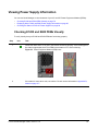
Examining RPM Configuration Information
To review RPM configuration information:
Step
Icon
Task
1
Right-click the icon for the RPM’s management port. Node Manager displays a pop-up
menu of available options.
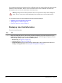
2
Select Show Config. Figure 26 is a screenshot showing that selection on the popup
menu overlaid on a partial view of the selected management port on the selected RPM.
Figure 26 RPM Popup Menu, Show Config
If you have not yet logged into the CLI, Node Manager prompts you to do so. After you do,
Node Manager displays a window containing the output from the show config command
for the RPM management port:
Figure 27 Show Config: RPM
50
Managing the E-Series
Analyzing RPM Performance
Node Manager enables you to plot the performance of each RPM graphically:
Step
Task
1
Right-click the icon for the Primary RPM’s management port. Node Manager displays a
pop-up menu of available options.
2
Select Current Statistics
Port_Traffic_Statistics. Figure 28 is a screenshot showing
that selection on the popup menu overlaid on a partial view of the selected management
port on the selected RPM.
Figure 28 RPM Popup Menu, Current Statistics
Node Manager displays the Performance Current Data Viewer window, with data for the
selected RPM displayed on the graph and table. The window displays an empty bar chart
at first, but then begins to display data based upon the default settings for the selected
report. You can select an alternate chart type from the Chart Options section at the bottom
of the window, along with a variety of input parameters. For details on modifying display
parameters on the window, see Displaying E-Series Chassis Information on page 42
Force10 Node Manager Guide, version 1.5.0
51
Configuring RPMs
The Force10 Node Manager also enables you to perform these RPM configuration activities:
•
•
•
Configuring RPM Management Ports on page 52
Shutting Down RPM Ports on page 53
Telneting to an RPM on page 54
Configuring RPM Management Ports
To configure the management port on an RPM:
Step
52
Icon
Task
1
Right-click the icon for the RPM management port. Node Manager displays a pop-up
menu of available options.
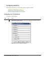
2
Select Config. Node Manager displays this dialog box:
Managing the E-Series
Step
Icon
3
Task
Enter your selections. You have these options:
Field Name
Usage
Description
Enables you to enter a descriptive text for the management port.
IP Address
Allows you to assign an IP address to the management port.
Netmask
Enables you to assign an IP address mask to the management port.
Speed
Sets the speed of the management port. The available list options are:
•
•
•
Duplex
10 Mbps: Ten megabits per second.
100 Mbps:100 megabits per second.
Auto: Node Manager sets the speed to the maximum the RPM
permits.
Sets the mode of the management port. The available list options are:
•
•
half: Sets the management interface to transmit only in one
direction.
full: Sets the management interface to transmit in both directions.
4
Click Apply to make your change. Click Reset to reload the default settings.
5
Click OK or Close to exit.
Shutting Down RPM Ports
Warning: If you use this feature to shut down the active RPM port and you do not have a second
RPM installed for failover, you cannot access the chassis from Node Manager or from within Telnet
to re-enable it. If you shut down the active port on a chassis with only one RPM, the only way you
can restart it is to reboot the chassis.
To shut down a RPM port:
Step
1
Icon
Task
Right-click the icon for the RPM’s management port. Node Manager displays a pop-up
menu of available options.
Force10 Node Manager Guide, version 1.5.0
53
Step
Icon
2
Task
Select Shutdown. If you have not logged into the CLI, Node Manager prompts you to do
so. Node Manager displays this dialog box to confirm your wish to shut down the port:
Figure 29 Port Shutdown Confirmation Dialog Box
3
Click Yes to shut down the RPM’s management port and the RPM.
If you have a secondary RPM configured for failover, it automatically takes over. If you
only have one RPM or are shutting down your only functioning RPM, the chassis goes
offline.
Telneting to an RPM
To Telnet to the management port of an RPM:
Step
1
54
Icon
Task
Right-click the icon for the RPM’s management port. If you have not logged into the CLI,
Node Manager prompts you to do so. Then, Node Manager displays a pop-up menu.
Managing the E-Series
Step
2
Icon
Task
From the pop-up menu, click Telnet to Device. Node Manager displays a Telnet window
and automatically invokes the CLI commands that enable you to manage the RPM.
Figure 30 Telnetting to an RPM
Note: You can do anything in this Telnet window that you can do by telnetting into the
switch in a more conventional way. In other words, you can manage ports, run global
show commands, etc.
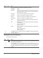
3
Make your changes using the CLI.
4
To terminate the Telnet session, click File
close the window, click File
Exit.
Disconnect. To terminate the session and
Managing Line Cards
You can use Node Manager to manage many types of line cards. For information about the line cards
Node Manager supports, refer to Appendix A, Supported Devices on page 113.
E-Series line cards are hot-swappable. You can add, replace, or remove a card without interrupting system
power or system operations. No additional configuration is necessary if you insert a new line card into a
slot occupied by a blank panel or if you hot-swap identical card types.
Force10 Node Manager Guide, version 1.5.0
55
If you replace an existing line card with one from a different series, you must configure the system with the
updated line card information. Refer to the CLI Commands section of the installation document that
accompanies each card for more information about this process.
Warning: Always wear an ESD-preventative wrist or foot-ground heel strap when handling line
cards. After you remove the original packaging, place components on an anti-static surface.
You can perform these line card management activities with Node Manager:
•
•
•
Displaying Line Card Information on page 56
Adding Logical Line Cards on page 59
Deleting Logical Line Cards on page 60
Displaying Line Card Information
To view line card information:
Step
1
Task
Right-click inside the picture of the line card you wish to examine. (Do not click a port icon or your
results will be different.) If you have not yet logged into the CLI, Node Manager prompts you to do so.
Node Manager displays a pop-up menu of available options:
•
•
•
56
Module Info (see Figure 31 on page 57)
Interface Info (see Figure 32 on page 58)
Config Interfaces (This menu item invokes a window that is also invoked from the main menu:
Config
Config Interfaces. See Using Bulk Configuration on page 82.)
Managing the E-Series
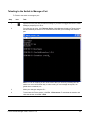
Step
2
Task
For an overview of a particular line card, right-click the line card graphic and select Module Info.
Node Manager displays a window containing the output from the show linecard number command
(You can also access the report by double-clicking the line card graphic):
Figure 31 Line Card Module Info Window (show linecard Command)
Force10 Node Manager Guide, version 1.5.0
57
Step
3
Task
To view the status of a line card, right-click the line card graphic (If you have not yet logged into the
CLI, Node Manager prompts you to do so), and select Interface Info. Node Manager displays a
window containing the output from the show interfaces linecard number command (use the scroll
bar and the More button to access the complete report):
Figure 32 Line Card Interface Info Window (show interfaces linecard Command)
58
Managing the E-Series
Adding Logical Line Cards
Note: Node Manager does not support all Force10 line cards. For information about the line cards
Node Manager does support, refer to Appendix A, Supported Devices on page 113.
You can only add logical line cards in Node Manager. Logical line cards are those that only exist in the
software and that do not exist physically in the chassis.
To add a logical line card in Node Manager:
Step
1
Task
Right-click on the picture of any empty slot. Node Manager indicates these by displaying a picture of
a blank panel. Node Manager displays a pop-up menu of available options.
Figure 33 Empty Slot
2
Select Add Linecard. If you have not previously logged into the CLI, Node Manager prompts you to
do so. After you have logged in, Node Manager displays this dialog box:
Figure 34 Add Linecard Dialog Box
Node Manager automatically proposes the number of the slot you clicked in the Slot list and a line
card in the Card Type list.
3
From the Slot list, select the location where you wish to add the line card. Select a different number if
you wish to insert the card in a slot other than the default.
Force10 Node Manager Guide, version 1.5.0
59
Step
4
Task
From the Card Type list, select the type of line card you wish to install. Once you select a line card,
Node Manager displays a grayed-out version of it in the slot:
Figure 35 Blank Line Card Icon
5
Follow the directions that accompany the line card to install it physically in the slot.
6
Configure the line card. Refer to Managing E-Series Interfaces on page 61 for more information about
this process.
Deleting Logical Line Cards
You can only delete logical line cards in the Force10 Node Manager. Logical line cards are those that only
exist in the software and that do not exist physically in the chassis.
To delete a logical line card in Node Manager:
Step
Task
1
Right-click the picture of the grayed-out line card you wish to delete. (Do not click a port icon or your
results will be different.) Node Manager displays a pop-up menu of available options.
2
Select Delete Linecard. If you have not previously logged into the CLI, Node Manager prompts you
to do so. After you have logged in, Node Manager displays this dialog box:
Figure 36 Delete Line Card Dialog Box
3
60
Click Yes. Node Manager removes the card from the display.
Managing the E-Series
Managing E-Series Interfaces
Node Manager enables you to manage logical interfaces. Logical interfaces are software connections to
hardware line card ports. You can perform the following interface management activities in Node Manager:
•
•
Viewing Interface Information
Configuring Interfaces on page 63
Viewing Interface Information
Node Manager enables you to view interface configuration data several different ways:
•
•
Examining Interface Configuration Information on page 61
Analyzing Interface Performance on page 62
Examining Interface Configuration Information
To research logical interface configuration information:
Step
Icon
Task
1
Right-click the icon of the port that you wish to examine. Node Manager displays a pop-up
menu of available options.
2
Click Show Config. If you have not yet logged into the CLI, Node Manager prompts you
to do so. Node Manager displays a window containing the output from the show config
CLI command for that port:
Figure 37 Show Config: Linecard
Force10 Node Manager Guide, version 1.5.0
61
Analyzing Interface Performance
Node Manager enables you to plot the performance of each line card port graphically using a variety of
techniques. To do so:
Step
Task
1
Right-click the icon of the line card port you wish to examine. If you have not yet logged
into the CLI, Node Manager prompts you to do so. Node Manager displays a pop-up menu
of available options.
2
Select Current Statistics
Port Traffic Statistics. The Performance Current Data
Viewer window opens (see Figure 21 on page 44).
Just as described previously for the chassis, selected RPM, and selected line card, the
window displays an empty bar chart at first, but then begins to display data based upon
the default settings for the selected report. You can select an alternate chart type from the
Chart Options section at the bottom of the window, along with a variety of input
parameters. For details on using the window, see Displaying E-Series Chassis Information
on page 42.
62
Managing the E-Series
Configuring Interfaces
Node Manager also enables you to perform these interface configuration activities:
•
•
•
Configuring Line Card Interfaces on page 63
Shutting Down Line Card Interfaces on page 64
Telneting to the Switch to Manage a Port on page 65
Configuring Line Card Interfaces
To configure a line card interface:
Step
Icon
Task
1
Right-click the icon of the line card port you want to configure. Node Manager displays a
pop-up menu of available options.
2
Select Config. Node Manager displays this dialog box:
Figure 38 Line Card Configuration Dialog Box
Force10 Node Manager Guide, version 1.5.0
63
Step
Icon
3
Task
Enter your selections. See this table for a description of each field.
Field Name
Usage
SwitchPort
Specify if this interface operates in Layer 2 mode. Check the box to
place it in Layer 2 mode. Uncheck the box or leave it blank to place
the interface in Layer 3 mode.
Description
Allows you to enter a descriptive text for this interface.
IP Address
Permits you to assign an IPv4 address to the port.
Netmask
Permits you to assign an IPv4 address mask to the interface.
IPV6 Address
Permits you to assign an IPv6 address to the port.
Prefix
Permits you to assign an IPv6 address mask to the interface. Enter
the prefix in bits: <0-128>
MTU
Enables you to enter a link Maximum Transmission Unit (MTU) size
for the interface.
Range: 594 to 9252 bytes
Default: 1554 bytes
IP MTU
Allows you to enter an IP Maximum Transmission Unit (IP MTU) size
for the interface.
Range: 594 to 9252 bytes
Default: 1500 bytes
4
Click Apply to make your change or changes. Click Reset to reload the default settings.
5
Click OK or Close to exit.
Shutting Down Line Card Interfaces
To shut down a line card interface:
Step
64
Icon
Task
1
Right-click the icon of the line card port you want to shut down. Node Manager displays a
pop-up menu of available options.
2
Select Shutdown. If you have not logged into the CLI, Node Manager prompts you to do
so. Node Manager displays a confirmation box to confirm your wish to shut down the port:
3
Click Yes. Node Manager shuts down the port and returns you to the Main Application
window.
Managing the E-Series
Telneting to the Switch to Manage a Port
To Telnet to the switch to manage a port:
Step
Icon
Task
1
Right-click on the port that you want to manage. If you have not logged into the CLI, Node
Manager prompts you to do so.
2
From the pop-up menu, click Telnet to Device. Node Manager displays a Telnet window
and automatically invokes the CLI commands that enable you to manage the selected
port.
Note: You can do anything in this Telnet window that you can do by telnetting into the
switch in a more conventional way. In other words, you can manage other ports, run
global show commands, etc.
3
Make your changes using the CLI.
4
To terminate the Telnet session, click File
close the window, click File
Exit.
Force10 Node Manager Guide, version 1.5.0
Disconnect. To terminate the session and
65
Managing OSPF Areas
You can use Node Manager to add E-Series networks to OSPF areas and delete them from OSPF areas.
Adding a Network to an OSPF Area
To add an E-Series switch network to an OSPF area:
1
Open the Router OSPF Configuration window (Figure 39) from the Config menu:
Figure 39 Router OSPF Configuration Window
2
Inspect the current area associations to verify that you are adding a new network to the
correct OSPF area. Click Details to display the output of the show ip ospf command.
3
Click Add Network. Node Manager displays the Add Network dialog box:
Figure 40 Add Network Dialog
66
Managing the E-Series
4
Enter your selections. See this table for a description of each field.
Table 5 Add Network Dialog Fields
Field Name
Usage
Process
Permits you to create an OSPF instance (the equivalent of the
router-ospf process-id command). If the target switch already has
an instance of an OSPF process running, this field is preset with
that process ID.
IP Address
Assign an IPv4 address.
Netmask
Assign a subnet mask in CIDR format.
Area ID
Assign a new area a unique integer ID. If the area is new, FTMS
creates the area.
5
Click Apply to make your change or changes, or click Reset to reload the default settings.
6
Click OK or Close to exit. Verify that your changes appear in the Router OSPF Configuration
window.
Removing a Network from an OSPF Area
To remove an E-Series network from an OSPF area:
1
As above, open the Router OSPF Configuration window from the Config menu.
2
Select the network that you want to remove, and click Delete Network.
3
Node Manager displays a confirmation dialog. Click OK.
4
Node Manager returns you to the Router OSPF Configuration window. Verify that the network no
longer appears in the table.
Managing E-Series Port Channels
You can use Node Manager to both add and remove port channels. A port channel is Force10’s method of
grouping multiple physical interfaces into a single logical interface. In IEEE 802.3ad, these are referred to
as a Link Aggregation Group (LAG).
Force10 port channels provide redundancy by enabling you to aggregate up to 16 physical interfaces of
the same interface type and speed interfaces into one logical interface. This enables the E-Series to have
one physical interface carry the traffic of another if the former goes down in a port channel. You can
configure up to 32 port channels per chassis.
You can perform the following port channel management activities in Node Manager:
•
•
•
•
Viewing E-Series Port Channel Information on page 68
Adding E-Series Port Channels on page 72
Deleting E-Series Port Channels on page 73
Configuring E-Series Port Channels on page 74
Force10 Node Manager Guide, version 1.5.0
67
Viewing E-Series Port Channel Information
Node Manager allows you to research port channel information several different ways:
•
•
•
Displaying Port Channel Interface Information on page 68
Examining E-Series Port Channel Configuration Information on page 69
Analyzing E-Series Port Channel Performance on page 70
Displaying Port Channel Interface Information
To display interface information for a port channel:
Step
1
Task
Click Config
Port Channel. Node Manager displays the Port Channel Management window:
Figure 41 Port Channel Management Window
This dialog box displays the:
•
•
•
•
2
68
Port channel ID: The identification number of the port channel
MAC Address: The Medium Access Control address of the port channel
Admin Status: The port channel’s administrative status. This can be either UP or DOWN. The MIB
value status appears after the administrative status in parenthesis (1 for up, 2 for down).
Operational Status: The operational status of the port channel. This can be either UP or DOWN.
The MIB value status appears after the operational status in parenthesis (1 for up, 2 for down).
Right-click the display line of the port channel you wish to examine. Node Manager displays a pop-up
menu of available options.
Managing the E-Series
Step
3
Task
Select Interface Info. If you have not yet logged into the CLI, Node Manager prompts you to do so.
After you have logged in, Node Manager displays a dialog box containing the output from the show
interface port-channel number command for the port channel.
Figure 42 Interface Info Window (show interface port-channel Command)
Examining E-Series Port Channel Configuration Information
To review configuration information for a port channel:
Step
Task
1
Select Config
Port Channel. Node Manager displays the Port Channel Management window as
shown in Figure 41 on page 68.
2
Right-click the display line of the port channel you wish to examine. Node Manager displays a pop-up
menu.
Force10 Node Manager Guide, version 1.5.0
69
Step
3
Task
Select Show Config. If you have not yet logged into the CLI, Node Manager prompts you to do so.
After you have logged in, Node Manager displays a dialog box containing the output from the show
config command for the port channel. Some sample output for this command appears below:
Figure 43 Show Config Window
Analyzing E-Series Port Channel Performance
Node Manager enables you to plot graphically the performance of each port channel.
Step
Task
1
Select Config
Port Channel. Node Manager displays the Port Channel Management window, as
shown in Figure 41 on page 68.
2
Right-click the display line of the port channel you wish to examine. Node Manager displays a pop-up
menu.
3
Select Current Statistics
Port Traffic Statistics. The Performance Current Data Viewer window
opens (see Figure 21 on page 44).
The chart window is the same one used for ports, the chassis, selected RPM, and selected line card.
The window displays an empty bar chart at first, but then begins to display data based upon the
default settings for the selected report. You can select an alternate chart type from the Chart Options
section at the bottom of the window, along with a variety of input parameters. For details on using the
window, see Displaying E-Series Chassis Information on page 42.
70
Managing the E-Series
Step
4
Task
Use the choices at the bottom of the window to select the parameters of graph you wish to view.
If you wish, you can change the appearance of the graph. For example, you can enter a different
number of seconds in the Polling Interval field. You can also choose a different presentation method
from the Graph Type list. The available options are:
• Line (default)
• Bar
• XY Step Plot
To view the X-Y coordinate values of a point on the graph, move your mouse to that location. (Node
Manager displays the coordinates of your mouse pointer once you move it into the dialog box.)
To view help documentation, click the Help icon.
5
To return to the main Node Manager window, click the Close icon (top right).
You can also select the window you want from the Window menu.
Force10 Node Manager Guide, version 1.5.0
71
Adding E-Series Port Channels
To add a port channel:
Step
1
Task
Click Config
Port Channel. Node Manager displays the Port Channel Management window.
Figure 44 Port Channel Management Window
This dialog box displays the:
•
•
•
•
72
Port channel ID: The identification number of the port channel.
MAC Address: The Medium Access Control address of the port channel.
Admin Status: The port channel’s administrative status. This can be either UP or DOWN. The MIB
value status appears after the administrative status in parenthesis (1 for up, 2 for down).
Operational Status: The operational status of the port channel. This can be either UP or DOWN.
The MIB value status appears after the operational status in parenthesis (1 for up, 2 for down).
Managing the E-Series
Step
2
Task
Click the Add Port Channel button. If you have not previously logged into the CLI, Node Manager
prompts you to do so. Then, Node Manager displays this dialog box:
Figure 45 Add Port Channel Dialog Box
3
Enter the ID number you wish to assign to the port channel in the Channel ID field.
4
Select the description of the interface and port from the Available Item field. The Add button
becomes active.
5
Click Add. Node Manager moves the line card to the Selected Item field.
6
Click OK. Node Manager adds the port channel to the list in the Port Channel Management window.
Deleting E-Series Port Channels
To delete a port channel:
Step
Task
1
Click Config
Port Channel. Node Manager displays the Port Channel Management window, as
shown in Figure 44 on page 72.
2
Select the display line of the port channel that you want to delete.
Force10 Node Manager Guide, version 1.5.0
73
Step
Task
3
Click Delete Port Channel. If you have not previously logged into the CLI, Node Manager prompts
you to do so. Then, Node Manager displays the Confirm dialog.
Figure 46 Confirm Delete Port Channel Dialog
4
Click Yes to delete the port channel and return to the Port Channel Management window.
Configuring E-Series Port Channels
The Force10 Node Manager also enables you to perform these port channel management activities:
•
•
•
•
Configuring Port Channels
Shutting Down Port Channels on page 76
Starting Port Channels on page 76
Telneting to a Port Channel on page 77
Configuring Port Channels
After creating a port channel (see Adding E-Series Port Channels on page 72), to configure it:
Step
74
Task
1
Click Config
Port Channel. Node Manager displays the Port Channel Management window, as
shown in Port Channel Management Window on page 72.
2
Right-click on the display line of the port channel you wish to configure. Node Manager displays a
pop-up menu of available options.
Managing the E-Series
Step
3
Task
Click Config. Node Manager displays this dialog box:
Figure 47 Interface Port Channel Configuration Dialog Box
4
Enter your selections. You have these options.
Field Name
Usage
SwitchPort
Allows you to specify if this port channel operates in Layer 2 mode. Check the
box to place it in Layer 2 mode. Uncheck the box or leave it blank to disable
switchport and place the port channel in Layer 3 mode.
Description
Enables you to enter a descriptive text for this port channel.
IP Address
Allows you to assign an IP address to this port channel.
Netmask
Enables you to assign an IP address mask to the port channel.
MTU
Enables you to define a link Maximum Transmission Unit (MTU) size for the
port channel.
Range: 594 to 9252 bytes
Default: 1554 bytes
IP MTU
Allows you to define an IP Maximum Transmission Unit (IP MTU) size for the
port channel.
Range: 594 to 9252 bytes
Default: 1500 bytes
5
Click Apply to make your change. Click Reset to reload the default settings.
6
Click OK or Close to exit.
Force10 Node Manager Guide, version 1.5.0
75
Shutting Down Port Channels
To shut down a port channel:
Step
Task
1
Click Config
Port Channel. Node Manager displays the Port Channel Management window, as
shown in Figure 45 on page 73.
2
Right-click on the display line of the port channel you wish to shut down. Node Manager displays a
pop-up menu of available options.
3
Click Shutdown. If you have not logged into the CLI, Node Manager prompts you to do so. Then,
Node Manager displays this dialog box to confirm your wish to shut down the port:
Figure 48 Port Shutdown Confirmation Dialog Box
4
Click Yes to shut down the port channel and return to the Port Channel Management window.
Starting Port Channels
To start a port channel;
Step
Task
1
Click Config
Port Channel. Node Manager displays the Port Channel Management window, as
shown in Figure 44 on page 72.
2
Right-click on the display line of the port channel you wish to start. Node Manager displays a pop-up
menu of available options.
3
Click No Shutdown. If you have not logged into the CLI, Node Manager prompts you to do so. Node
Manager displays this dialog box to confirm your wish to start the port:
Figure 49 Port Startup (no shutdown Command) Confirmation
4
76
Click Yes to start the port channel and return to the Port Channel Management window.
Managing the E-Series
Telneting to a Port Channel
To telnet to a port channel (a logical interface address) on the switch:
Step
Task
1
Click Config
Port Channel. Node Manager displays a list of currently existing port channels, as
shown in Figure 45 on page 73.
2
Right-click the display line of the port channel to which you want to telnet. Node Manager displays a
pop-up menu of available options.
3
From the pop-up menu, click Telnet to Device. Node Manager displays a Telnet window and
automatically invokes the CLI commands that enable you to manage the selected port channel.
Figure 50 Telnet Window
Note: You can do anything in this Telnet window that you can do by telnetting into the switch in a
more conventional way. In other words, you can manage ports, run global show commands, etc.
4
Make your changes using the CLI.
5
To terminate the session and close the Telnet window, click File
Disconnect, File
Exit.
Viewing SFM Information
You can use Node Manager to learn about your Switch Fabric Modules (SFMs) two different ways:
•
•
Checking SFM Status Visually on page 78
Displaying Detailed SFM Performance Information on page 78
Force10 Node Manager Guide, version 1.5.0
77
Checking SFM Status Visually
To check the status of switch fabric modules (SFMs) visually:
Step
Icon
1
Task
Locate the SFM you want to examine.
Figure 51 Switch Fabric Module (SFM) Status Icon
If both the Active and Status LEDs are green, the SFM is functioning properly. If the
Status LED is green and the Active is not, and the SFM is in Slot 8, the SFM is a standby
unit and is functioning properly. If the SFM is in a slot other than 8, and either LED is a
color other than green, refer to Displaying Detailed SFM Performance Information on
page 78 and consult the information in Appendix B, Alarms on page 117.
Displaying Detailed SFM Performance Information
To launch a CLI show command to display detailed information about a SFM:
Step
1
Task
Right-click the picture of the SFM, as shown above, and select Module Info. Node Manager displays
a window containing the output of the show sfm command for the SFM:
Figure 52 SFM Module Info Window
78
Managing the E-Series
Viewing Power Supply Information
You can use Node Manager to view the status of your AC and DC Power Equipment Modules (PEMs).
•
•
•
Checking E1200 and E600 PEMs Visually on page 79
Displaying More E1200 and E600 Power Supply Information on page 80
Checking the Status of E300 AC Power Supplies on page 80
Checking E1200 and E600 PEMs Visually
To verify visually that your E1200 and E600 PEMs are functioning properly:
Step
1
Icon
Task
Locate the Status LED. If it is green, the PEM is functioning properly. If the PEM appears
like either image below, there is no PEM in that location or it is not functioning:
Figure 53 Power Equipment Module (PEM) Icons
2
If the status is some other color, consult the CLI and use the information in Appendix B,
Alarms on page 117.
Force10 Node Manager Guide, version 1.5.0
79
Displaying More E1200 and E600 Power Supply Information
To display additional E1200 and E600 power supply information:
Step
1
Task
Right-click the picture of the PEM and select Module Info. Node Manager displays this window:
Figure 54 PEM Module Info Window
This window displays the following list of attributes and their values:
•
•
PEM Operation Status: This can be either UP or DOWN. The MIB value status appears after the
operational status in parenthesis (1 for up, 2 for down)
PEM Type: This can be either AC or DC. The MIB value status appears after the operational
status in parenthesis (1 for up, 2 for down).
Checking the Status of E300 AC Power Supplies
To verify the operating status of the E300 AC power supplies, check the color of the power supply LEDs on
the Primary RPM. The E300 requires a minimum of three AC power supplies to function. If all four power
supply LEDs are green (PS0 through PS3), all your AC power supplies are working properly. If not, consult
the information in Appendix B, Alarms on page 117.
80
Managing the E-Series
Figure 55 E300 Primary RPM with Active Power Supply LEDs
AC Power supply LEDs
Viewing Fan Tray Information
E-Series chassis have one or more hot-swappable fan trays. In the event of a fan tray failure, which Node
Manager indicates with a red icon or LED, you must replace the entire unit.
Caution: For help replacing a fan tray, please see the installation and maintains document that
Force10 shipped with your chassis.
Checking Fan Tray Status on the E1200 and E600
The icon indicators for fan trays on the E1200 and the single fan tray for the E600 appear on the top of the
chassis. Refer to Figure 17 on page 40 and Figure 18 on page 41 for help locating these icons.
Checking Fan Tray Status on the E300
The LED indicator for the E300’s fan tray appears on the left side of the chassis image. Refer to Figure 19
on page 42 for help locating this LED.
Force10 Node Manager Guide, version 1.5.0
81
Using Bulk Configuration
The E-Series supports bulk configuration for line card interfaces. To use bulk configuration to set up or
modify your chassis:
Step
1
Task
Click Config
Interfaces. If you have not previously logged into the CLI, Node Manager prompts
you to do so. Node Manager then displays this dialog box:
Figure 56 Bulk Configuration for Line Card Interfaces
2
82
To add one interface at a time, select the interface and then click Add. To add several interfaces at
once, press the Ctrl key while clicking on each item with your mouse, and then click Add. To
configure all the available interfaces, click Add All. Node Manager moves the interface or interfaces
into the Selected Item column.
Managing the E-Series
Step
3
Task
Select the function you want to perform on the interfaces from the Action list. You have these options:
Command
Description
shutdown
Use this option to disable the interfaces. If you click shutdown, Node Manager
displays this dialog box:
Figure 57 Shutdown Dialog Box
Leave the box checked and click OK to shut down the interfaces.
no shutdown
Use this option to enable the interfaces. If you click no shutdown, Node
Manager displays this dialog box:
Figure 58 Switchport Dialog Box
Leave the box unchecked and click OK to start the interfaces.
switchport
Use this option to place the interfaces in Layer 2 mode. If you click
switchport, Node Manager displays this dialog box:
Figure 59 Switchport Dialog Box
To put the interfaces in Layer 2 mode, leave the box checked and click OK.
Force10 Node Manager Guide, version 1.5.0
83
Step
Task
MTU setting
Use this option to define a link Maximum Transmission Unit (MTU) size for the
interface. If you select this option, Node Manager displays this dialog box:
Figure 60 MTU Dialog Box
Enter the Link MTU setting you want to assign to the interfaces. Your
permissible range is 594 to 9252 bytes. If you do not enter a value, Node
Manager uses a default Link MTU value of 1554 bytes for each interface. Click
OK to complete the action.
command
Use this option to enter brief CLI commands that apply to all of the interfaces you
selected. If you choose this option, Node Manager displays this dialog box:
Figure 61 CLI Command Dialog Box
Enter the text of your CLI command and click OK to carry it out.
84
Managing the E-Series
Chapter 6
Managing the S-Series
This chapter describes how to use Node Manager to manage and monitor S-Series switches.
Note: FTMS adds S-Series software image download capability, which is not part of the Node
Manager component.
This chapter covers the following topics:
•
•
•
•
•
•
•
Navigating the S-Series Switch
Displaying S-Series Chassis Information on page 86
Managing S-Series Switches in a Stack on page 90
Managing S-Series Interfaces on page 93
Configuring S-Series Interfaces on page 97
Managing S-Series Port Channels on page 99
Using S-Series Bulk Configuration on page 110
Navigating the S-Series Switch
Node Manager displays a unique facsimile icon for each S-Series model (see the list of supported models
in the appendix Supported Devices on page 113.) Figure 62 on page 86 shows how an S50 stack appears
in Node Manager.
Note: For ease of management through Node Manager, S-Series icons display any rear-mounted
10G modules at the right side of the front panel icon.
Force10 Node Manager Guide, version 1.5.0
85
Figure 62 S50 Chassis View Example
port operationally up
port operationally down
SA-01-10GE-2P
SA-01-GE-48T
4x1G SFP ports
10G SFP
Tool Tip
Stack
position
indicates
configured
unit number
Front Panels
Rear Panels
Blank
means
no unit
configured
for that
unit number
Figure 62 shows five S50 switches in a stack with three blank slots. While the stacking hardware and
algorithm support up to eight units in a stack, Force10 does not support more than three. For details on
stacking support, see the Stacking chapter in the SFTOS Configuration Guide.
Displaying S-Series Chassis Information
As shown in the S50 graphic above, the icon emulates the front panel, including using the LED colors used
by the switch in the left status panel (fans, power, etc.). One difference is that the whole port is colored,
rather than just the port LEDs (Node Manager also uses this method for E-Series ports (see Managing the
E-Series on page 39):
•
•
•
Gray—indicates the port is administratively down
Red—indicates the port is operationally down
Green—indicates the port is operationally up
See also Labels, Status Colors, and Indicator LEDs on page 31.
86
Managing the S-Series
Node Manager enables you to invoke commands that display message boxes that provide information at
the chassis level and at the interface level (For interface information, see Displaying S-Series Interface
Information on page 93.)
For chassis information, right-click the chassis graphic to invoke the following popup menu:
•
•
•
Module Info: This menu item invokes the show switch CLI command (Figure 63).
Show: This menu item opens a submenu of CLI show commands (see Using the Show Submenu for
the S-Series Chassis on page 87.)
Priority: This menu item is for managing the succession of management units in a stack. For details,
see Setting Priority on a Switch Member in an S50 Stack on page 92.
Figure 63 S50 Chassis Info (Module Info Menu Item Invokes show switch Command)
Using the Show Submenu for the S-Series Chassis
In addition to the Module Info (show switch CLI command) report shown above, Node Manager can
display the reports of many other SFTOS “show” commands. To access these commands:
Step
1
Task
Right-click the S-Series graphic. Do not click the port icon or your results will be different. If you have
not yet logged into the CLI, Node Manager prompts you to do so. Then, Node Manager displays a
pop-up menu of available options (as detailed above in Displaying S-Series Chassis Information on
page 86).
Force10 Node Manager Guide, version 1.5.0
87
Step
2
Task
Click Show. Node Manager displays a submenu of report types (each invokes a particular show
command):
Command
Description
SysInfo
Displays system information, including system up time.
Switch
Displays the output of the switch command, which reports summary
information about all units in the stack. (See Figure 64 on page 89.)
Switch [unit number]
Shows switch details for the selected switch.
Network
Displays configuration for in-band connectivity.
Hardware
Displays vital product data.
Slot
Displays information about the “slots”. The front of the switch is treated as
one slot, and any rear-mounted 10G module is treated as another slot.
Interface
Submenu choices are:
•
•
Port all
Displays port mode and settings; display port status.
Running-config
Displays the running configuration.
Logs
Submenu choices are:
•
•
•
stack-port
Logging: Displays logging and eventlog parameters.
Buffered: Displays buffered (in-memory) log entries.
Trap Logs: Displays trap logs.
Submenu choices are:
•
•
•
3
Ethernet Switchport (invokes the show interface ethernet switchport
command — see Figure 65 on page 89).
Switchport (invokes the show interface switchport command).
stack-ports: Displays stack port information.
diagnostic: Displays stack port diagnostic information.
counters: Displays stack port counter information.
switchtypes
Displays the product catalog number of the switch.
cardtypes
Displays the product catalog number of the switch and any installed 10G
modules.
Select the name of the command. Node Manager displays a window containing the output for the
command. See Figure 64 on page 89 for an example.
Samples of reports displayed include the following: show switch (Figure 64) and show interface
ethernet switchport (Figure 65):
88
Managing the S-Series
Figure 64 S-Series show switch Example Output
Figure 65 show interface ethernet switchport Command Output (S50)
Force10 Node Manager Guide, version 1.5.0
89
Managing S-Series Switches in a Stack
You can use Node Manager to manage the stacking of S-Series switches, which enables up to three
switches to act as a single managed switch. Of the various S-Series models, only the S2410 models do not
stack. Also, the S50 model stacks only with the same model. All other models — S50V, S25P, S50N, etc.
— can coexist in the same stack.
The master switch, called the management unit, manages the stack. For details on the algorithm that
determines which is the management unit, see the Stacking chapter in the SFTOS Configuration Guide.
Each switch has a unique switch ID/unit number that the management unit uses to identify it as a stack
member, just as if it were a numbered line card in a large switch. Likewise, Node Manager identifies ports
partly by their switch ID. For example, port 2/0/30 identifies port 30 in member unit 2 (SFTOS uses the
middle number to identify slot numbers, but does not use it for the S50.)
S50 switches can be pre-provisioned. You can logically add, delete, or renumber a member unit in Node
Manager. For stacking details not included in this section, see the stacking chapters in the SFTOS CLI and
configuration guides, which are on the CD-ROM that accompanies the S50.
You can perform these switch management activities with Node Manager:
•
•
•
•
Adding S-Series Switches to a Stack
Deleting Member Switches from an S50 Stack on page 91
Renumbering a Switch Member in an S50 Stack on page 92
Setting Priority on a Switch Member in an S50 Stack on page 92
Adding S-Series Switches to a Stack
You can use Node Manager to pre-configure the management unit of an S-Series stack with a new stack
member. Unassigned members are those that only exist in the software but do not yet exist physically in
the stack.
To add a member switch in Node Manager:
Step
1
90
Task
Right-click the graphic of any empty “slot” in the stack. Node Manager indicates these by displaying a
picture of a blank panel.
Managing the S-Series
Step
Task
2
In the pop-up menu, click Add member. If you have not previously logged into the CLI, Node
Manager prompts you to do so. After you have logged in, Node Manager displays this dialog box:
3
This dialog box is the equivalent of the member command. Use the Unit list to select the logical
location in the stack where you want to add the unit. Choose a different member number if you wish
to have the unit appear in a different part of the stack other than the selected one.
4
Use the Switch Index list to select the switch index value that you want to assign the new unit.
Switch index is the index of the switch reported by show supported switch type. After you make
your selections and click OK, Node Manager displays a grayed-out graphic representing the unit in
the designated location in the stack:
Figure 66 S50 Front Panel
5
Configure the switch. Refer to Managing S-Series Interfaces for more information about this process.
Deleting Member Switches from an S50 Stack
You can delete an unassigned member switch in Node Manager. To delete a member switch in Node
Manager:
Step
Task
1
Right-click the picture of the grayed-out switch member you wish to delete. (Do not click a port icon or
your results will be different.) Node Manager displays a pop-up menu of available options.
2
Select Delete member. If you have not previously logged into the CLI, Node Manager prompts you to
do so. After you have logged in, Node Manager displays this dialog box:
3
Click Yes. Node Manager removes the member from the stack.
Force10 Node Manager Guide, version 1.5.0
91
Renumbering a Switch Member in an S50 Stack
You can renumber a stack member unit in Node Manager.
Note: Renumbering of the management unit is disabled, because renumbering the management
unit would break the connection to the box from the management plane.
Note: The member unit must exist physically, not simply in the Node Manager graphic.
To renumber a switch in Node Manager:
Step
Task
1
Right-click the picture of the switch member you wish to renumber. (Do not click a port icon or your
results will be different.) Then, Node Manager displays a pop-up menu of available options.
2
Select renumber. If you have not previously logged into the CLI, Node Manager prompts you to do
so. After you have logged in, Node Manager displays this dialog box:
Figure 67 Switch Renumber Dialog Box (S50 Stack)
3
Set the new switch index value, then click OK. Node Manager renumbers the member on the stack.
Setting Priority on a Switch Member in an S50 Stack
You can set the priority value of a stack member unit in Node Manager. This value is used in the
management unit election algorithm.
To set the priority value of a member unit in Node Manager:
Step
1
92
Task
Right-click the graphic of the member unit for which you want to set a new priority value. (Do not click
a port icon or your results will be different.) Node Manager displays a pop-up menu.
Managing the S-Series
Step
Task
2
Click Priority. If you have not previously logged into the CLI, Node Manager prompts you to do so.
After you have logged in, Node Manager displays this dialog box, which executes the switch priority
command:
Figure 68 Priority Dialog Box (S50 Switch Priority)
3
Enter a value from 0 to 15; the highest value is given the highest priority. Click OK.
Managing S-Series Interfaces
You can use Node Manager to manage S-Series interfaces. You can perform the following interface
management activities in the Node Manager:
•
•
•
Displaying S-Series Interface Information on page 93
Analyzing S-Series Interface Performance on page 96
Configuring S-Series Switch Interfaces on page 97
Displaying S-Series Interface Information
To view the status of an interface:
Step
Task
1
Right-click a port icon. If you have not yet logged into the CLI, Node Manager prompts you to do so.
Then, Node Manager displays a pop-up menu of available options.
2
Show
Port
Displays port mode and settings and port status (invokes the show port
unit/slot/port command). See Figure 69.
Show
Interface
Ethernet
Displays detailed statistics for that port. See Figure 70 on page 95.
Interface info
Displays summary statistics. See Figure 71 on page 96.
Force10 Node Manager Guide, version 1.5.0
93
Figure 69 Example Result of Show
94
Port
Managing the S-Series
Figure 70 Example Result of Show
Interface Ethernet
Note: In Figure 70, note that the report contains “--More-- or (q)uit”. That instruction is for use
from the CLI. To accomplish the same results in Node Manager, click the More or Cancel
Command buttons, respectively, at the bottom of the window.
Force10 Node Manager Guide, version 1.5.0
95
Figure 71 Example Report for Interface Info (for the Selected Port)
Analyzing S-Series Interface Performance
Node Manager enables you to plot the performance of each port graphically using a variety of techniques.
To do so:
Step
1
2
Task
Right-click the icon
of the port you wish to examine. If you have not yet logged into the CLI, Node
Manager prompts you to do so. Then, Node Manager displays a pop-up menu of available options.
Click Current Statistics
Port Traffic Statistics. The Performance Current Data Viewer window
opens, which is the same used for the E-Series (see Figure 21 on page 44).
The window is just as described for use with the E-Series components (see Displaying E-Series
Chassis Information on page 42); it displays an empty bar chart at first, but then begins to display
data based upon the default settings for the selected report. You can select an alternate chart type
from the Chart Options section at the bottom of the window, along with a variety of input parameters.
Note: See also Managing Performance Templates on page 45.
96
Managing the S-Series
Configuring S-Series Interfaces
Node Manager enables you to perform these management activities on interfaces:
•
•
•
•
•
Configuring S-Series Switch Interfaces
Enabling and Shutting Down S-Series Ports
Telneting to an S-Series Switch Interface
Managing S-Series Port Channels on page 99
Using S-Series Bulk Configuration on page 110
Configuring S-Series Switch Interfaces
To configure a switch interface:
Step
1
2
Task
Right-click the icon
of the port you wish to configure. If you have not yet logged into the CLI, Node
Manager prompts you to do so. Node Manager displays a pop-up menu of available options.
Click Config. Node Manager displays this dialog box:
Figure 72 Interface Dialog Box (S-Series Port Configuration)
3
Enter your selections. The following table contains a description of each field:
Field Name
Usage
Speed and Duplex
Sets the speed and duplex setting for the interface.
MTU
Enables you to enter a link Maximum Transmission Unit (MTU) size for the
interface. Range: 1518 to 9216 bytes.
OSPF area ID
Assign the interface to an OSPF area. This feature is not available when
only the Layer 2 package of SFTOS is installed on the subject switch.
4
Click Apply or OK to make your change(s), or click Reset to reload the default settings.
5
Choose OK or Close to exit.
Force10 Node Manager Guide, version 1.5.0
97
Note: You can also set the MTU for more than one port at once. See Using S-Series Bulk
Configuration on page 110.
Enabling and Shutting Down S-Series Ports
To enable or shut down a port:
Step
1
2
Task
Right-click the icon
of the port that you wish to enable or shut down. Node Manager displays a
pop-up menu of available options. If the port is shut down, the Node Manager menu option is No
Shutdown. If the port is enabled, the Node Manager menu option is Shutdown.
If you want to enable the port, click No Shutdown.
Or
If the port is enabled and you want to shut it down, click Shutdown.
Note: You can also do this in bulk mode. See Using S-Series Bulk Configuration on page 110.
3
In both cases, if you have not logged into the CLI, Node Manager prompts you to do so. Then, Node
Manager displays a confirmation box. Click Yes.
Node Manager returns you to the main application window. The switch graphic now displays the port
either as shut down (grayed out) or enabled, depending on your selection. If the port is enabled, but
not operationally up, the icon is red. When the port is also operationally up (phyically connected to
another port), the icon is green.
Telneting to an S-Series Switch Interface
To telnet to a switch interface:
Step
1
98
Task
Right-click the icon
of the port that you wish to manage. If you have not yet logged into the CLI,
Node Manager prompts you to do so. Node Manager displays a pop-up menu of available options.
Managing the S-Series
Step
Task
2
From the pop-up menu, click Telnet to Device. Node Manager displays a Telnet window and
automatically invokes the CLI commands that enable you to manage the selected port.
Figure 73 Telnetting to an S50 Port
Note: You can do anything in this Telnet window that you can do by telnetting into the switch in a
more conventional way. In other words, you can manage ports, run global show commands, etc.
3
Make your changes using the CLI.
4
To terminate the Telnet session, click File
Disconnect. To close the window, click File
Exit.
Managing S-Series Port Channels
You can use Node Manager to add and remove port channels. A port channel is a method of grouping
multiple physical interfaces into a single logical interface. In IEEE 802.3ad, a port channel is referred to as
a Link Aggregation Group (LAG).
Port channels provide redundancy by enabling you to aggregate up to eight physical interfaces of the
same interface type and speed interfaces into one logical interface. This enables the S50 to have one
physical interface carry the traffic of another if the former goes down in a port channel. You can configure
up to 32 port channels per switch.
You can perform the following port channel management activities in Node Manager:
•
•
•
•
Viewing S-Series Port Channel Information on page 100
Adding S-Series Port Channels on page 104
Deleting S-Series Port Channels on page 106
Configuring S-Series Port Channels on page 107
Force10 Node Manager Guide, version 1.5.0
99
•
•
•
Starting S-Series Port Channels on page 107
Shutting Down S-Series Port Channels on page 108
Telneting to an S50 Port Channel on page 108
Viewing S-Series Port Channel Information
You can use Node Manager to research port channel information in several ways. This section contains
the following subsections:
•
•
•
100
Displaying S-Series Port Channel Interface Information on page 101
Examining S-Series Port Channel Configuration Information on page 103
Analyzing S-Series Port Channel Performance on page 104
Managing the S-Series
Displaying S-Series Port Channel Interface Information
To display interface information for a particular port channel:
Step
1
Task
Select Config
Port Channel. Node Manager displays the Port Channel Management window,
which is the same as used by Node Manager for the E-Series:
Figure 74 Port Channel Management Window (S50)
Each row in the table shows a separate port channel. The table headers are the following:
•
•
•
•
2
Port channel ID: The identification number of the port channel
MAC Address: The Medium Access Control address of the port channel
Admin Status: The port channel's administrative status. This can be either UP or DOWN. The MIB
value status appears after the administrative status in parentheses (1 for up, 2 for down).
Operational Status: The operational status of the port channel. This can be either UP or DOWN.
The MIB value status appears after the operational status in parentheses (1 for up, 2 for down).
Right-click the display line of the port channel you wish to examine. Node Manager displays a pop-up
menu of available options.
Force10 Node Manager Guide, version 1.5.0
101
Step
3
Task
Click Interface Info. If you have not yet logged into the CLI, Node Manager prompts you to do so.
After you have logged in, Node Manager displays a dialog box containing the output from the show
interfaces port-channel number command for the port channel.
Note: You can also double-click the port channel to access this window.
4
Click the close box (top right) to close the window.
Or, to keep the window open and move back to the Port Channel window or main application window,
click Window
Port Channel Management or Window
Chassis View, respectively.
102
Managing the S-Series
Examining S-Series Port Channel Configuration Information
To review configuration information for all port channels:
Step
Task
1
On the main menu, click Config
Port Channel. Node Manager displays the Port Channel
Management window, as described in Displaying S-Series Port Channel Interface Information on
page 101.
2
Click the Details button. If you have not yet logged into the CLI, Node Manager prompts you to do so.
After you have logged in, Node Manager displays a dialog box containing the output from the show
port-channel brief command. Some sample output for this command appears below:
Figure 75 Port Channels Window (S50 show port-channel brief Command)
3
Click the close box (top right) to close the window.
Or, to keep the window open and move back to the Port Channel window or main application window,
click Window
Port Channel Management or Window
Chassis View, respectively.
Force10 Node Manager Guide, version 1.5.0
103
Analyzing S-Series Port Channel Performance
You can use Node Manager to plot graphically the performance of each port channel.
Step
Task
1
On the main menu, click Config
Port Channel. Node Manager displays the Port Channel
Management window, as described in Displaying S-Series Port Channel Interface Information on
page 101.
2
Right-click the display line of the port channel you wish to examine. Node Manager displays a pop-up
menu.
3
Click Current Statistics
Port Traffic Statistics. The Performance Current Data Viewer window
opens (see Figure 21 on page 44).
The chart window is the same one used for displaying the performance of S50 chassis and ports, and
all E-Series components. The window displays an empty bar chart at first, but then begins to display
data based upon the default settings for the selected report. You can select an alternate chart type
from the Chart Options section at the bottom of the window, along with a variety of input parameters.
For details on using the window, see Displaying E-Series Chassis Information on page 42.
Adding S-Series Port Channels
To add a port channel:
Step
1
104
Task
On the main menu, click Config
Port Channel. Node Manager displays the Port Channel
Management window, as described in Displaying S-Series Port Channel Interface Information on
page 101.
Managing the S-Series
Step
Task
2
Click the Add Port Channel button. If you have not previously logged into the CLI, Node Manager
prompts you to do so. Then, Node Manager displays this Add Port Channel dialog box:
3
Enter the port channel name you wish to assign the port channel in the Port Channel Name field.
Note: The port channel name is displayed when you click Details on the Port Channel Management
window. The port channel ID shown on the Port Channel Management window is an automatically
generated ID, as an integer increment of the current set.
4
Select the description of the interface and port from the Available Item field. The Add button
becomes active.
5
Click Add. Node Manager moves the switch to the Selected Item field.
Force10 Node Manager Guide, version 1.5.0
105
Step
6
Task
When you are finished adding ports, click OK. Node Manager adds the port channel to the list in the
Port Channel Management window.
Deleting S-Series Port Channels
To delete a port channel:
Step
106
Task
1
On the main menu, click Config
Port Channel. Node Manager displays the Port Channel
Management window, as described in Displaying S-Series Port Channel Interface Information on
page 101.
2
Select the display line of the port channel that you wish to delete.
3
Click Delete Port Channel. If you have not previously logged into the CLI, Node Manager prompts
you to do so. Then, Node Manager displays this confirmation dialog box:
4
Click Yes to delete the port channel and return to the Port Channel Management window.
Managing the S-Series
Configuring S-Series Port Channels
To configure a port channel:
Step
Task
1
On the main menu, click Config
Port Channel. Node Manager displays the Port Channel
Management window, as described in Displaying S-Series Port Channel Interface Information on
page 101.
2
Right-click on the display line of the port channel you wish to configure. Node Manager displays a
pop-up menu of available options.
3
Click Config. Node Manager displays this dialog box:
Figure 76 Interface Dialog Box (Configure S50 Port Channel Speed and MTU)
4
Enter your selections. You have these options:
Field Name
Usage
Speed (Mbps) and
Duplex
Sets the speed and duplex setting for the interface.
MTU
Enables you to define a link Maximum Transmission Unit (MTU) size for the
port channel. Range: 1518 to 9216 bytes.
5
Click Apply to make your change, or click Reset to reload the default settings.
6
Click OK to accept the changes and exit, or click Close to exit without accepting the changes.
Starting S-Series Port Channels
To start a port channel;
Step
Task
1
On the main menu, click Config
Port Channel. Node Manager displays the Port Channel
Management window, as described in Displaying S-Series Port Channel Interface Information on
page 101.
2
Right-click on the display line of the port channel you wish to start. Node Manager displays a pop-up
menu of available options.
Force10 Node Manager Guide, version 1.5.0
107
Step
Task
3
Select No Shutdown. If you have not logged into the CLI, Node Manager prompts you to do so. Node
Manager displays this dialog box to confirm your wish to start the port channel:
4
Choose Yes to start the port channel and return to the Port Channel Management window.
Shutting Down S-Series Port Channels
To shut down a port channel:
Step
Task
1
On the main menu, click Config
Port Channel. Node Manager displays the Port Channel
Management window, as described in Displaying S-Series Port Channel Interface Information on
page 101.
2
Right-click on the display line of the port channel you wish to shut down. Node Manager displays a
pop-up menu of available options.
3
Click Shutdown. If you have not logged into the CLI, Node Manager prompts you to do so. Then,
Node Manager displays this dialog box to confirm your wish to shut down the port channel:
4
Click Yes to shut down the port channel and return to the Port Channel Management window.
Telneting to an S50 Port Channel
To Telnet to a port channel:
Step
1
108
Task
On the main menu, click Config
Port Channel. Node Manager displays the Port Channel
Management window, as described in Displaying S-Series Port Channel Interface Information on
page 101.
Managing the S-Series
Step
Task
2
Right-click the display line of the port channel that you want to manage through Telnet. Node
Manager displays a pop-up menu of available options.
3
Click Telnet to Device. Node Manager displays this Telnet window and automatically logs you onto
the chassis.
Figure 77 Telnetting to an S50 Port Channel
4
Make your changes using the CLI.
5
To terminate the session and close the Telnet window, click File
Force10 Node Manager Guide, version 1.5.0
Exit.
109
Using S-Series Bulk Configuration
The S50 supports bulk configuration for switch interfaces. To use bulk configuration to set up or modify
your switch:
Step
Task
1
On the main menu, click Config
Interfaces. If you have not previously logged into the CLI, Node
Manager prompts you to do so. Node Manager displays this Config Interfaces dialog box:
2
Select the interfaces you want to configure by pressing the Ctrl key while clicking on each item with
your mouse. To configure all the available interfaces, click Add All. Node Manager moves the
interface or interfaces into the Selected Item column.
3
Select the function you want to perform on the interfaces from the Action drop-down. You have these
options:
Command
Description
shutdown
Use this option to disable the interfaces. If you choose shutdown, Node
Manager displays this dialog box:
Figure 78 Shutdown Dialog Box (S50 Ports)
Leave the box checked and click OK to shut down the interfaces.
110
Managing the S-Series
Step
Task
no shutdown
Use this option to enable the interfaces. If you choose no shutdown, Node
Manager displays this dialog box:
Leave the box unchecked and click OK to start the interfaces.
MTU setting
Use this option to define a link Maximum Transmission Unit (MTU) size for the
interface. If you select this option, Node Manager displays this dialog box:
Figure 79 MTU Dialog Box (S50 Ports)
Enter the Link MTU setting you want to assign to the interfaces. Your
permissible range is 1518 to 9216 bytes. Click OK to complete the action.
command
Use this option to enter brief CLI commands that apply to all of the interfaces
you selected. If you choose this option, Node Manager displays this dialog box:
Figure 80 CLI Command Dialog Box (S50)
Enter the text of your CLI command and click OK to carry it out.
Force10 Node Manager Guide, version 1.5.0
111
112
Managing the S-Series
Appendix A
Supported Devices
Node Manager 1.5 supports the line cards and switches listed in this appendix. With few exceptions, Node
Manager supports the line cards supported by the version of FTOS or SFTOS running on the subject
machine. The sections in this chapter are:
•
•
•
•
C300 and Line Cards on page 113
E1200, E600, E600i, and Line Cards on page 113
E300 and Line Cards on page 114
S-Series Devices on page 115
C300 and Line Cards
Table 6 C300 and Line Cards
Catalog Number
Card
Indicator
LC-C-BLNK-LC
Description
Blank line card panel
LC-CB-GE-48T
E48TB
48-port 10/100/1000Base-T line card with RJ-45 interface
LC-CB-GE-48V
E48VB
48-port 10/100/1000Base-T line card with RJ-45 interface with
inline power
LC-CB-10G-4P
EX4PB
4-port 10 GbE line card with pluggable XFP optics
CC-C-BLNK-RPM
C300 Route Processor Module Blank Panel
E1200, E600, E600i, and Line Cards
Table 7 E1200, E600, E600i, and Line Cards
Catalog Number
Card Type
Description
LC-EE-10GEL-2E
EX2YE
2-Port 10-Gigabit Ethernet with LAN PHY up to 10 km with 256K
FIB support
LC-ED-1GE-24P
E24PD
24-port Gigabit Ethernet line card with SFP optics.
LC-ED-FE/GE-24T
E24TD
24-port 100/1000 Base-T Ethernet line card with RJ-45
connectors.
Force10 Node Manager Guide, version 1.5.0
113
E300 and Line Cards
Table 7 E1200, E600, E600i, and Line Cards (Continued)
Catalog Number
Card Type
Description
LC-ED-10GEL-2Y
EX2YD
2-port 10 Gigabit Ethernet LAN PHY line card with 10Km
(1310nm) optics.
LC-ED-1GEFLX-12P
F12PD
12-port Gigabit Ethernet with SFP
LC-EE-1GE-24P
E24PE
24-Port Gigabit Ethernet with SFP and 256K FIB Support
LC-EF-10GE-4P
EXW4PF
4-port 10GE LAN/WAN PHY line card with XFP optics (EF)
LC-EF-10GE-16P
EXW16PF
16-Port 10-Gigabit Ethernet LAN/WAN PHY
LC-EF-1GE-48P
E48PF
48-port Gigabit Ethernet line card with SFP optics (EF)
LC-EF-GE-48T
E48TF
48-port 10/100/1000Base-T line card with RJ-45 interfaces (EF)
LC-EF-GE-90M
E90MF
90-Port 10/100/1000 BASE-T Ethernet
LC-EG-10GE-4P
EXW4PG
4-port 10GE LAN/WAN PHY line card with XFP optics (EG)
LC-EG-1GE-48P
E48PG
48-port GE line card with SFP optics (EG)
LC-EG-GE-48T
E48TG
48-port 10/100/1000Base-T line card with RJ-45 interfaces (EG)
LC-EG-OC48-4P
S48P4G
4-port OC48c/12c/3c line card with SFP optics (EG)
E300 and Line Cards
Table 8 E300 and Line Cards
114
Catalog Number
Card Type
Description
LC-ED3-10GEL-1Y
EX1YD3
1-port 10-Gigabit Ethernet LAN PHY line card with 1310nm serial
10Km optics (series ED3).
LC-ED3-FE/GE-12T
E12TD3
12-port 100/1000Base-T line card with RJ-45 interfaces.
LC-ED3-1GE-12P
E12PD3
24-port Gigabit Ethernet line card - SFP optics required (series
ED3).
LC-EE3-10GEY-1Y
EX1YE3
1-port 10-Gigabit Ethernet LAN PHY line card with 1310nm serial
10 Km optics (series EE3)
LC-EE3-1GE-12P
E12PE3
12-port Gigabit Ethernet line card - SFP optics required (series
EE3)
LC-EF3-1GE-24P
E24PF3
24-port Gigabit Ethernet line card with SFP optics
LC-EF3-10GE-2P
EXW2PF3
2-port 10GE LAN/WAN PHY line card with SFP optics
LC-EF3-GE-48T
E48TF3
48-port 10/100/1000Base-T line card with RJ-45 interfaces
LC-EF3-10GE-2P
EXW2PF3
2-Port 10-Gigabit Ethernet LAN/WAN PHY
LC-EF-GE-24T
E24TG3
24-port 10/100/1000Base-T line card with RJ-45 interfaces (EG3)
LC-EG3-OC48-4P
S48P4G3
4-port OC48c/12c/3c line card with SFP optics (EG3)
S-Series Devices
S-Series Devices
Table 9 S-Series Devices
Catalog Number1
Card ID2
Model and Description
SA-01-GE-48T3
3
S50 switch: 48-port Gigabit Ethernet with SFP optics and RJ45 ports
S25-01-GE-24P
7
S25P switch: 24-port 10Gigabit Ethernet with SFP optics and four
shared 10/100/1000 RJ45 ports
S25-01-GE-24P-DC
8
S25P switch, as above, except DC power only
S50-01-GE-48T-V
4
S50V switch: 48-port Gigabit Ethernet with SFP optics, RJ45 ports,
and Power over Ethernet (PoE) functionality on all copper ports
S50-01-GE-48T-AC
5
S50N switch (S50N-DC shown with same icon): Same as S50V,
except without PoE
S50-01-GE-48T-DC
6
S50N switch, as above, except DC power only
S2410-01-10GE-24CP
3
S2410CP switch: 20 line rate 10GBase-CX4 ports plus four 10 GbE
pluggable XFP interfaces
S2410-01-10GE-24P
4
S2410P switch: 24 line rate 10 GbE XFP ports
1
The optional modules that can be inserted in the back of S-Series switches are represented by dummy
cards as place holders.
2
The ”Card ID” (CID) is displayed in SFTOS by the show supported cardtype and show supported
switchtype commands.
3
Node Manager 1.4 and 1.5 support SFTOS 2.5.x. Use Node Manager 1.3 for earlier versions of SFTOS.
Force10 Node Manager Guide, version 1.5.0
115
S-Series Devices
116
Appendix B
Alarms
Overview
Force10 Node Manager uses simulations of LEDs to indicate major and minor alarms for these conditions:
•
•
•
•
•
•
•
•
fan tray status
power supply status
RPM status
high temperature on RPMs
line card status
high temperature on line cards
SFM status
high temperature on SFMs
A major alarm is any fault that would render the chassis non-functional.
A minor alarm is any fault that threatens the operation of the chassis.
You also can configure audible alarms on the chassis itself and configure the chassis to send an SNMP
trap. For more information about these features, please see the FTOS Command Line Interface
Reference.
Alarm Logging and Multiple Alarm Occurrences
The E-Series logs alarms for each occurrence, but it may not send an event log for multiple occurrences.
For example, whenever a module exceeds the shutdown threshold, the module shuts down. If more than
one module exceeds the warning or high temperature thresholds within a five-minute period, the system
generates one event for all effected modules, but logs alarms for each occurrence. If the modules
temperature falls to 5° lower than the warning threshold temperature, the system clears the alarm and an
SNMP trap.
Force10 Node Manager Guide, version 1.5
117
Alarm Logging and Multiple Alarm Occurrences
Table 10 Alarm Events and Reporting.
Module
Alarm Event
Alarm LED
Reported in
event log
Status LED
on Module
Audible
Alarm?
Fan tray
More than one fan within the module
fails or hardware failure in the module
major (red)
major
amber
yes
One fan within the module fails
minor (amber) minor
amber
no
major
red or unlit
yes
Hardware failure in a redundant power
configuration (4 power supplies)
minor (amber) minor
red or unlit
no
Hardware failure
major (red)
major
amber
no
Exceeds high temperature limit
major (red)
major
unlit
yes
Exceeds warning temperature limit
minor (amber) minor
green
yes
Individual interface fails
minor (amber) reported
amber1
no
Exceeds high temperature limit
major (red)
unlit
yes
Exceeds warning temperature limit
minor (amber) minor
green
no
RPM fails but CP is ok
major (red)
major
amber
yes
Exceeds high temperature limit
major (red)
major
unlit
yes
Exceeds warning temperature limit
minor (amber) minor
green
no
Any card fails
minor (amber) minor
amber
no
Any card removed
minor (amber) minor
unlit
no
Exceeds high temperature limit
major (red)
unlit
yes
Exceeds warning temperature limit
minor (amber) minor
green
no
Any card fails
major (red)
major
amber
yes
Any card removed
major (red)
major
unlit
yes
AC Power
Supplies
Line Card
Hardware failure in a non-redundant
major (red)
power configuration (3 power supplies)
RPM (Non-redundant Configuration with 1 RPM)
major
SFMs (Redundant Configuration with 2 SFMs)
1 SFM (Non-Redundant Configuration)
1. The interface’s Link LED is unlit.
118
major
Index
A
AC power supplies, E300 80
Add Network 66
Add Port Channel dialog 73
Adding Member Switches to an S50 Stack 90
Adding S-Series Port Channels 104
admin status (S50 port channel) 101
Analyzing S-Series Interface Performance 96
Analyzing S-Series Port Channel Performance 104
Area ID 67
Average parameter (performance chart) 43
Delete Network 67
Delete Port Channel 74
Delete Port Channel button (S50) 106
Deleting Member Switches from an S50 Stack 91
Deleting S-Series Port Channels 106
Displaying S50 Chassis Information 86
Displaying S-Series Interface Information 93
Displaying S-Series Port Channel Interface Information
document audience 15
documentation, Force10 16
Duplex 97
Duration field (performance chart) 43
B
bulk configuration
default Link MTU value 84
Link MTU setting 84
no shutdown option 83
permissible MTU range 84
selecting interfaces 82
shutdown option 83
S-Series 110
switchport option 83
using 82
C
C300 and Line Cards 113
Chassis_CPU_Utilization menu option (E-Series) 42
Chassis_Memory_Utilization menu option (E-Series) 42
Chassis_RPM_Memory_Utilization menu option (E-Series)
checking power supplies, E300 80
CIDR format 67
conditions that trigger major and minor alarms 117
Config Interfaces dialog box (S50) 110
Config Interfaces menu item 56
Configuring S-Series Port Channels 107
Configuring S-Series Switch Interfaces 97
copying and pasting interface text 32
C-Series, displaying 35
Cumulative Data parameter (performance chart) 43
Current Statistics menu (E-Series) 42
D
delete member (S50)
91
Force10 Node Manager Guide, version 1.5
42
E
E300 AC power supplies 80
E-Series
adding logical line cards 59
configuring RPM management ports 52
fan tray failure, when to replace unit 81
plotting RPM port performance 51
port traffic statistics (RPM) 51
RPM Popup Menu 50
show alarms command 48
show bootvar command 48
show chassis brief command 48
show config command 50, 61, 70
show environment command 48
show interface port-channel command 69
show interfaces linecard command 58
show interfaces linecard number command
show linecard command 57
show linecard number command 57
show logging command 48
show processes CPU command 48
show processes memory command 48
show rpm number command 47
show rpm redundancy command 48
show running-config command (RPM) 48
show sfm command 78
show startup-config command (RPM) 48
show version command (RPM) 48
shutting down interfaces 64
snmp-server community command 25
101
58
119
virtual-ip ip-address command 25
E-Series alarm logging (definition) 117
E-Series chassis, displaying basic information 42
E-Series LAGs 67
E-Series Port Channels 67
Examining S-Series Port Channel Configuration Information
example text box 32
F
fan tray failure, when to replace unit (E-Series) 81
fan tray indicators, location on the E1200 and E600
fan tray LED
location on the E300 81
Force10 documentation 16
Force10 Management System
adding (E-Series) 59
definition 59
deleting 60
Login to CLI dialog box
103
81
See FTMS
formatting conventions
FTMS
definition 18
16
H
Help ‡ About dialog box 33
Help ‡ Contents menu path 33
I
Interface Info 69
Interface Info menu item 56
Interface Info Window (show interface port-channel command)
(E-Series) 69
interface managementethernet command (S50) 26
Interface Port Channel Configuration Dialog Box 75
interfaces
shutting down (E-Series) 64
telneting to 65
IP Address 67
ip address command (S50) 26
IPv4 address 67
L
LEDs indicating major and minor alarms 117
line card interfaces
configuring 63
line cards
ESD warning 56
hot-swapping 55
inserting new card 55
plotting port performance 62
replacing with ones from a different series 56
Link Aggregation Group (LAG) 67
logical interfaces
definition 61
displaying configuration information 61
logical line cards
120
29
M
MAC address (S50 port channel) 101
management route default gateway command (S50) 26
Managing S-Series Interfaces 93
Managing S-Series Port Channels 99
Managing S-Series Switches 90
Max Nth Percentile parameter (performance chart) 43
Max Value in Set parameter (performance chart) 43
member command (S50) 91
Min Nth Percentile parameter (performance chart) 43
Min Value in Set parameter (performance chart) 43
Module Info menu item 56
Module Info menu item (chassis info for S50) 87
Module Info Window (PEM) 80
MTU 97
MTU command (S50) 107
MTU Dialog Box 84
N
Netmask 67
network parms command 26
No Shutdown (S50 port) 98
Node Manager for Windows shortcuts, possible locations
Node Manager installation
minimum system requirements 17
selecting the program location 20
Windows administrative rights 18
Node Manager keyboard commands 30
Node Manager Main Application window 28
Node Manager Main Menu 30
Node Manager, launching 27
None parameter (performance chart) 43
Nth Percentile parameter (performance chart) 43
O
operational status (S50 port channel) 101
OSPF area ID 97
OSPF Area, Removing a Network 67
OSPF areas 66
OSPF instance 67
OSPF process ID 67
P
Percentile field (performance chart) 43
Performance Current Data Viewer window
performance monitoring templates 45
51
21
Performance Template menu 45
Poll Interval field (E-Series) 43
port channel
definition 67
relation to IEEE 802.3ad Link Aggregation Group (LAG) 67
port channel ID (S50) 101
Port Channel Management dialog box 72
Port Channel Management window (S50) 101
port channels
adding 72
aggregation capabilities 67
configuring 74
configuring (S50) 107
deleting 73
no shutdown 76, 107
plotting port performance 70
shutting down 76
shutting down (S50) 108
port channels per chassis 67
Port Channels, E-Series
LAGs, E-Series 67
Port Configuration 97
Port Startup (no shutdown Command) Confirmation 76
port traffic statistics (RPM) 51
port traffic statistics (S50) 104
Power Equipment Modules (PEMs) 79
power supplies, displaying additional information for the E1200
and E600 80
Publications, Related 16
R
Related Publications 16
related publications 16
Renumbering a Switch Member in an S50 Stack
Route Processor Module
92
See RPM
Router OSPF Configuration window 67
RPM
definition 46
show running-config command (E-Series) 48
show startup-config command (E-Series) 48
show version command (E-Series) 48
use by Force10 E-Series chassis 46
RPM management ports
configuring 52
shutting down 53
RPM Popup Menu (E-Series) 50
RPMs
plotting port performance (E-Series) 51
shutting down a primary without a secondary 53
Force10 Node Manager Guide, version 1.5
S
S50
Add Port Channel dialog box 105
Adding Member Switches to an S50 Stack 90
Adding S-Series Port Channels 104
Analyzing S-Series Interface Performance 96
Analyzing S-Series Port Channel Performance 104
blank panel 90
Config Interfaces dialog box 110
configuring port channels 107
Configuring S-Series Port Channels 107
Configuring S-Series Switch Interfaces 97
delete member unit 91
Deleting Member Switches from an S50 Stack 91
Deleting S-Series Port Channels 106
Displaying S-Series Interface Information 93
Displaying S-Series Port Channel Interface Information 101
Examining S-Series Port Channel Configuration
Information 103
interface information 93
interface managementethernet command 26
ip address command 26
MAC address (port channel) 101
management route default gateway command 26
Managing S-Series Interfaces 93
Managing S-Series Port Channels 99
member command 91
member unit graphic 91
Module Info menu item (chassis info) 87
MTU command 107
no shutdown command 98
port channel admin status 101
port channel ID 101
Port Channel Management window 101, 104
port channel operational status 101
port traffic statistics 104
Renumbering a Switch Member in an S50 Stack 92
Setting Priority on a Switch Member in an S50 Stack 92
show commands for chassis 87
show interface command report 96
show interface Ethernet 93
show interface ethernet command 95
show interface ethernet switchport command 88, 89
show interface port-channel number 102
show port 93
show port command 94
show port-channel brief command 103
show switch command 87
show switch example output 89
show sysinfo command 88
121
shutdown command 98
Shutting Down S-Series Port Channels 108
Shutting Down S-Series Switch Interfaces 98
snmp-server community command 26
speed command 107
Starting S-Series Port Channels 107
switch index 91
switch priority command 93
Telneting to a Device from an S-Series Switch Interface
telneting to a port channel 108
Telneting to an S-Series Port Channel 108
Using S-Series Bulk Configuration 110
Viewing S-Series Port Channel Information 100
S50 Front Panel 91
Setting Priority on a Switch Member in an S50 Stack 92
SFM Module Info Window 78
SFMs
checking status visually 78
displaying detailed information 78
SFTOS “show” commands 87
show alarms command (E-Series) 48
show bootvar command (E-Series) 48
show chassis brief command (E-Series) 48
show config command (E-Series) 50, 61, 70
Show Config Window 70
show environment command (E-Series) 48
show interface ethernet (S50) 95
show interface ethernet switchport command (S50) 88
show interface ethernet switchport command output (S50)
show interface port-channel command (E-Series) 69
show interface report (S50) 96
show interfaces linecard command (E-Series) 58
show interfaces linecard number command (E-Series) 58
show ip ospf command 66
show linecard command (E-Series) 57
show linecard number command (E-Series) 57
show logging command (E-Series) 48
show port command (S50) 94
show port-channel brief command (S50) 103
show processes CPU command (E-Series) 48
show processes memory command (E-Series) 48
show rpm number command (E-Series) 47
show rpm redundancy command (E-Series) 48
show sfm command (E-Series) 78
show switch command (S50) 87
show sysinfo command (S50) 88
shutdown command (S50 port) 98
Shutdown dialog box 83
Shutting Down S-Series Port Channels 108
Shutting Down S-Series Switch Interfaces 98
122
Simple Network Management Protocol
See SNMP
98
89
SNMP
community string, entering 25, 26
definition 15
modifying the Read Community String 28
Read Community String requirement 25, 26
snmp-server community command (E-Series) 25
snmp-server community command (S50) 26
Speed 97
speed command (S50) 107
S-Series chassis, displaying basic information 87
S-Series stack 86
stack, S-Series switch 86
Start Polling button (performance chart) 43
Starting S-Series Port Channels 107
status colors, interpreting 31
Stop Polling button (performance chart) 43
supported line cards
LC-ED-10GEL-2Y 114
LC-ED-1GE-24P 113
LC-ED-1GEFLX-12P 114
LC-ED3-10GEL-1Y 114
LC-ED3-1GE-12P 114
LC-ED3-FE/GE-12T 114
LC-ED-FE/GE-24T 113
LC-EE-10GEL-2E 113
LC-EE-1GE-24P 114
LC-EE3-10GEY-1Y 114
LC-EE3-1GE-12P 114
LC-EF-10GE-4P 114
LC-EF-1GE-48P 114
LC-EF3-10GE-2P 114
LC-EF3-GE-48T 114
LC-EF-GE-48T 114
LC-EF-GE-90M 114
switch fabric module monitoring 78
Switch Index (S50) 91
switch priority command (S50) 93
Switchport Dialog Box 83
System Message Bar 32
location 32
T
Telnet 15
Telnet Window 77
telneting
to a port 65
to a port channel 77
to a port channel (S50)
to an RPM port 54
108
Telneting to a Device from an S-Series Switch Interface
Telneting to an S50 Port Channel 108
Template Viewer menu option 45
Tool Tip help 33
U
Using S-Series Bulk Configuration
110
Force10 Node Manager Guide, version 1.5
98
Using S-Series Show Commands
87
V
Viewing S-Series Port Channel Information 100
virtual IP address
entering 25
virtual-ip ip-address command (E-Series) 25
123
124