1
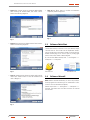
U N I N T E R R U P T I B L E P O W E R S U P P LY ( U P S ) + V O LTA G E S TA B I L I Z E R S A N D P O W E R L I N E C O N D I T I O N E R S + S W I TC H M O D E P O W E R S U P P LY + I N D U S T R I A L P O W E R S U P P LY + L I G H T I N G F LO W D I M M E R S TA B I L I Z E R S UNINTERRUPTIBLE POWER SUPPLY SPS.ONE USER UPS MANUAL USER SOFTWARE MANUAL USER’S MANUAL Page 2 Page 14 + S TAT I C I N V E R T E R S U N I N T E R R U P T I B L E P O W E R S U P P LY ( U P S ) + V O LTA G E S TA B I L I Z E R S A N D P O W E R L I N E C O N D I T I O N E R S + S W I TC H M O D E P O W E R S U P P LY + I N D U S T R I A L P O W E R S U P P LY UNINTERRUPTIBLE POWER SUPPLY SPS.ONE USER’S MANUAL + L I G H T I N G F LO W D I M M E R S TA B I L I Z E R S + S TAT I C I N V E R T E R S GENERAL INDEX. 1. INTRODUCtioN. 1.1. 1.2. 1.2.1. 1.2.2. Gratefulness letter. Using this manual. Used conventions and symbols. For more information and/or help. 2. QUALITY AND STANDARD GUARANTEE. 2.1. Management declaration. 2.2. Standard. 2.3. Environment. 3. PACKAGE CONTENTS. 4. PRODUCT OVERVIEW. 4.1. FRONT VIEW 4.2. BACK VIEW 5. installation and initial startup. 5.1. placement and storage conditions. 5.2. CONNECT TO UTILITY AND CHARGING. 5.3. connect the loads. 5.4. CONNECT MODEM / PHONE / NETWORK FOR SURGE PROTECTION. 5.5. CONNECT COMMUNICATION CABLE. 5.6. TURN ON / OFF THE UNIT. 6. IMPORTANT SAFETY WARNING. 7. SOFTWARE DOWNLOAD AND INSTALLATION. 8. Trouble Shooting. 9. specifications. SALICRU 3 1. INTRODUCtioN. 1.1. Gratefulness letter. We would like to thank you in advance for the trust you have placed in us by purchasing this product. Read this instruction manual carefully before starting up the equipment and keep it for any possible future consult that can arise. We remain at you entire disposal for any further information or any query you should wish to make. Yours sincerely. SALICRU The equipment here described can cause important physical damages due to wrong handling. This is why, the installation, maintenance and/or fixing of the here described equipment must be done by our staff or specifically authorised. According to our policy of constant evolution, we reserve the right to modify the specifications in part or in whole without forewarning. All reproduction or third party concession of this manual is prohibited without the previous written authorization of our firm. 1.2. Using this manual. The target of this manual is to give explanations and procedures for the installation and operating of the equipment. This manual has to be read carefully before installing and operating it. Keep this manual for future consults. 1.2.1. Used conventions and symbols. «Warning» symbol. Carefully read the indicated paragraph and take the stated prevention measures. «Danger of electrical discharge» symbol. Pay special attention to it, both in the indication on the equipment and in the paragraph referred to this user’s manual. «Main protective earthing terminal» symbol. Connect the earth cable coming from the installation to this terminal. «Notes of information» symbol. Additional topics that complement the basic procedures. Preservation of the environment: The presence of this symbol in the product or in their associated documentation states that, when its useful life is expired, it will not be disposed together with the domestic residuals. In order to avoid possible damages to the environment, separate this product from other residuals and recycle it suitably. The users can contact with their provider or with the pertinent local authorities to be informed on how and where they can take the product to be recycled and/or disposed correctly. 1.2.2. For more information and/or help. For more information and/or help of the version of your specific unit, request it to our Service and Technical Support (S.T.S.). 4 USER MANUAL 2. QUALITY AND STANDARD GUARANTEE. 2.1. 2.2. The SPS.ONE product is designed, manufactured and commercialized in accordance with the standard EN ISO 9001 of Quality Assurance. The marking shows the conformity to the EEC Directive (quoted between brackets) by means of the application of the following standards: Management declaration. Our target is the client’s satisfaction, therefore this Management has decided to establish a Quality and Environmental policy, by means of installation a Quality and Environmental Management System that becomes us capable to comply the requirements demanded by the standard ISO 9001:2000 and ISO 14001:2004 and by our Clients and concerned parts too. Likewise, the enterprise Management is committed with the development and improvement of the Quality and Environmental Management System, through: • The communication to all the company about the importance of satisfaction both in the client’s requirements and in the legal and regulations • The Quality and Environmental Policy diffusion and the fixation of the Quality and Environment targets. • To carry out revisions by the Management. • To provide the needed resources. Management agent. The Management has designated as management agent the person in charge about the Quality and Environment department, who with independence of other responsibilities, has the responsibility and authority to assure that the processes of the quality and environmental management system are established and maintained; to inform to the Management about the operating of the quality and environmental management system, including the necessities for the improvement; and to promote the knowledge of the client’s requirements and environmental requirements at all the levels of the organization In the next PROCESS MAP is represented the interaction among all the processes of the Quality and Environmental System: CONTINUOUS IMPROVEMENT PROCEDURE / MANAGEMENT REVISION QUALITY MANAGEMENT PROCESS ENVIRONMENT MANAGEMENT PROCESS R & D PROCESS TECHNICAL OFFICE PROCESS COMMERCIAL PROCESS PRODUCTION PROCESS INTERNAL LOGISTICS PROCESS MAINTENANCE PROCESS TRAINING PROCESS Fig. 1. • 2006/95/EC of Safety of Low Voltage • 2004/108/EC of Electromagnetic Compatibility (EMC). in accordance with the specifications of the harmonized standards. Standards of reference: • EN 60950-1: Equipment Information Technology. Security. Part 1: General requirements. • IEC/EN 62040-2: Uninterruptible power supplies (UPS). Part 2: Requirements for Electromagnetic Compatibility (EMC). • IEC/EN 62040-3: Uninterruptible power supplies (UPS). Part 3: Methods of operation and specification of test requirements. When a SPS.ONE card is used as part or component of a complex system or installation, the Generic or Product standards of that installation or specific system must be applied. It is possible that when adding parts, or being under the requirements of a specific standard, all the parts have to be under corrections to assure the conformity with the European Directives and the corresponding national regulations. It is responsibility of the project Manager and/or fitter, the compliance of the standard, providing to the installation all the needed parts to comply the standard. Furthermore, the interference phenomena due to input harmonic currents exists, and although it is not regulated by these standards, it is necessary to correct in some installations. The device is a class C1 product of electromagnetic interference IEC62310-2. Depending on the installation conditions of SPS.ONE, the corrections described in the Electromagnetic Compatibility have or do not have to be done. Regarding the Safety (standard EN 60950-1), for all the versions , should be kept in mind the aspects of the Product detailed in the INSTALLATION section. 2.3. CLIENT: - PRODUCT - SERVICE CLIENTS Standard. Environment. This product has been designed to respect the environment and has been manufactured in accordance with the standard ISO 14001. Recycling the device at the end of its useful life: Our company commits to use the services of authorised societies and according to the regulations, in order to treat the recovered product at the end of its useful life (contact your distributor). Packing: To recycle the packing, follow the legal regulations in force Process map of Quality and environmental system SALICRU 5 3. PACKAGE CONTENTS. You should have received the following items inside of package: • UPS unit. 5. installation and initial startup. NOTE: Before installation, inspect the unit. Be sure that nothing inside the package is damaged. • User manual. 5.1. placement and storage conditions. • Communication cable. • Monitoring software. 4. PRODUCT OVERVIEW. 4.1. Install the UPS in a protected area that is free of excessive dust and has adequate air flow. Place the UPS away from other units at least 20 cm to avoid interference. Do NOT operate the UPS where the temperature and humidity is outside the specific limits. (Check the specs for the limitations) FRONT VIEW 5.2. Power switch Battery mode indicator: yellow AC mode indicator: green Fault mode indicator: red 4.2. BACK VIEW Output receptacles AC input Circuit breaker Modem/phone line USB Communication port CONNECT TO UTILITY AND CHARGING. Plug in the AC input cord to the wall outlet. For the best results, suggest to charge the battery at least 4 hours before initial use. The unit charges its battery while connecting to the utility. 4 hours 5.3. connect the loads. Plug in the loads to output receptacles on the rear panel of the UPS. Simply turn on the power switch of UPS unit, then devices connected to the UPS will be protected by UPS unit. CAUTION: NEVER connect a laser printer or scanner to the UPS unit. This may cause the damage of the unit.ión protección línea teléfonica / módem. 5.4. CONNECT MODEM / PHONE / NETWORK FOR SURGE PROTECTION. Connect a single modem/phone line into surge-protected “IN” outled on the back panel of the UPS unit. Connect from “OUT” outlet to the computer with another line cable. 6 USER MANUAL 5.5. CONNECT COMMUNICATION CABLE. To allow for unattended UPS shutdown/start-up and status monitoring, connect the communication cable one end to the USB port and the other to the communication port of your PC. With the monitoring software installed, you can schedule UPS shutdown/start-up and monitor UPS status through PC. 5.6. TURN ON / OFF THE UNIT. Turn on the UPS unit by pressing the power switch . Turn off the UPS unit by pressing again the power switch. SALICRU 6. IMPORTANT SAFETY WARNING. SAVE THESE INSTRUCTIONS CAUTION! To prevent the risk of fire or electric shock, install in a temperature and humidity controlled indoor area free of conductive contaminants. (See the specifications for the acceptable temperature and humidity range.) CAUTION! To reduce the risk of overheating the UPS, do not cover the UPS’ cooling vents and avoid exposing the unit to direct sunlight or installing the unit near heat emitting appliances such as space heaters or furnaces. CAUTION! Do not attach non-computer-related items, such as medical equipment, life-support equipment, microwave ovens, or vacuum cleaners to UPS. CAUTION! Do not plug the UPS input into its own output. CAUTION! Do not allow liquids or any foreign object to enter the UPS. Do not place beverages or any other liquid-containing vessels on or near the unit. CAUTION! In the event of an emergency, press the OFF button and disconnect the power cord from the AC power supply to properly disable the UPS. CAUTION! Do not attach a power strip or surge suppressor to the UPS. CAUTION! If the UPS is with metal chassis, for safety purpose, grounding is a must during UPS installation in order to reduce leakage current below 3.5mA. Attention hazardous through electric shock. Also with disconnection of this unit from the mains, hazardous voltage still may be accessible through supply from battery. The battery supply should be therefore disconnected in the plus and minus pole at the quick connectors of the battery when maintenance or service work inside the UPS is necessary. CAUTION! Servicing of batteries should be performed or supervised by personnel knowledgeable of batteries and the required precautions. Keep unauthorized personnel away from batteries. CAUTION! When replacing the batteries, use the same number and type of batteries. CAUTION! Internal battery voltage is 12VDC. Sealed, lead-acid, 6-cell battery. CAUTION! Do not dispose of batteries in a fire. The battery may explode. Do not open or mutilate the battery or batteries. Released electrolyte is harmful to the skin and eyes.CAUTION! Unplug the UPS prior to cleaning and do not use liquid or spray detergent. CAUTION! A battery can present a risk of electric shock and high short circuit current. The following precaution should be observed before replacing batteries: 1. Remove watches, rings, or other metal objects. 2. Use tools with insulated handles. 3. Wear rubber gloves and boots. 4. Do not lay tools or metal parts on top of batteries. 5. Disconnect charging source prior to connecting or disconnecting batteries terminal. 7 7. SOFTWARE DOWNLOAD AND INSTALLATION. Follow steps below to download and install monitoring software: 1. Go to the website http://www.power-software-download.com/viewpower.html 2. Click ViewPower software icon and then choose your required OS to download the software. 3. Follow the on-screen instructions to install the software. 4. When your computer restarts, the monitoring software will appear as an orange plug icon located in the system tray, near the clock. 9. specifications. Model CAPACITY 500 700 900 500 VA / 240 W 700 VA / 360 W 900 VA / 480 W INPUT Voltage 230 VAC Voltage range 162-290 VAC OUTPUT Voltage regulation ± 10% Transfer time Typical 2-6 ms, 10 ms máx. Waveform Simulated Sine Wave BATTERY 8. Trouble Shooting. Type and number Charging time Use the table below to solve minor problems. 12 V / 4,5 Ah x 1 12 V / 7 Ah x 1 PHYSICAL Dimension (D x W x H) Problem Possible cause No LED display on Low battery. the front panel. Battery fault. The UPS is not turned on. Solutions Net weight (Kg) Charge the UPS at least 6 hours. ENVIRONMENT Replace the battery with the same type of battery. Humidity Press the power switch again to turn on the UPS. COMUNICATIONS Alarm The UPS is overload. continuously sounds when the mains is normal. Remove some loads first. Before reconnecting equipment, please verify that the load matches the UPS capability specified in the specs. When power fails, back-up time is shorten. Remove some critical load. The UPS is overload. Noise level USB/RS-232 (Opcion) 287 x 100 x 142 mm 3,55 4,25 4,9 0-90 % @ 0-40ºC, non-condensing Less than 40 dB Windows 98 SE/ME/NT 4.x/2000/2003/XP/ Vista/2008 Battery voltage is too low. Charge the UPS at least 6 hours. Battery defect. It might be Replace the battery with the due to high temperature same type of battery. operation environment, or improper operation to battery. The mains is Power cord is loose. normal but yellow LED is flashing. 8 12 V / 9 Ah x 1 4-6 hours recover to 90% capacity Reconnect the power cord properly. USER MANUAL SALICRU 9 NOT: ..................................................................................................................................................................................................... NOTES: . ............................................................................................................................................................................................... .............................................................................................................................................................................................................. .............................................................................................................................................................................................................. .............................................................................................................................................................................................................. .............................................................................................................................................................................................................. .............................................................................................................................................................................................................. .............................................................................................................................................................................................................. .............................................................................................................................................................................................................. .............................................................................................................................................................................................................. .............................................................................................................................................................................................................. .............................................................................................................................................................................................................. .............................................................................................................................................................................................................. .............................................................................................................................................................................................................. .............................................................................................................................................................................................................. .............................................................................................................................................................................................................. .............................................................................................................................................................................................................. .............................................................................................................................................................................................................. .............................................................................................................................................................................................................. .............................................................................................................................................................................................................. .............................................................................................................................................................................................................. .............................................................................................................................................................................................................. .............................................................................................................................................................................................................. .............................................................................................................................................................................................................. .............................................................................................................................................................................................................. .............................................................................................................................................................................................................. .............................................................................................................................................................................................................. .............................................................................................................................................................................................................. .............................................................................................................................................................................................................. .............................................................................................................................................................................................................. .............................................................................................................................................................................................................. .............................................................................................................................................................................................................. .............................................................................................................................................................................................................. .............................................................................................................................................................................................................. .............................................................................................................................................................................................................. .............................................................................................................................................................................................................. .............................................................................................................................................................................................................. .............................................................................................................................................................................................................. .............................................................................................................................................................................................................. .............................................................................................................................................................................................................. .............................................................................................................................................................................................................. .............................................................................................................................................................................................................. .............................................................................................................................................................................................................. .............................................................................................................................................................................................................. .............................................................................................................................................................................................................. .............................................................................................................................................................................................................. .............................................................................................................................................................................................................. .............................................................................................................................................................................................................. .............................................................................................................................................................................................................. .............................................................................................................................................................................................................. .............................................................................................................................................................................................................. .............................................................................................................................................................................................................. .............................................................................................................................................................................................................. .............................................................................................................................................................................................................. .............................................................................................................................................................................................................. .............................................................................................................................................................................................................. .............................................................................................................................................................................................................. .............................................................................................................................................................................................................. .............................................................................................................................................................................................................. .............................................................................................................................................................................................................. 10 USER MANUAL + V O LTA G E S TA B I L I Z E R S A N D P O W E R L I N E C O N D I T I O N E R S + S W I TC H M O D E P O W E R S U P P LY + I N D U S T R I A L P O W E R S U P P LY + L I G H T I N G F LO W D I M M E R S TA B I L I Z E R S + S TAT I C I N V E R T E R S Avda. de la Serra, 100 08460 Palautordera BARCELONA Tel. +34 93 848 24 00 902 48 24 00 Fax. +34 94 848 11 51 [email protected] Tel. (S.T.S.) 902 48 24 01 Fax. (S.T.S.) +34 848 22 05 [email protected] SALICRU.COM BRANCHES AND SERVICES and TECHNICAL SUPPORT (S.T.S.....) MADRID PALMA DE MALLORCA BARCELONA PAMPLONA BADAJOZ SAN SEBASTIAN BILBAO SANTA CRUZ DE TENERIFE GIJÓN SEVILLA LA CORUÑA VALENCIA LAS PALMAS DE G. CANARIA VALLADOLID MÁLAGA ZARAGOZA MURCIA SUBSIDIARIES FRANCIA RUSIA PORTUGAL CHINA HUNGRIA SINGAPUR REINO UNIDO MÉXICO POLONIA URUGUAY REST of WORLD ALEMANIA ECUADOR BÉLGICA PERÚ DINAMARCA ARABIA SAUDÍ GRECIA ARGELIA HOLANDA EGIPTO IRLANDA JORDANIA NORUEGA KUWAIT REPÚBLICA CHECA MARRUECOS SUECIA TÚNEZ SUIZA KAZAJSTÁN UCRANIA PAKISTÁN ARGENTINA FILIPINAS BRASIL INDONESIA CHILE MALASIA COLOMBIA TAILANDIA Product Range Uninterruptible Power Supply UPS Voltage Stabilizers and Power Line Conditioners Switch Mode Power Supplies Industrial Power Supplies Lighting Flow Dimmer-Stabilizers Static Inverters Continuous Regulation Autotransformers EK808A01 Nota: Salicru can give other electronics solutions according to the application specifications or technical specifications. U N I N T E R R U P T I B L E P O W E R S U P P LY ( U P S ) U N I N T E R R U P T I B L E P O W E R S U P P LY ( U P S ) + L I G H T I N G F LO W D I M M E R S TA B I L I Z E R S + P O W E R S U P P LY + S TAT I C I N V E R T E R S + P H OTO V O LTA I C I N V E R T E R S + M I C R OT U R B I N E S + V O LTA G E S TA B I L I S E R S MANAGEMENT SOFTWARE FOR UNINTERRUPTIBLE POWER SUPPLY SYSTEMS ViewPower USER MANUAL, VER.2.02 GENERAL INDEX General index 1. ViewPower Overview 1.1 1.2 1.3 1.4 Introduction Structure Applications Features 2. ViewPower Install, Quick Start, and Uninstall 2.1 2.2 2.3 2.4 System Requirement Software Install Software Quick Start Software Uninstall 3. ViewPower GUI Interface 3.1 3.2 3.3 3.3.1 3.3.2 Refresh UPS Searching UPS Navigation Monitored UPS Information UPS Remote Control & Monitor 4. ViewPower Function Menu 4.1 ViewPower Configuration 4.1.1 Password Configuration 4.1.2 SMS Configuration 4.1.3 E-mail Configuration 4.1.4. Event Action Configuration 4.1.5 Wake on LAN 4.2 UPS Setting 4.2.1 Local Shutdown 4.2.2 Remote Shutdown 4.2.3 Parameter Setting 4.2.4 Purchasing Information 4.3 Control 4.3.1 Real-time Control 4.3.2 Scheduled On/Off 4.3.3 Scheduled Battery Self-Test 4.4 View 4.4.1 Status 4.4.2 History 4.5 Format. 4.6. Language 4.7 Help. Appendix A: Glossary SALICRU 3 VIEWPOWER OVERVIEW 1. ViewPower Overview 1.1 Introduction ViewPower is UPS management software which is perfect for home users and enterprises. It can monitor and mange from one to multiple UPSs in a networked environment, either LAN or INTERNET. It can not only prevent data loss from power outage and safely shutdown systems, but also store programming data and scheduled shutdown UPSs. 1.2 Structure 1.4 Features • Allows control and monitoring of multiple UPSs via LAN and INTERNET. • Real-time dynamic graphs of UPS data (voltage, frequency, load level, battery capacity). • Safely OS shutdown and protection from data loss during power failure. • Warning notifications via audible alarm, pop-up screen, broadcast, mobile messenger, and e-mail. • Scheduled UPS on/off, battery test, programmable outlet control, and audible alarm control. • Password security protection and remote access management. ViewPower includes ViewPower service, GUI (user interface) and ViewPower icon. ViewPower service is the core of ViewPower software. It’s a system program running in the back end. It will communicate with UPS, record event, notify users with events, and execute command according to users’ request. GUI is operated in IE and communicated with back-end program. Users can monitor UPSs for real-time status, information and modify UPS setting parameters via GUI. ViewPower icon is managing tool for ViewPower software. When ViewPower is activated, there is an orange plug icon located in taskbar. It also will display pop-up dialog for current UPS status. NOTE: Tray icon only exists under Windows OS. 1.3 Applications • Monitor and manage the local UPS connected to local computer. • Monitor and manage other UPSs (with ViewPower software installed) in LAN. • Remote monitor and manage other UPSs via INTERNET from remote PC (with ViewPower software installed). 4 USER MANUAL 2. ViewPower Install, Quick Start, and Uninstall VIEWPOWER INSTALL, QUICK START, AND UNINSTALL • Step 2 PC will show the following screen as Diagram 2-2. Then Click “install” button to start the installation. 2.1 System Requirement • 128 MB physical memory at least (256 MB is recommended) • 160MB hard disk space at least • Administrator authority is required • More than 16-bit colours and 800 x 600 or above resolution display is recommended • TCP/IP protocol must be installed for network management • An available communication port (RS232 serial port or USB port) is needed • Platforms supported by ViewPower are listed below: W indows 98 Windows 2000 Windows 2003 Windows XP Windows VISTA Windows 2008 Windows 7 RedHat Linux 8 and above RedHat Enterprise AS3 and above Suse Linux 10 and above Ubuntu 6.10 and above Fedora 5 and above MacOSX 10.3, 10.4, 10.5 Solaris 10 Fig. 2. • Step 3 After clicking install, it will display the installation in process. Refer to the diagram 3. Fig. 3. • Step 4 Click “Next” button to enter the pre-installation process. Refer to the following diagram 4. 2.2 Software Install • Step 1 Insert the ViewPower CD into CD ROM. ViewPower will display the installation menu, or you can run autorun. exe to start the installation in CD directory. Refer to the diagram 1: Fig. 4. Fig. 1. SALICRU 5 VIEWPOWER INSTALL, QUICK START, AND UNINSTALL • Step 5 Click “Choose” button to change the default folder. After choosing the installed folder, click “Next” button. Refer to the following diagram 5. Fig. 5. • Step 6 Choose the shortcut folder and click “Next” button. Refer to the following diagram 6. • Step 8 Click “Done” button to confirm the installation completely. Refer to Diagram 8. Fig. 8. 2.3 Software Quick Start The Installer will leave a shortcut icon on your desktop. Simply click the shortcut. Then it will start the ViewPower and display an orange plug icon located in taskbar. To launch the GUI, double click the plug icon or choose “open” by clicking right button of the mouse. Refer to below diagram. Or, use the Start Menu method; Start >> All Programs >> Viewpower >> Viewpower Fig. 6. • Step 7 It will display the software summary before installation. Click “Install” button to start the installation and refer to Diagram 7. Shortcut icon ViewPower icon 2.4 Software Uninstall Note: Before uninstall ViewPower, you must stop all ViewPower programs first and then log in as “Administrator”! Otherwise it can’t be uninstalled completely. Please choose Start >> All Programs >> Viewpower >> Uninstall. Then follow the on-screen instruction to uninstall the software. Fig. 7. 6 USER MANUAL 3. ViewPower GUI Interface VIEWPOWER GUI INTERFACE 3.1 Refresh Click the Refresh icon gram 10). to refresh screen (Refer to Dia- The GUI has five sections as marked in the illustration below: Fig. 10. Fig. 9. A. Function Menu offers complete tool-set for navigating and setting the GUI. 3.2 UPS Searching B. Shortcut Menu provides short cuts to more commonly used functions. • Step 1 Click the UPS Searching icon to search UPS devices in LAN or INTERNET. • Step 2 Click the UPS search icon (Refer to Diagram 11). C. Current Monitoring Information displays user ID and monitored UPS name. D. UPS Navigation indicates all UPS locations in networked environment. E. Main Window contains information and/or controls that change with each function menu or shortcut menu selected. Note: This software can be used for Online and Off-line UPSs. Some functions may not be applied in Off-line UPS. Then the main window will display in grey colour. Besides, some functions are available for Administrator only to operate. Unauthorized users are not allowed to operate and the main window will display in grey colour, too. Fig. 11. • Step 3 Select LAN band for LAN search or enter IP address for INTERNET search. • Step 4 Click “search” button and the system will start search UPSs. All UPSs found in LAN or INTERNET will be listed in UPS Navigation section. SALICRU 7 VIEWPOWER GUI INTERFACE 3.3 UPS Navigation 3.3.2 UPS Remote Control & Monitor It displays all UPSs found through UPS searching function. If you want to control and set up the remote UPS, you must log in as an administrator. There are two ways to remote monitor UPS: CURRENT means currently connected PC and UPS device. LAN means connected PCs and UPS devices in local area network. INTERNET means connected PCs and UPS devices in wide area network. • Method 1: Double click any UPS from UPS navigation and it will pop up a message window to confirm the monitoring action. Refer to below diagram. NOTE: The definition of LAN and INTERNET depends on the local PC location. 3.3.1 Monitored UPS Information Select one UPS from UPS navigation and it will display complete UPS information in main window. Refer to Diagram 12. • UPS rated information includes rated VA, rated output voltage, rated output frequency, rated output current, and rated battery voltage. • Battery information includes battery group numbers. • Purchasing information means UPS purchasing date, battery purchasing date, warranty for UPS, and warranty for battery. Fig. 12. Fig. 13. Select “Yes” and it will open another new window to display remote UPS information. Refer to Diagram 14. Fig. 14. • Method 2: Open IE and enter the remote UPS IP address and 15178. For example, remote UPS ID address is 202.16.53.142. Please enter http://202.16.53.142:15178 ein IE. Refer to Diagram 15. Fig. 15. 8 USER MANUAL 4. ViewPower Function Menu VIEWPOWER FUNCTION MENU • Step 1 Choose ViewPower Configuration >> SMS. Refer to Diagram 17. 4.1 ViewPower Configuration 4.1.1 Password Configuration It’s password configuration for administrator only. Before operating and configuring the software, please login first and modify the password. The default password is “administrator” at first log in. Users can only browse UPS status and information as Guest status without login as an Administrator. Guest can NOT control or executive any setting. Modify password • Step 1 Select ViewPower Configuration>>Password. Refer to Diagram 16. Fig. 17. • Step 2 Select communication port and baud rate. • Step 3 Enter mobile phone numbers in “Phone no.” column and click “Add” button to add phone no. in Receivers List. To delete numbers, simply select phone no. from “Receivers list” and click “Delete”. • Step 4 Click “Apply” button to save all changes. The “Test” button can be used to send test SMS to confirm the correct operation. If all parameters are set up correctly, system will send a test message to all receivers and pop up a successful message. (Refer to Diagram 18) Otherwise, it will pop up a failure dialog to indicate there is an error for parameter setting. (Refer to Diagram 19). Fig. 16. • Step 2 Enter old password, new password, and retype new password in confirm password column to modify password for administrator. (The password should be at least 6 digits) Then click “Apply” button to successfully modify password for administrator. NOTE: Simply click “Login” button on the top right corner to log in the software. Fig. 18. 4.1.2 SMS Configuration It’s for entering SMS receiver list. In the event of an alarm condition occurring, a message about UPS status will be sent to the specified users via mobile phone. For the event receiving list, please configure in “Event Action” column (refer to section 4.1.4). Fig. 19. SALICRU 9 VIEWPOWER FUNCTION MENU 4.1.3 E-mail Configuration This feature enables the configuration to send alarm mail by SMTP server. For the event receiving list, please configure in “Event Action” column (refer to section 4-1-4). To use this function, the e-mail service must be correct configured on the computer. All values in this function page are default empty. This action can’t be executed without the SMTP information, e-mail account, and password. Besides, the sender account should be allowed for SMTP/POP3 forwarding. 4. Broadcast: It will send the event message to all PCs with ViewPower installed in LAN network. 5. SMS: It will send the event message to specific mobile phone numbers after events occur. 6. E-mail: It will send the event e-mail to assigned e-mail accounts after events occur • Step 1 Select ViewPower Configuration >> Event Actions. Refer to Diagram 21. • Step 1 Select ViewPower Configuration >> E-mail. Refer to Diagram 20. Fig. 21. Fig. 20. • Step 2 Enter SMTP IP, user ID, and password. Click checkbox of password authentication needed for password verify. • Step 3 Enter correct e-mail accounts in E-mail column. Then click “Add” to add into receivers list. To delete e-mail account, simply select accounts from Receivers list and click “Delete” button. • Step 4 Click “Apply” to save all changes. The “Test” button can be used to send a test e-mail to all receivers to confirm correct operation. When the test e-mails are successfully sent to specific recipients, it will pop up a successful message on operated PC. Otherwise, it will pop up a failure dialog to indicate there is an error for parameter setting. • Step 2 Select a specific event from “Event List” and then action method page will be active on the right-hand column. • Step 3 Select desired action methods by clicking checkbox. • Step 4 Click “Apply” button to save all configurations. NOTE1: When editing receiver list in SMS or e-mail columns, it’s necessary to refresh the event action page to reload the updated receiver list. NOTE2: It is requested to have following conditions for successful broadcast. 1. All receiving PCs must have installed ViewPower software. 2. Only send the message to the PCs in LAN found in UPS Navigation. 4.1.4. Event Action Configuration It’s to configure response actions for UPS events. ViewPower provides six response actions after events occur. 1. Event record: It will record event to data log in ViewPower software after events occur. This function is default selected. 2. Computer alarm: Computer will beep to remind users after events occur. This function is only available for Windows OS. 3. Warning dialog (local): It will pop up a message dialog around the ViewPower orange plug icon in taskbar after events occur. This function is default selected. 10 USER MANUAL 4.1.5 Wake on LAN It will manage the list for wake on LAN and test the function. After adding MAC address of remote PCs into MAC list, it will allow remote control the PCs. However, it’s also required to have hardware support for remote PCs to implement this function. • Step 1 Select ViewPower Configuration >> Wake on LAN. Refer to Diagram 22. Fig. 22. • Step 2 Add: Enter MAC address and click “Add” button to add in MAC List. Delete: Select one from list and click “Delete” button. Test: Select one from list and click “Test” button. Then it will execute Wake-on-LAN test. NOTE: The MAC address format example: 01-1F-C6-C7E0-08. 4.2 UPS Setting 4.2.1 Local Shutdown It’s shutdown setting for local PC which is directly connected to monitored UPS with communication port. This configuration enables system shutdown of local PC or to remote shut down PCs which are powered by monitored UPS. • Step 1 Select UPS Setting >> Local Shutdown or click shortcut icon. Refer to Diagram 23. Fig. 23. SALICRU VIEWPOWER FUNCTION MENU • Step 2 Select shutdown conditions and power-off options, set delay time to shutdown system. • Step 3 Enter time for pop-up dialog before shutdown and warning interval in Warning Dialog Setting area. • Step 4 Click “Apply” button to save all data. NOTE: Click “Default” button to recover the default setting. Conditions: UPS works on battery mode Local system shutdown after xx min xx sec: When clicking the checkbox, local PC will start to shut down after monitored UPS works on battery mode for xx min xx sec time. The maximum setting number for minutes is 999, and for seconds is 59. Local system shutdown when UPS is at low battery level: When clicking this checkbox, local PC will shut down when monitored UPS is at low battery level. Allows local system shutdown when UPS is scheduled off: When clicking this checkbox, the local system will shut down before monitored UPS is scheduled to power off. The default setting is clicked. Accept shutdown command from remote system: When clicking the checkbox, it accepts shutdown command from specific remote PCs. Please enter IP address of remote systems in blank column and click “Add” button to add into list. UPS shutdown while system shutdown: When click the checkbox, monitored UPS will shut down after local system shuts down. The UPS shutdown time will be later than system complete shutdown time. The default setting is clicked. But users can choose to shut down the system without shutting down the monitored UPS. Power-off option: Selecting power-off method for above shutdown system. Shutdown: When clicking the checkbox, the selected system will shut down. The default setting is clicked. Sleep mode: When clicking the checkbox, selected system will suspend the system instead of a normal shutdown. But this function is only supported by Windows 2000 or higher on supported hardware. Delay time to shutdown system: Enter the delay time to shut down the operating system. The value range is from 1 to 99 minutes. On shutdown execute file: Enter the path of executed file. Warning Dialog Setting: Pop-up dialog before shutdown: Timer setting for popup warning dialog displayed in local PC. Local PC will pop up a warning dialog before system starts to shut down. The range is from 1 to 999 seconds. Warning dialog interval: Reminding dialog interval setting. This setting also applies for UPS shutdown because of power failure. The range is from 1 to 999 seconds. 11 VIEWPOWER FUNCTION MENU 4.2.2 Remote Shutdown 4.2.3 Parameter Setting This configuration is to remote shut down specific PCs which are powered by monitored UPS. Some UPS functions can be set and changed via software. Parameter setting includes backup time setting for P1, battery number setting, voltage and frequency range setting for bypass mode, and voltage range setting for ECO mode. • Step 1 Select UPS Setting >> Remote Shutdown. Refer to Diagram 24. • Step 1 Select UPS Setting >> Parameter Setting. Refer to Diagram 25. Fig. 24. • Step 2 Select remote shutdown conditions. • Step 3 Add/Delete remote system IP address. • Step 4 Click “Apply” button to save all data. NOTE: Click “Default” button to recover the default setting. Conditions: UPS works on battery mode Remote systems shutdown after xx min xx sec: When clicking the checkbox, remote systems which are powered by monitored UPS will shut down after monitored UPS running on battery mode for xx min xx sec. The maximum setting number for minutes is 999, and for seconds is 59. Remote systems shutdown when UPS is at low battery level: When clicking the checkbox, remote systems which are powered by monitored UPS will shut down when monitored UPS is at low battery level. 12 Fig. 25. • Step 2 Select the functions by clicking “Enable” or “Disable” button. Or change the numbers by clicking up-down arrows or modify the numbers directly in the number column. • Step 3 Click “Apply” button to save the settings. Each function setting is saved by clicking each “Apply” button. NOTE 1: Any functions which are not supported by UPS will not be able to access. NOTE 2: Click “Default” button to recover the default setting. Alarm at bypass mode: If enabled, UPS alarms when it’s working at bypass mode. Vice versa. Alarm at battery mode: If disabled, UPS will not alarm when it’s working at battery mode. Vice versa. Auto reboot: If enabled, UPS will auto recover when AC is recovering. Vice versa. Bypass when UPS is off: If enabled, AC will directly provide power to connected devices when UPS is off. Vice versa. Converter mode: If enabled, the UPS will operate in converter mode. Vice versa. ECO mode: If enabled, the UPS will operate in ECO mode when input voltage is within acceptable range. Vice versa. Battery open status check: If enabled, the monitored UPS will check if the battery connection ok or not when UPS is turned on. Cold start: If disabled, the UPS can be turned on only when AC is normally connected to UPS. Vice versa. Bypass not allowed: If enabled, the UPS will not transfer to bypass mode under any conditions. If disabled, the UPS will be allowed to transfer to bypass mode according to UPS internal setting. USER MANUAL Battery deep-discharge protection: If enabled, the monitored UPS shutdown in accordance with the condition of battery and load on battery mode to protect battery. Vice versa. Site fault detection: If enabled, the monitored UPS will beep when the input neutral and hot wires are reversed. Vice versa. P1 Programmable outlet control (battery mode): If enabled, when UPS is running at battery mode, it will cut off P1 outlets after backup setting time arrive. If disabled, UPS will provide continuous power to P1 outlets until the battery is running out. Outlet setting: Users can set limited backup time for P1 outlets when UPS is on battery mode. Battery numbers setting: Numbers in parallel: set battery numbers in parallel. Voltage and frequency range for bypass mode: Set acceptable voltage and frequency range in bypass mode. Maximum and minimum voltage: When UPS is on bypass mode and input voltage is out of setting range, UPS will enter battery mode. Maximum and minimum frequency: When UPS is on bypass mode and input frequency is out of setting range, UPS will enter battery mode. Voltage range for ECO mode: Set acceptable voltage range for ECO mode. 4.2.4 Purchasing Information Users can enter UPS purchasing date, battery purchasing date, UPS warranty time, and battery warranty time. • Step 1 Select UPS Setting >> Purchasing Information. Refer to Diagram 26. VIEWPOWER FUNCTION MENU 4.3 Control 4.3.1 Real-time Control • Step 1 Select Control >> Real-time Control or click shortcut icon . Refer to Diagram 27. Fig. 27. • Step 2 Choose real-time control function by clicking “Start” button on each function section. You can real-time control the UPS by executing following operation: UPS turn On/Off: Click “On” to turn on the UPS and “Off” to turn off the UPS immediately. Alarm Control: Click “On” to turn on alarm system and “Off” to turn off alarm system immediately. Battery Self-Test: ViewPower offers three types of battery self-test: 10-second self-test, deep discharge test, and self-defined self-test. Simply clicking “Start” button from each type. It will execute the self-test immediately. Outlet Control: It will cut off P1 outlets when setting time arrives. When entering 0 in timer column and click “Start” button, it will cut off outlets immediately when UPS works in battery mode. Fig. 26. • Step 2 Enter data in the screen. • Step 3 Click “Apply” button to save all data. SALICRU 13 VIEWPOWER FUNCTION MENU 4.3.2 Scheduled On/Off 4.3.3 Scheduled Battery Self-Test Scheduled UPS on/off can be executed once, daily, weekly. In the window “Scheduled On/Off Setting”, users can choose time parameters. It is recommended to set only one action in the same time. If multiple actions have been specified at the same time, some of these actions may be ignored. Any actions which are not supported by the UPS will be ignored. Scheduled battery self-test can be executed once, daily, weekly, or monthly. In the window of “Scheduled Battery SelfTest Setting”, users can choose time parameters. It is recommended to set only one action in the same time. If multiple actions have been specified at the same time, some of these actions may be ignored. Any actions which are not supported by the UPS will be ignored. • Step 1 Select “Control” >> Scheduled On/Off. Refer to Diagram 28. Fig. 28. • Step 2 Set frequency and setting time on the right column. NOTE: Rules for setting time. Daily schedule – Power-off time should be earlier than power-on time. It only applies to set power-on time and power-off time within the same day. Weekly schedule – Power-off time should be earlier than power-on time. It only applies to set power-on time and power-off time within the same week. • Step 3 Click “Add” to add task. If task is successfully set, it will display on the task table on the left-hand side. Select specific task and click “Delete” button to delete the task. 14 • Step 1 Select Control >> Battery Self-Test. Refer to Diagram 29. Fig. 29. • Step 2 Select method and time parameters. There are three self-test methods: 10-second self-test: Battery will discharge for 10 seconds. Self-test: Users can set battery discharge time for self-test. Deep test: This test will let battery discharge until it’s in low battery level. • Step 3 Click “Add” to add task. If task is successfully set, it will display on the task table on the left-hand side. Select specific task and click “Delete” button to delete the task. USER MANUAL VIEWPOWER FUNCTION MENU 4.4 View 4.4.1.3 Diagram 4.4.1 Status In the Diagram window, it’s shown real-time monitored UPS data including voltage, frequency, load, battery, temperature information in diagram. 4.4.1.1 Power Flow • Step 1 Select View >> Status >> Diagram. Refer to Diagram 32. In the Power Flow window, it’s shown the internal dynamic working scheme of the UPS. Green/black flow means OK and working. Grey bar means that the object is present but not in use at the moment. There are four information blocks to display details for input, output, UPS and battery information. • Input information includes input voltage and input frequency. • Output information includes output voltage, output frequency, load level, and output current. • UPS information includes UPS mode, UPS temperature. • Battery information includes battery voltage and battery capacity. Select View >> Status >> Power Flow or click shortcut icon. Refer to Diagram 30. Fig. 30. 4.4.1.2 UPS Info Select View >> Status >> UPS Info. Refer to Diagram 31. Fig. 32. • Step 2 Select monitoring parameters on left-hand tab to switch diagram. Input voltage monitoring shows any change for input voltage. Output voltage monitoring shows any change for output voltage. Input frequency monitoring shows any change for input frequency Output frequency monitoring shows any change for output frequency. Load level monitoring shows any change for connected load level Battery capacity monitoring shows any change for connected battery capacity. UPS temp. monitoring shows any temperature change for monitored UPS. • Step 3 Time interval setting, It displays real-time data changes in certain interval. To change time interval in Xaxis of diagram, simply click up-down arrows and then click “Refresh” icon to get the updated diagram with new setting interval. Refer to Diagram 32. Fig. 31. In the UPS Info window, it’s shown detailed UPS real-time information. SALICRU 15 VIEWPOWER FUNCTION MENU 4.4.2 History • Step 1 Select View >> History >> Event Statistics. Or click shortcut icon. Refer to Diagram 34. 4.4.2.1 Event Log In the Event Log window, it’s shown all history events. Users can analyse the history data and improve the current electricity environment according to history data. • Step 1 Select View >> History >> Event Log. Refer to Diagram 33. Fig. 34. Fig. 33. • Step 2 Select UPS from com. port list. Users still can retrieve old data saved in the software even though the UPS is no longer connected to local system. • Step 3 Select time period by clicking calendar icon. Then click “Browse” button to get list of all history events during selected period time. • Step 4 Print/Delete/Export function keys. “Print”: Click “Print” button to print the current event log. “Delete/Delete All”: To delete specific event, simply select that event and then click “Delete” button. Or click “Delete All” button to delete all history events on the listed table. “Export”: Click “Export” button to save listed table to local PC in .CSV file. 4.4.2.2Event Statistics It will list down and provide all event statistics for UPSs with ViewPower installed based on time period A and time period B, and the change percentage [= 100*(B/A – 1)%]. NOTE: Event types include UPS internal event, bypass event, battery event, software event, load event, input event, parallel system event and communication event. • Step 2 Select UPS from com. port list. Users still can retrieve old data saved in the software even though the UPS is no longer connected to local system. • Step 3 Select two periods from clicking “calendar” icon. Then click “Browse” button. The result statistics will be listed in below table according to event types. Refer to Diagram 35. Fig. 35. • Step 4 Click “Print” button to print event statistics. 4.4.2.3. Data In the window of Data, it shows UPS power data in figures during selected period time. ViewPower software also offers print, save as, and delete functions. • Step 1 Select View >> History >> Data. Refer to Diagram 36. Fig. 36. 16 USER MANUAL • Step 2 Select UPS from com. port list. Users still can retrieve old data saved in the software even though the UPS is no longer connected to local system. • Step 3 Select the starting time and ending time by clicking calendar icon. Then click “Browse” button to get the data table. “Print”: Print the listed data table. “Delete”: Select specific data and click “Delete” button to delete the record. “Delete All”: Click “Delete All” button to delete all records on the listed table. “Export”: Click “Export” button to save listed table to local PC in .CSV file. 4.4.2.4 Diagram In the Diagram window, it shows UPS power data in diagram during selected period time. UPS power data includes input voltage, output voltage, input frequency, output frequency, load level, battery capacity, and UPS temperature. • Step 1 Select View >> History >> Diagram. Refer to Diagram 37. VIEWPOWER FUNCTION MENU 4.6. Language Currently, ViewPower offers eleven languages for selection: • Chinese • English • German • Italian • Polish • Portuguese • Russian • Spanish • Ukrainian • French • Turkish When first using the software, it will search proper language to display according to OS language. 4.7 Help. • About: Click “Help” menu and select “About” item. It represents the copyright information about ViewPower. • Help: Click “Help” menu and select “Online help” item. It will open the help manual. Before operating ViewPower software, please read manual carefully. Appendix A: Glossary Fig. 37. • Step 2 Select UPS from com. port list. Users still can retrieve old data saved in the software even though the UPS is no longer connected to local system. • Step 3 Select cycle and period time. Then click “Browse” button to get the diagram. • Step 4 Select monitoring parameters on left-hand tab to switch diagram. • Local PC (system): The local PC (system) is physically connected to UPS with communication port. • Remote PCs (systems): The remote PCs (systems) are physically powered by UPS without communication port connection. 4.5 Format. Full Screen: Click “Full Screen” to get the software in full screen. Then press “ESC” key to get back to normal screen. Users can choose formats for temperature unit and date. Temperature Unit: There are two temperature units for selecting: Centigrade and Fahrenheit. Default setting is centigrade. Date Format: There are four formats for date display: YYYYMM-DD, YYYY/MM/DD, MM-DD-YYYY, MM/DD/YYYY. Default setting is YYYY-MM-DD. SALICRU 17 VIEWPOWER FUNCTION MENU NOTAS: . .............................................................................................................................................. ............................................................................................................................................................. ............................................................................................................................................................. ............................................................................................................................................................. ............................................................................................................................................................. ............................................................................................................................................................. ............................................................................................................................................................. ............................................................................................................................................................. ............................................................................................................................................................. ............................................................................................................................................................. ............................................................................................................................................................. ............................................................................................................................................................. ............................................................................................................................................................. ............................................................................................................................................................. ............................................................................................................................................................. ............................................................................................................................................................. ............................................................................................................................................................. ............................................................................................................................................................. ............................................................................................................................................................. ............................................................................................................................................................. ............................................................................................................................................................. ............................................................................................................................................................. ............................................................................................................................................................. ............................................................................................................................................................. ............................................................................................................................................................. ............................................................................................................................................................. ............................................................................................................................................................. ............................................................................................................................................................. ............................................................................................................................................................. ............................................................................................................................................................. ............................................................................................................................................................. ............................................................................................................................................................. ............................................................................................................................................................. ............................................................................................................................................................. ............................................................................................................................................................. ............................................................................................................................................................. ............................................................................................................................................................. ............................................................................................................................................................. ............................................................................................................................................................. ............................................................................................................................................................. ............................................................................................................................................................. ............................................................................................................................................................. ............................................................................................................................................................. ............................................................................................................................................................. ............................................................................................................................................................. ............................................................................................................................................................. ............................................................................................................................................................. ............................................................................................................................................................. ............................................................................................................................................................. 18 USER MANUAL U N I N T E R R U P T I B L E P O W E R S U P P LY ( U P S ) + L I G H T I N G F LO W D I M M E R S TA B I L I Z E R S + P O W E R S U P P LY + S TAT I C I N V E R T E R S + P H OTO V O LTA I C I N V E R T E R S + M I C R OT U R B I N E S + V O LTA G E S TA B I L I S E R S Avda. de la Serra, 100 08460 Palautordera BARCELONA Tel. +34 93 848 24 00 902 48 24 00 Fax. +34 94 848 11 51 [email protected] Tel. (S.T.S.) 902 48 24 01 Fax. (S.T.S.) +34 848 22 05 [email protected] SALICRU.COM BRANCHES AND SERVICES and TECHNICAL SUPPORT (S.T.S.....) MADRID PALMA DE MALLORCA BARCELONA PAMPLONA BILBAO SAN SEBASTIAN GIJÓN SEVILLA LA CORUÑA VALENCIA LAS PALMAS DE G. CANARIA VALLADOLID MÁLAGA ZARAGOZA MURCIA SUBSIDIARIES FRANCIA CHINA PORTUGAL SINGAPUR HUNGRIA MÉXICO REINO UNIDO ALEMANIA PERÚ BÉLGICA URUGUAY DINAMARCA VENEZUELA HOLANDA ARABIA SAUDÍ IRLANDA ARGELIA NORUEGA EGIPTO POLONIA JORDANIA REPÚBLICA CHECA KUWAIT rusia MARRUECOS SUECIA TÚNEZ SUIZA KAZAJSTÁN UCRANIA PAKISTÁN ARGENTINA uea BRASIL FILIPINAS CHILE INDONESIA COLOMBIA MALASIA CUBA TAILANDIA ECUADOR VIETNAM Product Range Uninterruptible Power Supply UPS Lighting Flow Dimmer-Stabilizers Power Supplies Static Inverters Photovoltaic Inverters Microturbines Voltage Stabilisers EK898A01 Nota: Salicru can give other electronics solutions according to the application specifications or technical specifications. REST of WORLD