1
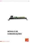
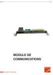
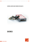
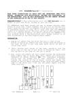
UNINTERRUPTIBLE POWER SUPPLY (UPS) + LIGHTING FLOW DIMMER STABILIZERS (ILUEST) + SWITCH MODE POWER SUPPLY + STATIC INVERTERS + PHOTOVOLTAIC INVERTERS + VOLTAGE STABILIZERS AND POWER LINE CONDITIONERS MODULE OF COMMUNICATIONS USER'S MANUAL GENERAL INDEX General index 1. Introduction. 1.1. Acknowledgement letter. 2. Information for safety. 2.1. Using this manual. 3.Presentation. 3.1. View of the Module of Communications. 3.2. Legends corresponding to the Module of Communications view. 4.Description. 4.1.Communications. 4.1.1. COM ports. 4.1.2. Relay interface. 4.1.3. Electronic unit for telemaintenance SICRES (option). 5.Application. 6.Connection. 6.1. Communication module COM. 6.1.1. Telemaintenance and RS232 and RS485 communication ports. 6.1.2. Relay interface. 6.1.3. Related to batteries (only for equipment with DC output). 6.1.3.1. Battery floating voltage/temperature compensation probe. 6.1.3.2. Electrolyte level probe (Optional). 6.1.4. Analogical and digital inputs (EMi3 and RE3 voltage stabilizers only). SALICRU 3 INTRODUCTION 1. Introduction. 1.1. Acknowledgement letter. We would like to thank you in advance for the trust you have placed in us by purchasing this product. Read this instruction manual carefully in order to be familiar with its contents, because as much you understand and know the equipment, the higher will be the satisfaction degree, safety level and functionality optimization. We remain at you entire disposal for any further information or any query you should wish to make. Yours sincerely. SALICRU T he equipment here described can cause important physical damages due to wrong handling. This is why, the installation, maintenance and/or fixing of the here described equipment must be done by our staff or specifically authorised. Although no effort has been spared to guarantee that the information in this manual is complete and accurate, we are not responsible of any errors or omissions that may exist. The images included in this document are for mere illustration and may not accurate represent the parts of the equipment showed. However, the differences that may arise will be smoothed or solved with the correct labelling on the unit. According to our policy of constant evolution, we reserve the right to modify the specifications, operating or described actions in this document without forewarning. All reproduction, copy, third party concession, modification or part or total translation of this manual or document, in any form or medium, without the previous written authorization of our firm, it is prohibited, reserving of the complete and exclusive property right over itself. 4 USER MANUAL INFORMATION FOR SAFETY 2. Information for safety. 2.1. Using this manual. The purpose of this manual or publication is to provide information regarding the safety and to give explanations about the procedures for the transport, installation and operating of the equipment. Read this manual carefully before starting or making any action on the equipment and specially in those instructions regarding safety. Keep this document for future consults and keep it on hand during the installation and commissioning procedures. In the next pages, the «(S.T.S.)» terms, is referred to the Service and Technical Support. The module of communications is part of an equipment that can be fitted in as an structured element as standard by default or as an option, being able to be partially or full installed in different equipments. As a result, read and pay attention to any Information relating to Safety stated in the user’s manual of the product that includes it or it is foreseen to have this Module of Communications. SALICRU 5 PRESENTATION 3. Presentation. 3.1. View of the Module of Communications. COM1COM2 Communication module version, for EMi3 and RE3 stabilizers. A B + –GND Common NC NO Connect Connect electrolyte temperature probe level probe COM3RELAYS 3.2. Legends corresponding to the Module of Communications view. (COM2) DB9 connector for RS232 communication port. Mutually exclusive with COM3. (COM3) Connector of three pins for RS485 communication port. Mutually exclusive with COM2. OTHERS INPUTS Connector for the electrolyte level probe option. The probe is entered in one of the batteries as a sampling mode. The circuit will be closed meanwhile the liquid is in contact with the probe and it is opened as soon as the level decreases. (COM1)Group: A Slot as standard, for SICRES communication option. B DB9 connector for RS232 communication port. In case of including the SICRES option this RS232 port is disabled. BATTERY Analog Digital input input Therefore, the probe will always be installed and linked to the battery set, either if they are fitted in the same rectifier cabinet or separate cabinet. Inputs for AC output voltage: (Analogical) In the EMI3 series stabilizer, the analogical input will be an external control input. (Digital) For the same equipment, the digital input is foreseen for an external alarm input. (RELAYS) Switch contact from nine alarm relays, given through three pins (Common, NC and NO). For equipments with DC output voltage. Both connectors relating to batteries are useful for DC equipments only. (BATTERY)By means of two separate connectors, two parameters related to batteries are managed: Connector for temperature probe (R103). Temperature probe is located in the opposite end of the bundle connected to the own connector and it allows its extension until inside the battery cabinet. This probe makes possible the measurement of the ambient temperature and its displaying in the control panel, and also the compensation of the floating voltage according to this temperature. 6 USER MANUAL DESCRIPTION 4. Description. 4.1. Communications. 4.1.1. COM ports. There are 2 RS232 ports supplied through DB9 connectors, one of them, which is COM1, is disabled when using the telemaintenance SICRES option. Also, there is a RS485 in COM3 port, which is supplied through a 3 pins connector.. RS232 from COM2 channel and RS484 from COM3 channel are mutually exclusive and they cannot be used at the same time. 4.1.2. Relay interface. By means of a communication interface with dry contacts and digital inputs, you can interact with the environment in case of alarms from the system and/or receiving external information. To do that, it is supplied the switch contacts from nine alarm relays, given through three pins (Common, NC and NO). The preset settings from factory for each product family are stated in tables from 2 to 8. Nevertheless not all the families have either the same alarms or the extended version and even the user will not be able to modify the preset setting from factory in all of them. For DC Power-S and FAC P series equipments, the user can change the settings, under his criteria, as many time as they are needed. But for the rest of products, this setting is only possible to be done at factory, so subsequently it would be needed the S.T.S intervention. By default, Relay 9 is activated with any alarm in its extended version, for those equipments that include it. 4.1.3. Electronic unit for telemaintenance SICRES (option). The electronic unit of SICRES telemanagement allows the monitoring, analysis and technical support in real time, 24 hours per day, 7 days per week, by professionals of our firm, reducing the MTTR (mean time to repair) in case of any unexpected event. During the monitoring, it is created an event and alarm logs that allow an exhaustive analysis of the equipment, providing a valuable information of the operating trend, identifying, in this way the future potential problems. Likewise, each month is sent a detailed report of the status of the equipment to the client. SALICRU 7 APPLICATION 5. Application. The Module of Communications can be included as standard or as an option, in the families of equipments stated in chart 1, with the particular restrictions or limitations of each one. Consider that there are a basic or standard version and one extended or complete one. RE3 (equipments with LCD panel only) EMi3 DC Power-S DC Power-L FAC P series Product family (0) (1) Connection availability in the communication module Standard Extended COM1 COM1 COM2 COM2 COM3 COM3 RELAYS 1-3 RELAYS 1-9 BATTERY (temp. probe) BATTERY (temp. probe) - BATTERY (electrolyte probe) COM1 COM1 - - COM3 COM3 RELAYS 1-3 RELAYS 1-9 BATTERY (temp. probe) BATTERY (temp. probe) - BATTERY (electrolyte probe) COM1 COM1 COM2 COM2 COM3 COM3 RELAYS 1-3 RELAYS 1-9 BATTERY (temp. probe) BATTERY (temp. probe) - BATTERY (electrolyte probe) COM1 (0) COM1 - - - COM3 - RELAYS 1-9 - Analog input - Digital input Slot to SICRES only COM1 - - - COM3 - RELAYS 1-5 - - - Digital input Observations Slot to SICRES (1) See table 2 Slot to SICRES (1) See table 5 and 6 Slot to SICRES (1) See table 3 and 4 Slot to SICRES (1) See table 7 Slot to SICRES (1) See table 8 Not available in EMi3 single phase equipments with case format. It is included the slot for the SICRES telemaintenance unit in all the stated equipments, but not the own SICRES card, because it is an option. Table 1. Communication ports availability per each family. 8 USER MANUAL CONNECTION 6. Connection. 6.1. Communication module COM. • Line of communications (interface) is a very low voltage circuit of safety. To preserve its quality, it has to be installed separate from other lines that have dangerous voltages (distribution energy lines). Wires used in the relay interface must be shielded and connected to earth, by means of the corresponding rod or terminal. Consider that the maximum current and voltage that the dry contacts of the COM module interface can support, will not exceed from 5 A 250 V AC or 0.5A 145 V DC. • The communication module is designed to be always fitted in a cabinet, because it doesn’t have any protection against direct contacts. • System cabinets have holes in the base or top cover, suitable to install cable bushing cones, or cable glands or even a cable gland plate for the cable entering with the corners of the plate protected in order to avoid cuts or deterioration of the cable insulation. Do not pass the cables through any hole in the plate, which its corners are not protected, because the possible damages over them will carry current leakages. 6.1.1. Telemaintenance and RS232 and RS485 communication ports. • Any reference to the telemaintenance SICRES unit foreseen to be installed into the corresponding Slot, as an option, see user’s manual EK794*00 for any consult. • The Communication Module has two RS232 ports supplied through the DB9 connector and one RS485 through a three pin connector. First RS232 is associated to COM1, it will be disabled when the telemaintenance SICRES unit is fitted in to the corresponding Slot. The own SICRES has a DB9 for the RS232 port. Second RS232 port is associated to COM2 channel. RS485 is associated to COM3 channel. Signals of the port in the three pins connector are as follows, from left (pin 1), to right (pin 3): +, – and GND. RS232 from COM2 channel and RS485 from COM3 channel are mutually exclusive regarding their use, they cannot be used at the same time. 6.1.2. Relay interface. • The Communication Module has up to 9 programmable relays. Changeover contacts of each relay are supplied through a 3 pin connector, at the front of itself and labelled as “RELAYS” and numbered from 1 to 9 from left to right. be set once and so to only one relay too. For DC Power-S and FAC P series equipments, the user can change the settings, under his criteria, as many time as they are needed. But for the rest of products, this setting is only possible to be done at factory, so subsequently it would be needed the S.T.S intervention. The preset settings from factory for each product family are stated in tables from 2 to 8. It has to be considered regarding the protections tripping or turning off of the own equipment, they will have alarm or indication effect on condition that incorporating the corresponding auxiliary contact block in each manoeuvring part, because they are option. Nr relay Description of the relay programming 1 A1 «Urgent alarm». It groups the following signals: - End of back up time alarm - Overload alarm - High battery voltage alarm - Non-critical loads alarm - Output circuit breaker «Off» alarm - Module urgent alarm (see conditions) - High input voltage alarm - Low output voltage alarm (1 minute delayed) - High output voltage alarm - Battery circuit breaker «Off» alarm 2 A2 «Non-urgent alarm». It groups the following signals: - Low battery alarm - Over temperature alarm - Safety overload alarm - Low input voltage alarm - Non-urgent modile alarm (see conditions) 3 O1 «Observation alarm». It groups the following signals: - Discharge alarm (1 minute delayed) - Use overload alarm - Shutdown alarm - High charge current alarm 4-8 9 Free relays, to be programmed by the end-user General alarm relay (any alarm active) Conditions. To trigger the «Non-urgent module alarm», one of the following alarms has to be triggered in any module, as minimum: Module mains fault (Only when this alarm is triggered in the module and it is not triggered in the Control Module). Low battery alarm of the module. End of battery back up time alarm of the module. Overload alarm of the module. Circuit breaker alarm of the module. High heatsink temperature alarm of the module. Rectifier fault alarm of the module. Shutdown alarm of the module. Over voltage alarm of the module. PFC alarm of the module. Fan fault alarm of the module. To trigger an «Urgent alarm», is necessary to trigger a «Nonurgent alarm» in two modules, as minimum. Table 2. Dry contact interface settings for standard communications of FAC P and DC Power-S series, until week 8 of 2014. Also, the relay triggering can be shown in the LCD panel of the Control Module (DC Power-S and FAC P series) or in the LCD panel of the equipment (DC Power-L and EMi3), either as an alarm or information mode, being able to group several inputs or informations and associate them to a single relay only, in which case any alarm and individually will trigger the relay in question. It has to be considered that only one alarm can only SALICRU 9 CONNECTION Nr relay 1 2 3 4-9 (2) Description of the relay programming Nr relay It groups the following signals: - Battery in discharge - Input voltage low It groups the following signals: - Battery low - End of autonomy - Overload SYSTEM - Overtemperature battery - Overload SECURITY - Overload UTILIZATION - Remote stop - Battery voltage high - URGENT modules - NO URGENT modules - High current battery charge - Input voltage high - Output voltage low - Output voltage high - Low level electrolyte It groups the following signals: - Isolation fault + (2) - Isolation fault – (2) Unusable Floating output voltage only. Table 3. Dry contact interface settings for standard communications of FAC P and DC Power-S series, from the week 8 of 2014. Reserved for internal communications 2 It groups the following signals: - Input fault - Input undervoltage RS and/or ST and/or TR 3 It groups the following signals: - Overload rectifier - Overtemperature battery - High current battery charge - Heatsink overtemperature - Low battery voltage - Battery overvoltage - Input overvoltage RS and/or ST and/or TR - Output voltage low - Output voltage high - Low level electrolyte 4 It groups the following signals: - Isolation fault + (2) - Isolation fault – (2) 5-8 9 (2) Reserved for internal communications Table 5. Dry contact interface settings for standard communications of DC Power-L. Description of the relay programming Description of the relay programming 1 Reserved for internal communications 2 It groups the following signals: - Input fault - Input undervoltage RS and/or ST and/or TR 3 It groups the following signals as URGENT: - Overload rectifier - Heatsink overtemperature - Battery voltage low - Output voltage low - Output voltage high It groups the following signals as NO URGENT: - Overtemperature battery - Overload SECURITY - Overload UTILIZATION - Battery voltage high - NO URGENT modules - High current battery charge - Input voltage high 4 It groups the following signals as NO URGENT: - Overtemperature battery - High current battery charge - Battery overvoltage - Input overvoltage RS and/or ST and/or TR 5 - Isolation fault + (2) 6 - Isolation fault – (2) 7 - Low level electrolyte 4 - Isolation fault + (2) 8 - General alarm relay (any alarm active) 5 - Isolation fault – (2) 9 Reserved for internal communications 6 - Low level electrolyte 7 - DIGITAL INPUT 1 8 - DIGITAL INPUT 2 9 - General alarm relay (any alarm active) 1 It groups the following signals: - Battery in discharge - Input voltage low 2 It groups the following signals as URGENT: - Battery low - End of autonomy - Overload SYSTEM - Remote stop - URGENT modules - Output voltage low - Output voltage high 3 (2) Unusable Floating output voltage only. Nr relay Nr relay Description of the relay programming 1 (2) Floating output voltage only. Table 6. Dry contact interface settings for extended communications of DC Power-L. Floating output voltage only. Table 4. Dry contact interface settings for extended communications of DC Power-S. 10 USER MANUAL CONNECTION Nr relay Description of the relay programming INTERNAL 1 It groups the following signals: - Output overload relay active - Output voltage out of range (max.-min detection) INTERNAL 2 - General alarm relay (any alarm active) 1 It groups the following signals: - Single phase equipment: Input overvoltage Input voltage low - Three-phase equipment: Input overvoltage, phase R and/or S and/or T Input voltage low, phase R and/or S and/or T 2 It groups the following signals: - Single phase equipment: Output overload - Three-phase equipment: Output overload, phase R and/or S and/or T 3 It groups the following signals: - Single phase equipment: Motor failure - Three-phase equipment: Motor failure, phase R and/or S and/or T 4 It groups the following signals: - Single phase equipment: Output overvoltage - Three-phase equipment: Output overvoltage, phase R and/or S and/or T 5 It groups the following signals: - Single phase equipment: Output voltage low - Three-phase equipment: Output voltage low, phase R and/or S and/or T 6 - File system failure 7 - Maintenance request 8 - Digital input 9 - General alarm relay (any alarm active) Table 7. Dry contact interface settings for extended communications of EMi3 stabilizer. Also the EMi3 equipment has two internal relays and totally separate from the communication module, which in case of requesting them they will be programmed as table 7 states and labelled as INTERNAL 1 and 2. Nr relay The two connectors related to batteries are only useful in the DC equipments. 6.1.3.1. Battery floating voltage/temperature compensation probe. • As battery suppliers recommend, a variable floating voltage has to be supplied to the batteries according to the ambient temperature. The control of this feature is done by means of the probe (R103), connected to one of the ends of the cable bundle. • In those systems where batteries share the cabinet with the own rectifier, the probe is fitted inside from factory and clamped close to the batteries shelves and connected at its opposite end to the terminal strip labelled as . • For those equipments where batteries are fitted in a separate cabinet, the bundle with the probe (R103) is supplied and connected to the terminal strip “BATTERY” labelled as . The wound up bundle is clamped at the base of the rectifier cabinet. Cut the clamp/s that fix the bundle, take the probe out of the system cabinet. Enter the probe into the cabinet and extend it until its top part, fix it by clamps to the structure of the cabinet in order to immobilised it. When fixing the probe at the top, the area with the highest temperature supposedly, the floating voltage will be compensated according to the temperature. In those cabinets with no conduits, pass the probe through the hole between any of both side covers and battery shelves. This way, it will avoid the cable being captured, chewed or broken when extracting any of the shelves. Cabinets with conduits, remove its cover, pass the bundle inside and take it out through the most suitable slot. When finishing the corresponding works, put the conduit cover back. • In case of an equipment with batteries distributed in more than one cabinet, the probe will only be installed in one of them, preferably in that cabinet where the temperature is the highest, so they are the worst conditions. For example: The cabinet most attached to the equipment, the one most cornered to the wall, the one that due to its physical layout in its location can have less air cooling flow, etc. 1 - High input voltage or low 2 - Overload 3 - Bypass 4 - High output voltage or low 6.1.3.2. 5 - Maximum-minimum output voltage (3) • Wet/flooded batteries are supplied with the suitable electrolyte level, being this procedure strictly checked because it is essential for their lifetime. In general, this procedure is done at factory, but it can be done at site due to the client’s requirements and always with the same meticulously and professionally that it requires, and before commissioning the equipment the first time. 6-9 (3) Description of the relay programming 6.1.3. Related to batteries (only for equipment with DC output). Unusable Alarm available when the stabilizer includes the maximum-minimum output voltage option only. Table 8. Dry contact interface settings for standard communications of RE3 stabilizer. Electrolyte level probe (Optional). Nevertheless, it can happen that after some time, and due to the excessive charges and discharges, external high temperatures and other factors, the level goes down. • Although in the periodic preventive maintenance visits, the electrolyte is always controlled in all cells, it can be considered that the liquid decreasing in one equipment is similar at all batteries, not to say equal. In order to guarantee a higher and permanent control over this parameter, it can be supplied the electrolyte level option, which will have to be fitted in one of the installed batteries, regardless if they are fitted in the same cabinet of the rectifier or not. SALICRU 11 CONNECTION • Basically, when the probe enters in contact with the electrolyte, which acts as a conductor, it closes a circuit. In case the liquid level decreases,the probe will not conduct and the circuit will opened, so the alarm will be triggered in the LCD of the control panel. Connect the batteries according to the described guideline in the user’s manual of the equipment. • Systems that the rectifier and batteries share the same cabinet, it is supplied the temperature probe connected to the communication module from factory (“BATTERY” terminal strip labelled as ). The probe is supplied assembled in a cap for battery cell. Remove the cap of one of the peripheral battery blocks and replace it by the one with the probe, as it is not possible to make the setting with one battery fitted in the middle of the shelf, because the electrolyte level mark can’t be checked. For equipments that the batteries are fitted in a separate cabinet, the temperature probe is supplied disconnected, coiled and fixed to the battery cabinet base. Probe installation. • To work with batteries use protection eyeglasses and gloves, and respect the safety instructions stated in the document EK266*08. • Cabinet sharing the rectifier and batteries: Remove the screws from the mechanical lock (BL) that can be found in the battery shelf ends. Proceed to locate the batteries according to the layout stated in the supplied documentation, by respecting any warning stated in the user’s manual of the equipment as regards to fix the cabinet to a solid surface and to prohibit to pull out more than one battery shelf with the batteries already fitted in. Connect the batteries according to the described guideline in the user’s manual of the equipment. The electrolyte level probe is supplied already assembled in one of the battery cells caps. Remove the cap of one of the cells and replace it by the one with the probe. Make sure to insert the cap with the probe till the end for a correct contact with the electrolyte. Set the probe depth. The plastic cap located at the end of the rod must be 4-5 mm over the line marked as «Minimum level» of the battery case. Depending on the setting system of the probe, it will be needed to slacken the rod screw or the nut to change its depth. Connect the end of the cable with the free terminal, which belongs to the connection bundle, to the positive terminal of the battery with the probe. The other end of the bundle with the probe is connected to the terminals of the Communication Module. In case of purchasing the electrolyte level probe later, the bundle has to be connected to the “BATTERY” terminal strip labelled as and make the described actions previously. In cabinets with no conduits, pass the bundle through the hole between of the two side covers and the battery shelf. Therefore, the cable will not be captured, champed or cut when removing any battery shelf. Cabinets with conduits, remove its cover, pass the bundle inside and take it out through the most suitable slot. When finishing the corresponding works, put the conduit cover back. • Separate battery cabinets from the own equipment: Remove the screws from the mechanical lock (BL) that can be found in the battery shelf ends. Proceed to locate the batteries according to the layout stated in the supplied documentation, by respecting any warning stated in the user’s manual of the equipment as regards to fix the cabinet to a solid surface and to prohibit to pull out more than one battery shelf with the batteries already fitted in. 12 Cut the clamp or clamps that fix the level probe bundle and bring it the battery shelf stated in the battery circuit diagram. Set the probe depth. The plastic cap located at the end of the rod must be 4-5 mm over the line marked as «Minimum level» of the battery case. Depending on the setting system of the probe, it will be needed to slacken the rod screw or the nut to change its depth. Remove the cap from one the batteries, the one located in the centre of the battery block. Carefully, when removing it from the battery and refitting it in the centre of new battery, because the rod of the probe can drop electrolyte. Make sure to insert the cap with the probe till the end for a correct contact with the electrolyte. Put the removed cap of the battery into the other one. Connect the end of the cable with the free terminal, which belongs to the connection bundle, to the positive terminal of the battery with the probe. The other end of the bundle with the probe is connected to the terminals of the Communication Module. Depending if there are side covers between the cabinets or not, the terminal strip will be able to be connected to the stated terminals or it will be necessary to go out from the battery cabinet to enter into the equipment through the cable gland located in both cabinets. Passing the connection bundle. In cabinets with no conduits, pass the bundle through the hole between any of the side covers and the own structure. Therefore, the connection bundle of the probe will be protected against possible damages. Cabinets with conduits, remove its cover, pass the bundle inside and take it out through the most suitable slot. When finishing the corresponding works, put the conduit cover back. Regardless where the connection bundle is passed, mechanical tensions will be avoided over the wiring. Pass the bundle between the two implicated cabinets and connect the end with the connection cables, to the terminal strip “BATTERY” of the Communication Module and labelled as . 6.1.4. Analogical and digital inputs (EMi3 and RE3 voltage stabilizers only). The communication module for EMi3 and RE3 stabilizers has two connectors foreseen for inputs, one is analogical and the other one is digital. The analogical input is not available in the RE3, although the connector could be physically found. The analogical input is an external control input and the digital is for an external alarm. The range of both inputs will be from 0 to 10 V. USER MANUAL GENERAL INDEX SALICRU 13 CONNECTION : ..................................................................................................................................................................................................................... ................................................................................................................................................................................................................................ ................................................................................................................................................................................................................................ ................................................................................................................................................................................................................................ ................................................................................................................................................................................................................................ ................................................................................................................................................................................................................................ ................................................................................................................................................................................................................................ ................................................................................................................................................................................................................................ ................................................................................................................................................................................................................................ ................................................................................................................................................................................................................................ ................................................................................................................................................................................................................................ ................................................................................................................................................................................................................................ ................................................................................................................................................................................................................................ ................................................................................................................................................................................................................................ ................................................................................................................................................................................................................................ ................................................................................................................................................................................................................................ ................................................................................................................................................................................................................................ ................................................................................................................................................................................................................................ ................................................................................................................................................................................................................................ ................................................................................................................................................................................................................................ ................................................................................................................................................................................................................................ ................................................................................................................................................................................................................................ ................................................................................................................................................................................................................................ ................................................................................................................................................................................................................................ ................................................................................................................................................................................................................................ ................................................................................................................................................................................................................................ 14 USER MANUAL CONNECTION : ..................................................................................................................................................................................................................... ................................................................................................................................................................................................................................ ................................................................................................................................................................................................................................ ................................................................................................................................................................................................................................ ................................................................................................................................................................................................................................ ................................................................................................................................................................................................................................ ................................................................................................................................................................................................................................ ................................................................................................................................................................................................................................ ................................................................................................................................................................................................................................ ................................................................................................................................................................................................................................ ................................................................................................................................................................................................................................ ................................................................................................................................................................................................................................ ................................................................................................................................................................................................................................ ................................................................................................................................................................................................................................ ................................................................................................................................................................................................................................ ................................................................................................................................................................................................................................ ................................................................................................................................................................................................................................ ................................................................................................................................................................................................................................ ................................................................................................................................................................................................................................ ................................................................................................................................................................................................................................ ................................................................................................................................................................................................................................ ................................................................................................................................................................................................................................ ................................................................................................................................................................................................................................ ................................................................................................................................................................................................................................ ................................................................................................................................................................................................................................ ................................................................................................................................................................................................................................ SALICRU 15 UNINTERRUPTIBLE POWER SUPPLY (UPS) + LIGHTING FLOW DIMMER STABILIZERS (ILUEST) + SWITCH MODE POWER SUPPLY + STATIC INVERTERS + PHOTOVOLTAIC INVERTERS + VOLTAGE STABILIZERS AND POWER LINE CONDITIONERS Avda. de la Serra, 100 08460 Palautordera BARCELONA Tel. +34 93 848 24 00 902 48 24 00 (Only Spain) Fax. +34 94 848 11 51 [email protected] Tel. (S.T.S.) +34 93 848 24 00 902 48 24 01 (Only Spain) Fax. (S.T.S.) +34 93 848 22 05 [email protected] SALICRU.COM BRANCHES AND SERVICES AND TECHNICAL SUPPORT (S.T.S.) BARCELONA PALMA DE MALLORCA BILBAO PAMPLONA GIJÓN SAN SEBASTIÁN LA CORUÑA SEVILLA LAS PALMAS DE G. CANARIA VALENCIA MADRID VALLADOLID MÁLAGA ZARAGOZA MURCIA SUBSIDIARIES CHINA MÉXICO FRANCIA PORTUGAL HUNGRíA REINO UNIDO MARRUECOS SINGAPUR ALEMANIA JORDANIA ARABIA SAUDÍ KUWAIT ARGELIA MALASIA ARGENTINA PERÚ BÉLGICA POLONIA BRASIL REPÚBLICA CHECA CHILE RUSIA COLOMBIA SUECIA CUBA SUIZA DINAMARCA TAILANDIA ECUADOR TÚNEZ EGIPTO UEA FILIPINAS URUGUAY HOLANDA VENEZUELA INDONESIA VIETNAM IRLANDA Product Range Uninterruptible Power Supply (UPS) Lighting Flow Dimmer-Stabilizers (ILUEST) Switch Mode Power Supplies Static Inverters Photovoltaic Inverters Voltage Stabilisers and Power Line Conditioners EN030G01 Nota: Salicrú can give other electronics solutions according to the application specifications or technical specifications. REST OF WORLD