1
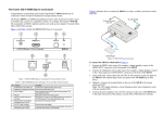
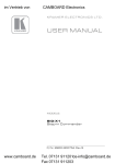
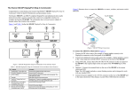
The Kramer SID-DVI DVI Step-In Commander
Figure 2 shows the wiring connections of the SID-DVI.
Congratulations on purchasing your Kramer DigiTOOLS® SID-DVI DVI Step-In
Commander which is ideal for boardrooms and presentation rooms.
The Kramer SID-DVI is a DVI and unbalanced stereo audio remote control commander
that is used to remotely take control of a compatible switcher, for example, the
VP-81SID. The commander is HDCP compliant and does not need a power adapter if
located within 50m (164ft) of the switcher.
Figure 1 and Table 1 define the SID-DVI DVI Step-In Commander.
Figure 2: SID-DVI Wiring Connections
To connect the SID-DVI as illustrated in Figure 2:
1. Connect the DVI video source (for example, a computer graphics source) to the
DVI connector on the front panel of the SID-DVI.
Figure 1: SID-DVI DVI Step-In Commander Front and Rear Panel
Table 1: SID-DVI DVI Step-In Commander Front and Rear Panel Features
#
Feature
Function
1
AUDIO INPUT 3.5mm Mini Jack
Connect to the unbalanced stereo audio source
2
DVI INPUT DVI Connector
Connect to the DVI video source
3
STEP IN Button
Press to switch the input to this remote control commander. The
button lights when active
4
ON LED
Lights green when the unit receives power
5
LINE OUT Twisted Pair RJ-45
Connector
Connect to the TP input of a compatible switcher (for example,
the VP-81SID) using CAT 6 or higher specification cable
6
Remote Switch Terminal Block
Connections (pins 2 and 3)
Connect to the remote step-in switch
7
12V DC Power Connector
Connect to the power adapter
8
Remote LED Terminal Block
Connections (pins 1 and 3)
Connect to the remote LED (observe correct polarity, pin 1 to the
LED anode and pin 3 to the cathode) )
2. Connect the unbalanced stereo audio source (for example, a computer graphics
source) to the 3.5mm mini jack AUDIO INPUT connector on the front of the
SID-DVI.
3. Using STP cable, connect the LINE OUT RJ-45 connector on the rear panel of the
SID-DVI to one of the inputs on the rear panel of the VP-81SID (up to 50m away).
4. Optional—Connect the terminal block on the rear of the SID-DVI to the remote
switch and LED.
Note: The LED supply includes a current limiting resistor and is designed to work
with any standard LED.
5. Connect the power adapter to the 12V DC connector on the rear of the SID-DVI
and to the mains electricity (if the distance exceeds 50m (164ft) from the switcher).
Technical specifications
Technical specifications of the SID-DVI are shown in Table 2.
Table 2: Technical specifications1 of the SID-DVI DVI Step-In Commander
INPUTS:
OUTPUT:
STEP-IN COMMANDER
DISTANCE:
POWER CONSUMPTION:
OPERATING
TEMPERATURE:
STORAGE TEMPERATURE:
HUMIDITY:
DIMENSIONS:
WEIGHT:
ACCESSORIES:
Video: DVI-D on a DVI-I connector
Audio: 3.5mm mini jack
TP on an RJ-45 Ethernet connector
50m (164ft)
12V DC, 230mA
0° to +40°C (32° to 104°F)
–40° to +70°C (–40° to 158°F)
10% to 90%, RHL non-condensing
12cm x 7cm x 2.4cm (4.7" x 2.76" x 0.94”) W, D, H
0.3kg (0.66lbs) approx
Power supply
SID-DVI
DVI Step-In Commander
Installation Instructions
For the latest information on our products and a list of Kramer distributors,
visit our Web site at www.kramerelectronics.com
P/N: 2900- 000711
Rev: 4
Kramer Electronics, Ltd.
Web site: www.kramerelectronics.com
E-mail: [email protected]
P/N: 2900-000711 REV 4
1 Product details are subject to change without notice