1
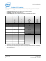
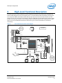
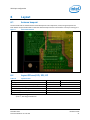
Shield pin configuration
6
Layout
6.1
Antenna keepout
The area under and around the antenna should be kept free of all components, routes, and ground plane. The
Intel® Edison compute module DXF in white with antenna keepout shown in the Arduino* trace layers. See Figure 7.
Figure 7
Area around antenna
6.2
Layout SD card, I2S, SPI, I2C
Table 10
Layout SD card
Signal parameter
Metric (mm)
Standard (mils)
Total length L1
0.254 to 101.6 mm
10 to 4000 mils
DATA/CMD/CTRL to CLK maximum pin-to-pin length mismatch
±2.54 mm
±100 mils
Minimum main route spacing ratio
60 × 60 µm. 1:1 trace width/space.
CLK to DATA/CMD/CTRL matching
±200 mils
Characteristic single ended impedance
42 to 45 ohm (±10%)
Load capacitance
2 to 5 pF
Note:
1) For SPI, total length is 6000 mils.
2) For I2C, total length is 8000 mils.
December 2014
Document Number: 331191-004
Intel® Edison Kit for Arduino*
Hardware Guide
21