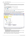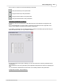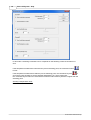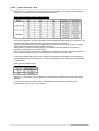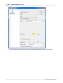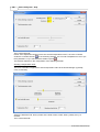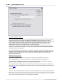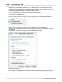
1
Eaton RF System 2.30
Manual
2
Eaton RF-System - Help
Contents
1 Overview Eaton
...................................................................................................................................
RF-System
6
2 What's new?
................................................................................................................................... 6
3 How to Start
................................................................................................................................... 10
4 Menu
................................................................................................................................... 11
File menu.........................................................................................................................................................
Commands
..................................................................................................................................................
of the file menu
The command
..................................................................................................................................................
New (file menu)
The command
..................................................................................................................................................
Open (file menu)
The command
..................................................................................................................................................
Save (file menu)
The command
..................................................................................................................................................
Save as (file menu)
Detailed Info
..................................................................................................................................................
of all devices
Overview..................................................................................................................................................
project configuration
The commands
..................................................................................................................................................
1, 2, 3, 4 (file menu)
The command
..................................................................................................................................................
Quit (file menu)
Edit menu.........................................................................................................................................................
Commands
..................................................................................................................................................
of the Edit menu
Undo
..................................................................................................................................................
Redo
..................................................................................................................................................
Connection
..................................................................................................................................................
Mode
Selection..................................................................................................................................................
mode
Define password
..................................................................................................................................................
Load password
..................................................................................................................................................
Delete password
..................................................................................................................................................
Options ..................................................................................................................................................
Insert menu
.........................................................................................................................................................
Commands
..................................................................................................................................................
of the Insert menu
Background
..................................................................................................................................................
grafic...
Project-Note
..................................................................................................................................................
Group Frames
..................................................................................................................................................
MRF Project...
..................................................................................................................................................
Virtual devices...
..................................................................................................................................................
Devices by
..................................................................................................................................................
Barcode
Actions menu
.........................................................................................................................................................
Commands
..................................................................................................................................................
of the Actions menu
Scan devices
..................................................................................................................................................
Scan reception
..................................................................................................................................................
quality
Recalculate
..................................................................................................................................................
all connections
Load Changes
..................................................................................................................................................
Recalculate
..................................................................................................................................................
Resenders of old Status connections
Reset all ..................................................................................................................................................
devices
Load all devices
..................................................................................................................................................
View traffic
..................................................................................................................................................
Define Project-Topology...
..................................................................................................................................................
Create Manual
..................................................................................................................................................
Routing
Replace device
..................................................................................................................................................
Transfer virtual
..................................................................................................................................................
device functions...
Gateway menu
.........................................................................................................................................................
Commands
..................................................................................................................................................
of the Gateway menu
Go online..................................................................................................................................................
© 2013 Eaton Electrical Group
11
11
12
12
12
12
13
13
14
14
14
14
14
14
14
15
16
17
17
17
19
19
19
20
22
23
25
26
28
28
29
32
33
33
36
37
37
37
38
41
42
43
45
45
46
Contents
3
Go offline..................................................................................................................................................
Identify ..................................................................................................................................................
Software ..................................................................................................................................................
Update
View menu
.........................................................................................................................................................
Commands
..................................................................................................................................................
of the View menu
Toolbar ..................................................................................................................................................
Status Bar
..................................................................................................................................................
Project Topology
..................................................................................................................................................
Background
..................................................................................................................................................
grafic
Group Frames
..................................................................................................................................................
Project-Notes
..................................................................................................................................................
Zoom 100%
..................................................................................................................................................
Zoom 50%
..................................................................................................................................................
No Connections
..................................................................................................................................................
Unverified..................................................................................................................................................
connections
Show all connections
..................................................................................................................................................
Status-Connections
..................................................................................................................................................
Reception..................................................................................................................................................
quality of all devices
Display router
..................................................................................................................................................
Help menu
.........................................................................................................................................................
Commands
..................................................................................................................................................
of the Help Menu
The Command
..................................................................................................................................................
Info
46
46
46
46
46
47
48
49
51
51
51
51
51
51
51
52
52
54
55
55
55
55
5 xComfort...................................................................................................................................
devices
55
Overview .........................................................................................................................................................
xComfort devices
Switching.........................................................................................................................................................
actuator
Dimming .........................................................................................................................................................
actuator
Shutter actuator
.........................................................................................................................................................
Push-button
.........................................................................................................................................................
Binary input
.........................................................................................................................................................
Room controller
.........................................................................................................................................................
Temperature
.........................................................................................................................................................
input
Gateway .........................................................................................................................................................
Home-Manager
.........................................................................................................................................................
RF
Analog actuator
.........................................................................................................................................................
Room-Manager
.........................................................................................................................................................
Overview..................................................................................................................................................
Room-Manager
Heating and
..................................................................................................................................................
cooling with the Room Manager
Outputs and
..................................................................................................................................................
the Room Manager
Ventilation
..................................................................................................................................................
control with the Room Manager
Inputs and
..................................................................................................................................................
the Room Manager
Shading and
..................................................................................................................................................
the Room Manager
Operation-Mode
..................................................................................................................................................
and -Type toggle of the Room-Manager
Timers and
..................................................................................................................................................
the Room Manager
Further settings
..................................................................................................................................................
for the Room Manager
Presence..................................................................................................................................................
simulation and the Room Manager
Logic functions
..................................................................................................................................................
at the Room-Manager
Scenes ..................................................................................................................................................
on the Room-Manager
Safety functions
..................................................................................................................................................
with the Room-Manager
Overview...........................................................................................................................................
Room-Manager with safety function
Room-Manager
...........................................................................................................................................
Safety - Safety in General
Room-Manager
...........................................................................................................................................
Safety - Safety-inputs
Room-Manager
...........................................................................................................................................
Safety - Smoke-detector
Energy functions
..................................................................................................................................................
with the Room-Manager
Energy functions
...........................................................................................................................................
with the Room-Manager in general
© 2013 Eaton Electrical Group
55
56
59
62
66
69
73
75
77
79
80
83
83
87
91
92
93
94
95
97
98
99
100
101
102
102
104
105
106
108
108
4
Eaton RF-System - Help
Room-Manager
...........................................................................................................................................
Energy- Input Inpulse input
Room-Manager
...........................................................................................................................................
Energy- Input Energy measurement sensor
Room-Manager
...........................................................................................................................................
Energy - Input MEP
Room-Manager
...........................................................................................................................................
Energy - General page
Room-Manager
...........................................................................................................................................
Energy - Overview page
Room-Manager
..................................................................................................................................................
Bluetooth
Room-Manager
...........................................................................................................................................
with Bluetooth-function - Text template
Room-Manager
...........................................................................................................................................
with Bluetooth-function - Alerts
Room-Manager
...........................................................................................................................................
with Bluetooth-function - Calls
Room-Manager
...........................................................................................................................................
with Bluetooth-function - Common settings
Synthax ...........................................................................................................................................
from User-SMS for questioning and controlling of objects
Basic information
...........................................................................................................................................
for Room-Manager Bluetooth
Room-Manager
..................................................................................................................................................
Software download
Info about
..................................................................................................................................................
the timer programmes of the Room Manager
Motion detector
.........................................................................................................................................................
Communication
.........................................................................................................................................................
interface
Analog input
.........................................................................................................................................................
2-fold Remote
.........................................................................................................................................................
control
12-fold Remote
.........................................................................................................................................................
control
Routing .........................................................................................................................................................
actuator
Impulse .........................................................................................................................................................
input
Remote control
.........................................................................................................................................................
with display
Overview
..................................................................................................................................................
Remote control with display
Remote..................................................................................................................................................
control with display - Functions
Remote..................................................................................................................................................
control with display - Timer
Remote..................................................................................................................................................
control with display - General
Remote..................................................................................................................................................
control with display - Software update
Energy measurement
.........................................................................................................................................................
sensor
Heating actuator
.........................................................................................................................................................
BOS/COS
.........................................................................................................................................................
Interface
Pendant.........................................................................................................................................................
remote control
MEP
.........................................................................................................................................................
Overview
..................................................................................................................................................
MEP device
MEP device
..................................................................................................................................................
- Total Energy
MEP device
..................................................................................................................................................
- Tariff Energy
MEP device
..................................................................................................................................................
- Tariff outpus
MEP device
..................................................................................................................................................
- General outputs
MEP device
..................................................................................................................................................
- General
Radiator.........................................................................................................................................................
thermostat
Ethernet.........................................................................................................................................................
CI
Overview
..................................................................................................................................................
Ethernet CI
Network..................................................................................................................................................
test
Network..................................................................................................................................................
settings
Multi-Heating
.........................................................................................................................................................
actuator
USB-RF-Communication
.........................................................................................................................................................
Stick
Smart Home
.........................................................................................................................................................
Controller
Switching
.........................................................................................................................................................
actuator 10A/16A
Switching
..................................................................................................................................................
actuator 10A/16A - Actuator function
Switching
..................................................................................................................................................
actuator 10A/16A - Binary input
Switching
..................................................................................................................................................
actuator 10A/16A - Energy measurement
Switching
..................................................................................................................................................
actuator 10A/16A - Extended Status message
109
111
112
115
117
117
117
118
120
120
122
124
124
125
126
129
131
134
135
137
139
139
139
140
141
141
142
143
144
148
149
150
150
151
151
152
153
154
155
159
159
162
162
164
167
168
170
172
176
177
179
6 Configuration
...................................................................................................................................
examples
182
Overview
.........................................................................................................................................................
configuration examples
Configuration
.........................................................................................................................................................
Example of the Switching Actuator
© 2013 Eaton Electrical Group
182
182
Contents
5
Configuration
.........................................................................................................................................................
Example of the Dimming Actuator
Configuration
.........................................................................................................................................................
Example of the Shutter Actuator
Configuration
.........................................................................................................................................................
Example of the Room Controller
191
194
195
7 Things to
...................................................................................................................................
know
197
Icons and
.........................................................................................................................................................
their meaning
How does
.........................................................................................................................................................
the routing work?
What is a.........................................................................................................................................................
group function
Configure
.........................................................................................................................................................
the group function
Configure
.........................................................................................................................................................
group basic settings
Device Popup
.........................................................................................................................................................
menu
Workspace
.........................................................................................................................................................
Popup Menü
Rename .........................................................................................................................................................
while scanning
Connection
.........................................................................................................................................................
wizzard
Device-Note
.........................................................................................................................................................
Project-Setting
.........................................................................................................................................................
and Project-Password
Software.........................................................................................................................................................
Update USB-RF-Sticks
© 2013 Eaton Electrical Group
197
200
201
202
207
217
219
220
221
223
223
226
6
Eaton RF-System - Help
Overview Eaton RF-System
Help overview:
How to start
Overview of all devices
Symbols and their meaning
Configuration examples
How does the routing work?
What is multiple switching?
Working with the Room Manager
Syntax for Room-Manager Bluetooth SMS
What’s new in Version 2.30?
Commands:
File Menu
Edit Menu
Actions Menu
Gateway Menu
View Menu
Help ( ? ) Menu
What's New?
What is new for 2.30:
Supports and contains Room-Manager Software-Version V41a3, the actual file and
Changelog can be found in the Subfolder „Device Software“ in the Eaton RF-System main folder
Contains the USB-RF-Communication-Stick Software USB V1.04 - RF V1.07, the actual
file and Changelog can be found in the Subfolder „Device Software“ in the Eaton RF-System main
folder
Contains the USB-RF-Configuration-Stick Software USB V1.00 - RF V 1.01, the actual file
and Changelog can be found in the Subfolder „Device Software“ in the Eaton RF-System main
folder
New display option Status-Connections, Shows which actuators will send the old status
message or the new extended status message to intelligent devices and offers details about the
connection path. Additionally you can now choose for every actuator in the project if it should send
the old status message or not independent of the reception quality
Contains the Display Remote Control Software V8d, the actual file and Changelog can be
found in the Subfolder „Device Software“ in the Eaton RF-System main folder
Display of Hardware Version of all devices in „Detailed info of all devices“ and „Overview
project configuration“
The RF-monitor now gives more detailed information on received telegrams
Insert virtual devices will now insert Energy measurement sensors with the right basic
settings
The offset temperature for Room 1 in the Room-Manager will now always be saved
correctly
Creation of manual routing connections is now realized for all devices (Energy
measurement sensor, RF Radiator thermostat etc. missing before)
© 2013 Eaton Electrical Group
Eaton RF-System
7
It is no longer possible to use datapoints of intelligent devices as outputs in the connection
wizard if they are already used as inputs
Changes in mains supplied sensors will now always be tracked immediately and
completely loaded to the devices with the ‚Load changes‘ function
Switching actuator 10A/16A will be supported for testing purpose, a new generation of
switching actuators with several new features and additional functions (expected release date Q1
2014)
New Router will be supported for testing purpose, a new generation of Routers (standard
and with Logic function – expected release date Q1 2014)
Function Barcode-Scan will be supported for testing purpose, a new function that can be
used to insert new devices to the project by scanning a Barcode situated on the device (planned
realization of the Barcodes on the devices Q1 2014)
Support of the Ethernet CI, USB-RF-Communication-Stick and Smart Home Controller
RF-Software Version 2.x for testing purpose, these versions are necessary to fully support the
extended Status message of the new Switching actuator generation
What’s new for 2.19?:
Added option to display the IP-address of a Smart Home Controller; executed by right click
on the device and selecting 'IP-address'
What’s new for 2.18?:
Smart Home Controller is supported, a new control and communication device that can be
accessed via Smartphone or Tablet (Device release date is planned for Q1 2013)
Fixes a rare issue that will prevent the USB-RF-configuration stick from losing its
RF-parameters and making it inoperative
Group connections that could not be calculated completely will no longer display a mixture
of red and black connections but only red (uncalculated) connections
Scanning an actuator will now correctly scan the manual routing flag in order to display the
different connection type correctly
Transfer virtual device functiuon and replace device will now correctly transfer all
Room-Manager shading settings
Saving the messages of the RF-monitor will again save the message data
RM-Software update: It is no longer possible to downgrade a Room-Manager with a
version greater than V39b to a lower version. Please always only use the actual Room-Manager
Version (V40a) that can be found in the MRF directory in the subfolder "Device
software\Room-Manager"
Virtual Room controllers used for Heating actuators will now be inserted with the right
mode (Send temperature value)
What’s new for 2.15?:
The actual device software of all devices that can be updated (Ethernet CI,
USB-RF-Kommunikationsstick, USB-RF-Konfigurationsstick, Room-Manager) are now located in
the subfolder "Device software" of the Eaton RF-System main folder.
© 2013 Eaton Electrical Group
8
Eaton RF-System - Help
Multi-Heating actuator will be supported, a new mains supplied device that can be used to
control electrical radiator valves
USB-RF-Configuration-Stick is supported, it’s the successor of the old RS232
configuration interface
USB-RF-Communication-Stick is supported, it has similar functionality as the old
USB-Communication interface
It is now possible to set Transmit- and Receive-performance of the new
USB-RF-Configuration-Stick in the options window
Room-Manager Software Version V40 is supported, this version is necessary to be able to
work with the new Multi-Heating actuator
Replace device: The old USB-Communication interface can now be replaced by the
Ethernet CI or the new USB-RF-Communication-Stick (this does not work backwards)
Connection „Send time and date when changing from X to Room-Manager“ now possible
for Home-Manager, USB-RF-Communication-Stick, USB-Communication-Interface and Ethernet
CI
Window contacts and humidity sensor can now be connected to Room-Manager rooms
even if the room temperature is measured by a RF Radiator thermostat and Room-temperature of
that rooms can be used as variable for logic functions.
Deleting a connection of a group function will now set all remaining connections of that
group to „uncalculated“ instead of recalculating them (only if “Behavior when drawing connections”
is set to „Do not calculate, draw immediately“)
Room-Manager connections Actual values Room 1, Room temperature 1-6, Outdoor
temperature and Room humidity 1-6 now possible for Home-Manager,
USB-RF-Communication-Stick, USB-Communication-Interface and Ethernet CI
Room-Manager outputs can now be connected to Shutter actuators (Attention! Only ON
and OFF commands are sent, Settings need to be changed in the shutter actuator configuration
window)
After every scanning process the MRF will check if newly scanned devices have
connections to existing ones. If that’s the case these connections will only be drawn if the already
existing devices have valid entries for the connections. If not the connections will be automatically
deleted.
When copying a group of devices the switching function will now be correctly inserted
instead of using the standard configuration.
Replace device and Transfer virtual device functions will now correctly work for RF
radiator thermostats that already have connections to other devices
When scanning the reception quality it is no longer possible to cancel the process
prematurely if unknown password protected sensors are activated
When loading changes to selected devices or to devices of an area it is now possible to
toggle between mains and battery supplied devices
What’s new for 2.05:
RF Radiator Thermostat is supported, a new battery supplied radiator thermostat that is
used to regulate the Room temperature in combination with a Radiator
Ethernet CI is supported, a new device that connects the xComfort RF solution with the
Ethernet and adds various new functions and possibilities
© 2013 Eaton Electrical Group
Eaton RF-System
9
The message „X devices with incompatible version have been found“ will no longer be
displayed for devices that have not been scanned completely
“Insert virtual devices”: The device Motion detector will now be inserted properly
The connection calculation of big group functions has been improved
The function „Load changes to selected devices“ should now always load all changes
completely.
What was new for 2.00:
Addition of a background grafic to the workspace
Addition of project notes in the workspace
Addition of device notes
Addition of group frames for the optical grouping of devices
Project topology, partitioning of a project and its devices into areas
Connection wizard, an assistant for the easy creation of group connections
Extended Selection Mode functions 'Move group', 'Delete group', 'Load group changes',
'Reload groups', 'Load basic group settings'
Zooming the workspace (50%, 100%)
Auto-scrolling of the workspace when devices are moved and when connections are
drawn
The names of devices with which a data exchange is to take place, are bolded in the
import/load window
Password-selective scan - before each scan there is an option to specify whether only
devices with a defined password are to be scanned
Renaming of devices while scanning
Undo / Redo of the last 5 actions
Importing of virtual devices from a database or from an existing project
Copying devices individually or as a group, and pasting them as virtual devices
Transfer of functions from virtual devices to real devices
New tool bar with two different character sizes
The RF monitor will show the battery status of each telegram
What's new for 1.62:
Room-Manager Energy Input with Impulse input: Additionally to 'Wh' it is again possible to
set the unit to 'kWh'.
Minor text and configuration errors in the Room-Manager configuration window have been
fixed.
xC MEP device: The scan speed has been improved.
© 2013 Eaton Electrical Group
10
Eaton RF-System - Help
What was new for 1.60?
Room-Manager V38a is supported, new and extended features at rooms, logical functions,
outdoor temperature, scenes, shading groups as well as extended energy features
xC MEP device is supported, a new device which will be used in combination with a Eaton
Smart Meter. The xC MEP transmits energy data to the Room-Manager, Home-Manager or
the communication interface
Automatic scrolling over the boarder of a monitor if you change the position of a device or
if you draw a connection.
Improved reaction of the scan and load window
Version verify for the Room-Manager and the xC MEP device. The version test will be
done if the settings of the Room-Manager or xC MEP device will be opened. The function verifies
if the software version of the device is equal to the version which was scanned into the MRF
project.
Limited setting possibilities for unknown devices to limit wrong changes
Possibility to hide all connections by View -> No connections
Weblinks in the "Info about MRF" window
How to start
After starting the program, the MRF main window will be displayed.
Before starting the program, however, you should connect the Gateway (RS232 interface). If you
wish to do this later, you can do it in the menu item Establish Connection (See Go Online)
Under Options you will see how to select the interface you want to connect the Gateway to.
As soon as the connection to the Gateway is established, you can start to scan all the desired
devices.
After scanning all the mains-supplied devices placed within the reception range, you will be
prompted to activate any battery-supplied devices. In case there are no such devices, activate the
Quit button.
Note: Always scan mains-supplied devices before you activate any battery-supplied devices. To
make it easier, a scanning window displays which and how many of the devices have already been
scanned.
Then your main window should more or less look like that:
© 2013 Eaton Electrical Group
Eaton RF-System
11
Now that you have scanned your system, you can start with its configuration.
To change the position of a device on the screen, left-click and hold the device icon. Now drag it to
the desired position. After releasing the left mouse-button, the new position will be accepted.
Activating a sensor highlights the matching symbol on the screen. So it is easy to distinguish
between several similar sensors, and to give them a name.
Additional setting possibilities:
See System password
See Connection Mode
See Selection mode
See Load
See Symbols and their meaning
See Configuration Examples
Commands of the File Menu
The File menu includes the following commands:
New
Open...
Save
Save as...
Detailed Info of all devices
Overview project
configuration...
1, 2, 3, 4 Filename
© 2013 Eaton Electrical Group
Creates a new project
Opens an existing project
Saves an opened project under its file name
Saves an opened project under a file name you enter
Lists some additional info about the devices (serial number,…)
Shwos detailed data of all devices and connections (Professional
version only)
Opens the selected project
12
Eaton RF-System - Help
Quit
Quits the configuration software of the xComfort components
The Command New (File Menu)
Use this command for creating a new project, e.g. for scanning a complete system of xComfort
components.
To open an existing file use the Open command
Shortcuts
Toolbar:
Keyboard:
STRG+N
The Command Open... (File Menu)
Use this command to open an existing project.
Selecting this command opens the dialog box Open.
Recently edited projects can also be opened directly,
see 1, 2, 3, 4 Filename
New documents can be created with the Command New.
Shortcuts
Toolbar:
Keyboard:
STRG+O
The Command Save (File Menu)
Use this command to save the active project under its current name and directory. When saving a
project for the first time use the Dialog Field Save as, so you can type a name for your document.
Also select the Command Save as if you wish to change the name and the directory of an existing
document.
NEW for 1.53: In the program settings you can now activate if a copy of your project including a
timestamp in the filename should be generated if you use the ‘Save-command’.
Shortcuts
Toolbar:
Keyboard:
STRG+S
The Command Save as (File Menu)
Use this command to save the current project and to give it a name. The xComfort MRF Software
displays the Dialog Box Save as, so you can type a name for your project.
To save a document under its existing name and directory use the Command Save.
© 2013 Eaton Electrical Group
Eaton RF-System
13
Detailed Info of all Devices...
Here you will find a list of detailed data on scanned Devices , among other things the serial
number and software version will be displayed here.
Overview Project Configuration
Here you will see a list of all devices and their settings as well as an accurate overview of all
sensor - actuator connections and their functions. The serial number, software version, device
note, area index and area name for the devices will also be displayed here.
By left-clicking on one of the column headers, the list will be alphabetically sorted by this category.
Individual elements within the list can be moved by using the arrow up and arrow down buttons.
With the button Adopt sequence, the new device sequence is saved.
The sequence of the devices (column 'No.') has an effect on all Loading functions and on
Scanning reception quality. Devices with a lower number are always handled first.
With the Export... button you have the option to save the system configuration in a TXT file in
order to open it later in a spreadsheet program (e.g. MS Excel).
Example:
This function is only available in the professional version.
© 2013 Eaton Electrical Group
14
Eaton RF-System - Help
The Commands 1, 2, 3, 4 (File Menu)
Use the numbers and file names listed at the end of the File menu to open the four projects you
closed last. Select the number of the project you wish to open.
The Command Quit (File Menu)
Use this command to close your session. The xComfort MRF Software asks if you wish to save
projects with modifications not yet saved.
Shortcuts
Mouse:
Keyboard:
Double-click the system menu of the application.
ALT+F4
Commands of the Edit Menu
The Edit menu includes the following commands:
Undo
Redo
Connection mode
Selection mode
Define password...
Load password
Delete password...
Options...
Undoes the previous action
Repeats the last undone action
Activate or deactivate draw mode
This allows the connection (configuration) of two devices
Activate or close selection mode
It is possible to select more than one device.
You can define the system password.
Loads the defined password in the devices.
Deletes the password in the devices and resets the system
password.
Opens the window with the setting options
Undo
When this function is executed, the last action that was triggered through an MRF command is
undone.
A maximum of 5 steps can be reversed, whereby only those commands that actively change
something in the configuration can be undone.
This function is reset by executing the functions Load, Scan, or Scan Reception Quality.
Redo
This function becomes active when the Undo function has been previously executed at least once.
It restores the previously reversed action. This function is reset by executing the functions Load,
Scan, or Scan Reception Quality.
Connection Mode On/Off
With the drawing mode on/off you can select if Connections should be drawn or if the device icons
on the screen should be dragged and dropped.
The position of the device icon is saved in each device, so in case of rescanning xComfort
products there is no need to position them again in the desired place.
© 2013 Eaton Electrical Group
Eaton RF-System
15
Connecting two xComfort devices is possible by left-clicking and holding a device icon. Now select
the required connection by moving the mouse pointer to another device icon. By releasing the left
mouse-button the assignment will be accepted and the connection will be shown as a black line.
Should a required connection not be displayed, select Connections in the menu item View in order
to display all the assignments you have already made.
If you see green or orange connection lines, you have selected the item View for Reception Quality
In addition, the drawing mode can be turned on and off directly in the Toolbar
Selection mode
The main purpose of selection mode is to include new devices in an existing project, but it can also
be used to recalculate the reception quality of individual selected devices or simply to display
existing reception qualities.
Basic function:
As soon as selection mode is activated, no further connections can be drawn, nor can settings be
made in the devices. The drop-down menu for a device changes from the normal functions to the
selection mode functions.
As is usually the case in Windows, several devices can now be selected, either by dragging a
selection window, STRG+ left-click on a device or by pressing SHIFT + left-click/drag window.
As soon as at least 2 devices have been selected, the drop-down menu for selection mode can be
accessed by right-clicking on a device.
The following new functions are available via the drop-down menu:
© 2013 Eaton Electrical Group
16
Eaton RF-System - Help
”Display reception quality of this device” -> shows the reception quality lines from this device to all
the other selected devices.
“Display reception quality for the selected group" -> shows the reception quality of all devices in the
selected group with respect to each other
“Display reception quality with respect to the group as a table” -> shows the reception quality for
this device with respect to the selected group in table form (percentage + device name).
“Recalculate reception quality with respect to the group” -> recalculates the reception quality for
this device with respect to all the selected devices.
“Recalculate reception quality within the group” -> recalculates the reception quality of all the
selected devices with respect to each other.
The functions described above mean, for example, that the reception quality of a new device to its
closest neighbours can be calculated very quickly without having to involve the entire system in
this procedure.
New for 1.55:
Configure group basic settings
Configure the group function
New with version 2.0:
"Assign topology" -> Select an area of the project topology to which you want to allocate the
selected devices
"Copy selected devices" -> Copies the selected devices to the clipboard as virtual devices
"Remove selected devices" -> Removes the selected devices from the project
"Load changes in selected devices" -> Loads configuration changes in the selected devices (if
there are changes)
"Load basic settings in selected devices" -> Loads basic settings in the selected devices (entire
configuration is deleted)
In addition, the screen position of multiple devices can also now be changed by selecting multiple
devices and using drag & drop.
Define password
You can define a password for the system under this menu item. Each device forming part of the
project, or which is to be scanned at a later date, will receive this password when loading
(password, changes or complete).
When you start a new project and click on “Scan”, this window also opens and you can define a
password even before scanning. This password cannot be loaded in the devices during scanning,
only when loading changes on completion of the scanning process.
A password is used to ensure that the system is protected from unauthorised access.
Also see Project-Settings and Project-Password
© 2013 Eaton Electrical Group
Eaton RF-System
17
Load password
All devices forming part of the project which do not yet have the current password are loaded with
the defined password.
This command exists both for an individual device (via the device drop-drown menu) or for the
system as a whole via “Edit -> Load password”.
Also see Project-Settings and Project-Password
Delete password
The password for all devices within the project which have a password is deleted.
Individual devices in which the password has already been deleted previously or which did not yet
have a password will not be included. The password for the project will also be reset to "No
password".
The password can also be deleted individually from one device via “Device drop-down menu ->
delete password".
However, parameterization and assignments to other xComfort devices will not be deleted.
Note:
This means that the devices will be accessible to anyone once again, or, in other words, that any
individual can scan your devices and change the parameterization.
Also see Project-Settings and Project-Password
Options...
By clicking Menu -> Edit -> Options you can reach the program options
© 2013 Eaton Electrical Group
18
Eaton RF-System - Help
Here you can define the serial interface port (COM Port), where the Gateway is connected.
The quality requirement for the reception quality can also be configured („Allow connection only if
reception quality 'good' (recommended)”. This means only good connections can be calculated
successful (not medium quality connections). This raises the number of routing paths but
guaranties a safer transmission.
In the professional version you can determine the behaviour when drawing connections
1. Calculate immediately, error message if not successful (until now )
Like until now the connections is only drawn if the calculation is successful.
2. Calculate immediately, if not successful draw connection anyway
If the connections is drawn the system will try to calculate it immediately. When the calculation is
not successful the connection is drawn anyway but in red.
3. Don't calculate, draw connection immediately (independent from reception quality)
Every connection will be drawn immediately as red an uncalculated connection. You can manually
calculate such connection by clicking on it and “Calculate connection” or for the full project menu
© 2013 Eaton Electrical Group
Eaton RF-System
19
-> edit -> Calculate all connections new
New: Scan also reception quality with normal data.
When deactivated no reception quality is scanned. You can only scan it separately by a new menu
item.
New for 1.53:
Behavior when saving the file: Create a backup copy with date- and time information
If this option is activated everytime you use the command ‘save’ an additional copy of your project
including the time stamp in the file name is generated in the same folder.
New with 2.0:
The functions of the professional version can now be activated by selecting the option "Enable all
functions of the professional version".
Ethernet routing:
In the event that Ethernet communication interfaces are present in the project, you can define here
whether the Ethernet routing should be conducted over IPv4 or IPv6 addresses.
New for 2.15 (only if working with USB-RF-Configuration Stick):
If you are using the new USB-RF-Configuration Stick you can set the Transmit- and
Receive-power of the Gateway (Default 90%).
In some situations it may be of advantage to work with a reduced range (in special when you want
to scan only small areas).
After every MRF restart this is always set to 90% to prevent unintentional settings.
Commands of the Insert menu
The Insert menu contains the following commands.
Background grafic...
Project-Note
Group frames
MRF Project...
Virtual devices...
Devices by Barcode
Adds a background graphic to the
workspace.
Adds a note to the workspace.
Activates/deactivates the mode for drawing
group frames
Option to import devices in an existing MRF
project or as a configuration template
Option to insert desired virtual devices from a
device database
Inserts devices by scanning a Barcode
Insert background grafic
This function offers the possibility of inserting a desired graphic (BMP, JPG, JPEG or GIF format)
in the project as a background grafic. Whether this graphic depicts a building plan or the installer's
company logo, is left to the user's discretion.
The function Insert background grafic can be executed in several ways:
1. Menu Insert -> Background grafic...
2. Right-click on blank MRF workspace -> Insert background grafic...
3. Tool bar ->
© 2013 Eaton Electrical Group
20
Eaton RF-System - Help
After a background grafic has been selected and the Open button has been activated, the
background grafic will be inserted in original size, with the upper left-hand corner in the null
position of the MRF workspace.
By right-clicking in the blank workspace or on the background grafic, the following options will
appear in the pop-up menu:
· Display background grafic: According to settings, shows or hides the background grafic
· <grafic name> -> Delete background grafic: Removes the background grafic from the
project
· <grafic name> -> Change size and position: Unlocks the background grafic so that the
size/position can be changed with the mouse pointer, or locks it again
· <grafic name> -> Align in original size and null position: If the size and/or position of the
background grafic has been changed, the original size and position can be restored with this
command
The background grafic has no influence on the devices or other project settings.
Insert project note
This function offers the option of inserting text notes with a maximum of 255 characters in the
workspace of an MRF project. It can be used, for example, to store information on device groups
in the project or general information on the configuration.
The function Insert project note can be executed in several ways:
1. Menu Insert -> Project note
2. Right-click on blank MRF workspace -> Prepare project note
3. Tool bar ->
© 2013 Eaton Electrical Group
Eaton RF-System
Each project note can be positioned as desired in the project using drag & drop, and the height
and width can be adjusted by clicking and dragging the note borders.
By double-clicking on the title (note), the note is minimised and only the title is visible without
contents. The note can now be moved without changing the position.
By double-clicking on it, the note is maximised once again and displayed in its original position.
All project notes are shown or hidden by going to View -> Project notes or by right-clicking in
blank MRF workspace -> Show project notes.
If you wish to permanently delete a note, click on 'X' and confirm the warning notice with YES.
© 2013 Eaton Electrical Group
21
22
Eaton RF-System - Help
Insert group frames
This function offers the option of drawing frames with titles (max. 21 characters) in the workspace.
These can be used for optical grouping of the device groups when the Project Topology function is
not used.
The function Insert group frames can be executed in several ways:
1. Menu Insert -> Group frames
2. Right-click on blank MRF workspace -> Create group frames
3. Tool bar ->
As with the selection mode, the function remains active until it is deactivated (menu re-selection of
Insert -> Group frames or using the tool bar ->
)
After the frame has been moved (left-click and hold, then release in desired end position) the MRF
will request the input of a frame title. A maximum of 21 characters are possible and at least one
symbol must be used. Once you have confirmed with OK, the frame will be displayed.
By right-clicking in the workspace where one or more group frames are present, a pop-up menu
will appear in which a frame and its title can be further edited using an expanded menu.
The following options are available:
· Delete group frames: Removes the selected frames from the project
· Change size and position: Unlocks the frame so that the size and position can be changed
with the mouse; the frame is relocked by selecting this option again
· Rename group frame...: The title of the group frame can be edited
All group frames in the project can be shown or hidden by going to menu options View -> Group
frames or by Right-clicking in the workspace -> Display group frames.
© 2013 Eaton Electrical Group
Eaton RF-System
23
Insert MRF project
This function offers the option of inserting devices (incl. all settings) from an already-existing MRF
project into your current project.
When doing this, the user can choose whether the devices are to be inserted as real devices or as
virtual devices.
The following conditions must be present:
-) all devices in the project to be imported must be known and fully scanned (no question marks)
-) the project to be imported may not include any devices with the same serial number as devices
in the current project (not with virtual devices)
-) the project to be imported must have been created with the same or an older MRF version than
used in the current project
What is imported:
-) devices, their names and complete device configuration
-) all device connections to one another
-) all device reception qualities among each another
-) the position of the device in the workspace (when importing, however, one insertion point to
which the device positions are to orient will be defined)
The project password will not be imported. All imported devices will take on the password
for the current project!
The function Insert MRF project can be executed in several ways:
1. Menu Insert -> MRF project
2. Tool bar ->
After the function has been executed, the insertion options will be displayed.
Here you can select whether the original project or a configuration template for the selected project
is to be inserted, and whether group frames and project notes are also to be included.
After confirming with OK and selecting the desired project, the MRF will ask for the screen
positions into which the devices are to be inserted.
By left-clicking on the desired position in the workspace, the devices are inserted and the function
is then concluded. The current project password will be adopted for all imported devices.
Insert original project: All devices in the selected project will be inserted very normally as real
devices.
© 2013 Eaton Electrical Group
24
Eaton RF-System - Help
Insert configuration template:
devices.
All devices in the selected project will be inserted as virtual
© 2013 Eaton Electrical Group
Eaton RF-System
25
Insert virtual devices
With this function, as many virtual devices of a selected type as desired can be inserted from a
device database. Virtual devices are primarily configuration templates and can be handled like
normal devices with the exception that loading and scanning are not possible.
With the function Transfer Virtual Device Functions, the configuration of a virtual device can be
transferred to a particular real device.
The function Insert virtual devices can be executed in several ways:
1. Menu Insert -> Virtual devices...
2. Right-click on blank MRF workspace -> Insert virtual devices...
3. Tool bar ->
4. Right-click on an area in the Project Topology window -> Insert virtual devices...
After the function has been executed, the Options window of the virtual device database will open
up.
By pressing on 'Import', the specified number (max. 100) of virtual devices of the chosen device
type and version will be imported into the project.
© 2013 Eaton Electrical Group
26
Eaton RF-System - Help
This function can be repeated as often as desired.
Insert devices by Barcode:
With this new function you can insert devices to a project simply by scanning a barcode stickered
to the devices. The device then can be immediately configured and later only a scan of the
reception quality and a short recheck of the device is necessary.
By clicking the Symbol
or navigating to ‘Insert -> Device by Barcode’ the function is
executed and the following window will be displayed:
Barcode-Scan main window:
© 2013 Eaton Electrical Group
Eaton RF-System
27
You have the possibility to scan the Barcode by a normal USB-Barcode-Scanner or to enter the
Code-numbers manually to the entry field.
USB-Barcode Scanner:
Scan the Barcode of the desired device -> The Code will be checked after clicking on the ‘Verify’
button and if valid a new window with the device details will pop up.
Depending on the type of the used Barcode-Scanner the optimum reading distance between
scanner and Barcode can vary slightly. It is recommended to read the operation manual of the
Barcode-Scanner before use. It is also helpful to configure the Barcode-Scanner in a way that it
will add a Tabulator sign after a data scan. In that case pressing the ‘Verify’ button would no longer
be necessary and the Barcode would be checked automatically and the window of the device
details will pop up.
Manual entry:
Enter the numbers (before the -) on the Barcode-Sticker without any spaces in the Barcode filed
and press the ‘Verify’ button when you are finished -> If the Code is valid a new window with the
device details will pop up
By pressing the ‘Quit’ button the Barcode-Scan function will be exited
By pressing ‘Info’ or hitting F1 this help window will be displayed
In the area ‘Devices already in the project’ you can see an overview of already scanned devices
(by Barcode or normal scan)
Barcode-Scan Device details:
© 2013 Eaton Electrical Group
28
Eaton RF-System - Help
After the positive check of a Code this window will appear and inform about the details of the just
scanned device.
All details (serial number, device type, Software-Version and Hardware-Version) of the device that
results from the Barcode will be displayed and can be rechecked if correct.
Additional the following settings can also be changed:
Name – The name of the device can be edited (max. 21 characters)
Topology area - If available the device can directly be assigned to a Topology area
Replaces device – A virtual or real device can be selected that will be replaced by the scanned
device. Already changed settings to the selected device will be transferred (the selected device will
be removed of the project)
After the desired settings have been made clicking ‚OK‘ or pressing ‚Enter‘ will proceed. The
device will be inserted with the chosen settings and the Barcode-Scan function will be continued.
Clicking ‘Cancel’ will return you to the Barcode-Scan main window without inserting the device.
Display of devices scanned by this function:
Devices that have been inserted by Barcode-Scan will be displayed with a special overlay symbol
(
) to identify them as such. Unless the real device is checked (short scan of the device
property by RF – done automatically during a Scan or Load procedure) the symbol will remain this
way. If this check has been passed successfully the device symbol will be changed to normal and
the device can be loaded.
Commands of the Actions Menu
The Actions menu includes the following commands:
Scan
Scan reception quality
Recalculate all connections
All components are scanned via RF
Scans the reception quality of all devices in the project
(Professional version only)
Recalculates the connections (best routing paths) of all
devices
© 2013 Eaton Electrical Group
Eaton RF-System
29
Recalculate Resenders of old Recalculates the Resenders of old Status connections
Status connections
Load
Reset all devices…
Load all devices…
Display Traffic
Define Project-Topology...
Create manual Routing
Replace device
Transfer virtual device
funtions...
Modified configurations are loaded into the devices via
RF
Resets all components to their delivery state
Reloads all devices with a full set of data
Opens the on-line monitor of RF telegrams
Possibility to create or edit diverse areas in the project
Creates a connection by manual drawing the routing
path
You can replace defective devices with new ones
Transfers the function of selected virtual devices to
real devices
Scan
The reception area is scanned for Eaton RF products only when connected to the Gateway
(RS232 Interface)
All scanned devices are displayed on the screen. If the devices are already configured all
connections, configuration and also the desktop position are also scanned.
Advice: For a complete reflection of the project and all devices regarding the reception quality
scan first all main supplied devices and after that all battery supplied devices. So it is assured that
the
calculations of connections and routing paths is always the best way.
When using Professional version you can scan the reception quality and the normal device data
separately from each other.
After executing the function Scan the Options window for the project settings will appear, in which
specific import options for the upcoming scan process can be defined.
After selecting the desired options and clicking on Scan the process is initiated.
© 2013 Eaton Electrical Group
30
Eaton RF-System - Help
There are some main supplied devices already scanned how you can see in the part list and the
reception area is scanned for further main supplied devices.
© 2013 Eaton Electrical Group
Eaton RF-System
31
Data is being transmitted and if a new device is scanned it will be added to the part list.
New main supplied devices are scanned as long s you press the button „switch to battery supplied
devices“. You can switch back to main supplied devices every time but it’s not recommended to do
so in the standard version (because all main supplied devices should be scanned first)
© 2013 Eaton Electrical Group
32
Eaton RF-System - Help
If you have scanned all desired devices you can click on the „Quit“ button. When using the
standard version the reception quality is scanned and the clean up work is taking part. In the
professional version if you do not scan the reception quality scanning will quit immediately.
When using the standard version some reception quality from the devices is also acquired in
between.
The procedure is working cyclically if there is some time between the normal scanning. This is
necessary and reduces the time for the clean up work.
Scanning the reception quality:
By using the new menu item (Actions -> Scan reception quality) the reception quality of all known
devices can be scanned separately.
Scan reception quality
By using this command the reception quality of all devices on the screen are scanned.
Before you start this sequence you can select if you like to keep previous scanned reception
qualities. If not all existing reception qualities are dismissed.
If you answer with “Yes” only new scanned reception qualities overwrites the old ones. The
reception quality from devices that are not scanned stay.
Termination of reception quality scanning:
1. All reception tables of the main supplied devices are deleted – you have to reach all existing
devices with the gateway in order to scan all reception qualities.
2. Step by step all main supplied devices sends out test messages – the other main supplied
© 2013 Eaton Electrical Group
Eaton RF-System
33
devices notice how good or bad they understand every message. Depending on the number of
devices and their software version 18 or 48 test messages are sent every cycle.
3. From every main supplied device the reception table is scanned. Depending on number and
data in the devices this lasts different. Point 2 and 3 are repeated as often as the reception quality
of every device is known exactly. In the end you have to activate battery supplied devices (so they
can also send test messages). What device should be scanned or which you should activate you
see in the list in the scan window.
The sequence ends automatically after the reception qualities of every device is known.
These function is only available in the professional version.
Recalculate all Connections
In case you have modified the built-in position of the devices in an existing system, this is where
you have the possibility to recalculate all the connections after a Scanning process, including the
routing paths.
The calculation is based on the reception quality identified while scanning.
With each new connection you define in the Connection Mode, the relevant Connection will
automatically be recalculated.
In case you only wish to recalculate part of the paths, you can right-click the required connection
and have this connection recalculated.
Load
By using this command actual changes that has been made to the project can be loaded into the
devices.
Either when clicking on the symbol
or the menu item (Actions -> Load)
When loading the main supplied devices are loaded first and afterwards all battery supplied
devices have to be activated.
The sequence of the loading process is not important. By using the buttons “to battery supplied
devices” and “back to main supplied devices” you can switch while moving through the project.
A simple list shows what devices has to be loaded.
© 2013 Eaton Electrical Group
34
Eaton RF-System - Help
The program tries to load one device after the other. The list will help you to see the progress. The
name of the device that is currently loaded will be bolded. You can scroll through the list at any
time to see which devices are still waiting to be loaded. If there are no more devices reached from
your actual position you have to move through the project.
© 2013 Eaton Electrical Group
Eaton RF-System
All devices that must be loaded are additionally displayed as question marks
name. After the device has been loaded the symbol is shown normal again.
© 2013 Eaton Electrical Group
35
, but keeps their
36
Eaton RF-System - Help
Recalculate Resenders of old Status connections:
With this function you can recalculate resenders of old status connections that cannot be sent
directly from an actuator to an intelligent device. All actuators of the new generation (actual
Switching actuator 10A/16A and Router from SW-Version 9.3) will support this function. Without
such devices the function cannot be used.
Depending on the result of the calculation the user will be informed whether resenders have been
found for all status connections or not and for what status connections the result was negative.
The user has then the possibility to deactivate the sending of the old status for these connections.
This calculation will also be executed when using the function „Recalculate all connections“
If you select Status-Details from a connection to an intelligent device you will see like in this case
that the old status will be resended by ‚SA New‘.
© 2013 Eaton Electrical Group
Eaton RF-System
37
Background of this function:
In earlier MRF versions the old Status message has only been sent by an actuator that was
connected to an intelligent device if there was at least a reception quality >0% between the two
devices (defined by the connection calculation in the MRF). Therefore it could have been possible
that actuators that were switched by an intelligent device by routing never sent their status back.
Since Version 2.30 the sending of the Status of an old actuator can be activated independent of
the reception quality using the option ‘Send old Status message’ in the configuration window of
each actuator. If deactivated the status message will not be sent like in earlier versions when there
was no reception quality between the devices. When activated the status message will always be
sent. Per default this option is activated. The reason for this change is that new generation
actuators and Routers can resend the old status message and forward it to intelligent devices if
there is no direct connection possible (successful calculation of resenders necessary).
Reset all Devices
All the devices which are scanned and can be seen on the screen will be reset to the state at the
time of their delivery.
All the parameterizations and assignments will be deleted. In case a Password has been allocated
before, it will also be deleted from the xComfort devices.
The devices will be reset to the state at the time of their delivery.
Load all Devices
This command re-loads the complete configuration into all the devices.
This option can be used, for example, if any modifications have been carried out later and you
want to make sure that all the devices will be loaded with the complete data, whether any
modifications have been made to the individual devices or not.
Specific info what happens while loading a device you can find here
View Traffic
The command View Traffic opens a window that displays messages (commands, data) transmitted
via radio-frequency.
You will find this command under menu item Actions and View Traffic or by left-clicking the
symbol.
The window is set up the following way:
Line: Shows the line number for a message in the RF-monitor
Time: Shows at what time a message (command, data) has been sent.
Time difference: Shows the time difference to the previous message
© 2013 Eaton Electrical Group
38
Eaton RF-System - Help
Message: Shows the message (command, data) as text, e.g.: Double Push-button (right) sends
<ON> to Shutter Actuator
NEW for 1.47:
You can now see the reception quality of all telegrams received on the right. This shows how well
the gateway has understood the telegrams from the individual devices and does not relate to the
reception qualities between the devices.
NEW for 1.53:
In ‘Auto. Save’ you can set if the received RF commands will be saved after a defined period of
time in a TXT-document. You only have to define a filename and a folder where it should be
saved. When saving cyclically a timestamp will be added to the filename automatically.
Possible time intervalls: every hour, every 6 hours, every 12 hours, every 24 hours
After the file has been saved cyclically the list of received RF commands will be cleared.
New with 2.0:
With every telegram received, information will be displayed on the battery status (full, almost full,
average, weak, and empty) and/or whether the device is powered.
New for 2.30:
Now also system- and configuration-messages will be displayed to have better analyzation
possibilities.
Command buttons:
Hide: Closes the monitor and returns to the MRF main window.
Save…: The messages (data, command) can be saved as text in a (*.txt) file.
Delete: Deletes all data recorded
Stop: Stops viewing the traffic of messages
Define project topology
The project topology serves to divide your project and the devices therein included into separate
areas. Whether the areas are building sections, rooms, floors, etc. is left up to the user's
discretion. Overall there are 3 different area levels (levels 1 - 3). The clear identification of an area
takes place over area indexes (0-255 per level).
For example, if there are devices in the main project that have not been assigned to a special
area, they have the index 0.0.0.
The function Define project topology can be executed in several ways:
1. Menu Actions -> Define project topology
2. Tool bar ->
After the function has been executed, the Define Project Topology main window appears.
© 2013 Eaton Electrical Group
Eaton RF-System
39
Test project1.mrf displays the project names. By selecting the project name, entering a name in
the name field, and clicking on the New button, a new Level 1 area is created.
By selecting a Level 1 area, entering a name and clicking on the New button, a new Level 2 area is
created under the selected Level 1 area, etc.
© 2013 Eaton Electrical Group
40
Eaton RF-System - Help
By selecting on an existing area and clicking on Rename, an area name can be changed at any
time. All area names for every level that you have ever assigned in MRF are saved in a file. If you
now create a new area or wish to rename an existing one, you can make a selection from
previously-assigned names.
With Cut / Copy, individual areas or areas with sub-areas can be copied or cut, and inserted into
selected areas using the Paste button.
With the Delete button, the selected area and all sub-areas can be deleted from the project.
Devices that are allocated to one of these areas will be set to No allocation.
The current project topology can be exported to a file using the Export button, to be able to reuse
it in another project. With the Import button, an already-existing project topology can be imported
into the current project. If a project topology is already present in the current project, it will be
overwritten.
With the OK button, the just-defined project topology is adopted and becomes active.
The function can be repeatedly called-up at any time in order to effect changes in or additions to
the project topology.
In order to work with the topology, the Project Topology window must be activated.
© 2013 Eaton Electrical Group
Eaton RF-System
41
Devices can be allocated to an area by using drag & drop or the function Assign topology in the
pop-up menu, in selection mode, for a group or for individual devices. As soon as a device has
been allocated to an area, its area index will change in accordance with the new area. This
information will also be loaded in the devices and thus will also be recognised upon rescan of the
project.
The area allocation does not have a direct effect on a device itself. However, it is of importance to
the MRF in connection with the calculation of the Ethernet routing, and produces enormous
benefits for the overview of large projects.
Create manual routing
This purpose of this function is not to have MRF automatically calculate a connection, but rather to
set-up a connection by drawing out the individual routing segments.
To be able to use this function, the option "Allow the use of manual routing" must first be activated
in the programme options.
Following this activation, the function can be started by going to the menu options Actions ->
Create manual routing....
CAUTION! It is recommended that this function be used only if you are fully familiarised
with the routing behaviour of the Eaton RF system.
The first connection that is drawn must always originate from a sensor. Thereafter, routing
segments can be arbitrarily drawn through actuators.
Drawn segments can be removed at any time by right-clicking on the line, or by aborting the
function with the ESC key.
When you are finished drawing out the routing segments, confirm with ENTER. The MRF will now
verify whether the connection can be set up or if MRF connection rules have been breached.
If the verification is successful, one or more connections will be established (depending upon
which segments were drawn) and a message will provide information on the number of
© 2013 Eaton Electrical Group
42
Eaton RF-System - Help
connections established.
A connection that was established using manual routing will always be displayed as a black dotted
line
Only one connection with either automatic routing or manual routing may run out from a sensor
channel, never a mixed connection.
You can have MRF recalculate at any time a connection that was set up with manual routing. In
this manner, it loses its manually-entered path and the MRF attempts to calculate the routing
under consideration of the reception quality.
If you need to draw out the manual routing from a multi-channel sensor, you must select the
respective channel after pressing ENTER. The possibility that you have to select the sensor
channel multiple times (for each of the resulting connections) is possible if multiple connections
are set up as a result of the drawn-out routings.
Replace device
Using this function you can replace an existing device in the project by a new one. (f.E. if a device
is defect). You have to scan the new device first. It has to be the same type of device like the old
one.
Then you can start this function and follow the instructions on screen.
IMPORTANT!!! After clicking OK you should immediately click on the “Load” button or menu ->
actions -> load.
Background: The old device is being removed from the screen and replaced by the new one. In all
devices that had something to do with the old device the data entries are changed automatically.
© 2013 Eaton Electrical Group
Eaton RF-System
Transfer virtual device functions
With this function you can transfer all the settings and connections of virtual devices to real
devices.
As a result, the virtual devices are removed from the project. At least one virtual device must be
present in the project for this function to work.
This function can be executed through the menu options Action -> Transfer virtual device
functions...
On the left-hand side you will see a list of all the virtual devices in the project. By selecting one
virtual device, all real devices of the same or a compatible type will be displayed in the list of real
devices (middle). As soon as one of the real devices is selected, the button
© 2013 Eaton Electrical Group
can be pressed.
43
44
Eaton RF-System - Help
As a result, both devices will be linked with one another, removed from their respective lists, and
the connection results will be entered in the list on the right.
You have the option to select a connection result and to delete it at any time by pressing the
button. Both devices would then be returned to their respective lists.
With the option 'Transfer the reception quality of virtual devices' you can specify whether the
reception quality of the virtual devices is to be adopted by the real devices. This is only
recommended if the virtual devices possess significant reception quality (when they are imported
from an existing project).
When you are finished with the transfer of functions, press the button OK. All connections that are
displayed in the table 'Results of the function transfer' are now executed.
© 2013 Eaton Electrical Group
Eaton RF-System
The real devices have now been assigned the functions of the virtual devices. They must be
loaded together with the changes so that the transferred functions are adopted.
The function can be executed as long as there are virtual devices in the project. In principle, it
does not matter whether 100 devices are transferred at once or if the functions of individual
devices are transferred separately.
For information: Similar to the function 'Replace device' the Bluethooth configuration of a RoomManager with Bluetooth will not be transfered.
Commands of the Gateway Menu
The Gateway menu includes the following commands:
Go On-line
Go Off-line
Identify
Connects the Tool (PC Software) to the RS 232 interface (Gateway)
Disconnects the Tool (PC Software) from the RS 232 interface
(Gateway)
Possibility to identify the connected USB-RF-Configuration-Stick
Software
Update
Executes the software update process for the connected
USB-RF-Configuration-Stick
© 2013 Eaton Electrical Group
45
46
Eaton RF-System - Help
Go Online
With this command you can set up a connection to the Gateway (RS232 interface or
USB-RF-Configuration-Stick).Usually this happens automatically when starting the program.
If you have connected the Gateway later or the connection has been cut, go to menu item
Gateway and select Connect to establish the connection.
Note: In the menu item Options you can select which interface (USB, COM1, COM2…) the
Gateway is connected to.
If more USB-RF-Configuration-Sticks are connected you will have the possibility to select the
desired one by its serial number.
Also see Gateway
Go Offline
Use this command to disconnect the Gateway.
Go to menu item Gateway and select Go off-line to disconnect the Gateway.
Also see Gateway
Identify
Use this command to identify the connected USB-RF-Configuration-Stick. The orange colored LED
on the device will blink for 10 seconds.
Software Update
Use this command to load a new software to the connected USB-RF-Configuration-Stick.
For more details see Software Update USB-RF-Sticks
Commands of the View Menu
The View menu includes the following commands:
Toolbar
Status Bar
Project Topology
Background grafic
Group Frames
Project-Notes
Hides or displays the toolbar
Hides or displays the status bar
Shows or hides the Project Topology window
Shows or hides the background grafic
Shows or hides the group frames
Shows or hides the project notes
© 2013 Eaton Electrical Group
Eaton RF-System
Toolbar Standard
Toolbar Large
Zoom 100%
Zoom 50%
Unverified connections
Connections for all devices
Status-connections
Shows the standard tool bar
Shows the large tool bar
Zooms the workspace to 100% (full size)
Zooms the workspace to 50% (half size)
Shows all drawn but not yet calculated connections
Shows all connections configured
Shows all status connections
Reception quality for all
devices
Display router
Shows the reception quality of all devices
47
Displays all routers and their usage.
Toolbar
Standard:
Large:
The tool bar is displayed horizontally at the top, in the application window, below the menu bar. It
provides quick access to important functions through the mouse.
In order to show or hide the tool bar you can select the command Tool bar from the View menu (
ALT,A,S).
The MRF 2.0 version provides 2 different display formats for the tool bar (16x15 pixels and 24x24
pixels). You can switch between the 2 formats using the menu View -> Standard tool bar and the
menu View -> Large tool bar.
Symbol
Description
Opens a new document
Opens an existing document. MRF displays the dialog box Open, where you can
find and open the file you are
looking for.
Saves the active document or the active template under its current name. If you
have not yet given it a name, MRF will display the Save as dialog box.
Undoes the previous action
Restores the last undone action
Connection Mode: Changes into the connection mode
Selection mode: Switches to selection mode
Define password: Option to define a password
Program options: Switches to program options
© 2013 Eaton Electrical Group
48
Eaton RF-System - Help
Einfügen eines Geräts mittels Barcode-Scan
Scan: Scans all devices in the vicinity.
Scan reception quality: Scans the reception quality of all devices.
Recalculate all connections: Recalculates all connections
Load changes: Loads the current configuration in the devices.
Show RF monitor: Opens the show monitor window
Switches to Define Project Topology window
Shows or hides the Project Topology window
Adds a background grafic to the workspace
Adds a project note to the workspace
Switches to drawing mode for group frames
Imports the devices of an existing MRF project or only their properties into an
actual project
Imports virtual devices from a database into the current project
Zooms the workspace to 100%
Zooms the workspace to 50%
Provides Information about the Eaton RF System
Status Bar
The status bar is displayed at the bottom margin of the xComfort MRF Software window. You can
hide or display the status bar by the command Status bar in the View menu.
While you go through the menu using the ARROW KEYS, the left area of the status bar describes
the function of the menu items. In this area you will also see a description of the effect the buttons
in the toolbar have, provided you push and hold these buttons. If you don’t want to carry out the
command corresponding to a button in the toolbar after you’ve read its description, just release the
mouse-button when the mouse pointer is no longer over that button.
© 2013 Eaton Electrical Group
Eaton RF-System
49
In the areas right of the status bar you will see which of the following keys are locked:
Display
UF
Description
The LOCK KEY is activated
NUM
The NUM key is locked
RF
The SCROLL key is locked
The current project's password is always displayed in the area on the far right. If the display is
blank, a password has not yet been defined.
Project Topology window
Activates/deactivates the window for the Topology View. In the process, a window to the left of the
workspace will appear and display the current topology structure.
By right-clicking on the individual areas, the user can execute numerous new functions.
The Project Topology window can be activated/deactivated in 2 different ways:
1. Menu View -> Project Topology
2. Tool bar ->
By activating this window, a new window appears to the left of the workspace.
The Project Topology window displays the area structure that was created with the Define Project
© 2013 Eaton Electrical Group
50
Eaton RF-System - Help
Topology function.
It offers the option of selecting individual areas (left-click). When a specific area is selected, more
devices are displayed on the right-hand side of the workspace, than are present in this area and all
sub-areas. If these devices are located far outside the currently displayed area, automatic scrolling
to the device position will take place.
The standard selection is always the Project name and all of the project's devices are displayed.
The area No allocation displays all devices for which a specific area has not yet been allocated.
In addition, there are 2 other activatable options for this view:
1. Show area indexes: If this option is activated, the index numbers for the individual areas will
also be shown.
2. Show framework of subordinate areas: If this option is activated, an orange-coloured frame
(incl. area name) will be shown surrounding all devices that are present in a subordinate area in
the workspace, upon selection of an area. If the project name is selected, a frame will be drawn
around all of the project's devices, upon activated option.
Pop-up menu area:
By right-clicking on an area in the Project Topology window, a pop-up menu will appear with the
following new options:
· Copy devices: copies all devices in this area to the clipboard
· Insert copied devices: pastes the copied devices to this area as virtual duplicates
· Insert virtual devices...: Opens the window for the virtual device database in order to paste
virtual devices in this area
· Load changes to all devices in this area: Loads the selected changes in all devices in this
area
· Load all devices in this area new: Overwrites all devices in this area with the data in the
MRF
· Load default data to all devices in this area: Loads basic setting in all devices in this area
and reimports them
· Newly detect reception quality of this area: Re-establishes the reception quality of all
devices in this area
When you are in your project's Ethernet communication interfaces, there is also the option to
select one of these interfaces as Ethernet communications node for one area. This influences the
calculation of connections in the MRF. All devices that are present in an area with Ethernet
communications nodes, may only communicate with devices in other areas over Ethernet routing.
The requirement for this purpose is, naturally, that the other areas also possess an Ethernet
communications node or that an Ethernet node is available in a superior area of the project.
© 2013 Eaton Electrical Group
Eaton RF-System
51
Background grafic
This function shows/hides the background grafic, if one is available.
The display of the Background grafic can be activated/deactivated in 2 different ways:
1. Menu View -> Background grafic
2. Right-click on blank MRF workspace -> Display background grafic
see also Insert background grafic
Group frames
This function shows/hides the group frames, if available.
The display of the group frames can be activated/deactivated in 2 different ways:
1. Menu View -> Group frames
2. Right-click on blank MRF workspace -> Show group frames
see also Create group frames
Project-notes
This function shows/hides the project notes, if available.
The display of the Project notes can be activated/deactivated in 2 different ways:
1. Menu View -> Project-notes
2. Right-click on blank MRF workspace -> Show project-notes
see also Insert project notes
Normal view (100%)
When activated, the workspace is zoomed to 100%. All device symbols, device names, connection
lines, etc., are shown in normal size.
Zoom view (50%)
When activated, the workspace is zoomed to 50%. All device symbols, device names, connection
lines, etc., are shown in smaller size.
The creation and the display of project notes is deactivated in this view.
No connections
When activated all connection lines will be hidden.
This can be helpful when moving devices because there can be a lot of connections that will cover
some device symbols.
Unverified connections
Shows connections that has been drawn but not yet calculated successfully.
If the connections are calculated successful their colour changes to black.
© 2013 Eaton Electrical Group
52
Eaton RF-System - Help
Show all Connections
Displays all the connections or assignments of all devices carried out in the Connection Mode as a
black connecting line.
Connections you selected before can be deleted or recalculated at any time by right-clicking the
assignment you want. In this case only this particular connection will be deleted or recalculated.
Should you wish to see the assignments of a particular device, you can display the connections of
this particular xComfort device by opening the Drop Down Menu of this device with the right
mouse-button and by selecting the item Connections.
Shortcuts
Keyboard:
F7
To display the connections of individual devices, please use the Drop Down menu.
Status-Verbindungen:
In this view all status connections of the project will be displayed.
A status connection is a back channel from an actuator that will send information about the output
status back to a connected intelligent device.
There are two different types of status connections:
- Old Status connections
- New Status connection/extended Status message
Old Status message:
General Information:
The old status message will be sent when an output status of any actuator of the old generation
changes (Switching actuator, Dimming actuator, Shutter actuator, Analog actuator). This old status
message will be sent to the first intelligent device in the actuator sensor list and cannot be routed
and is also not repeated by the actuator.
In earlier MRF versions the old Status message has only been sent by an actuator that was
connected to an intelligent device if there was at least a reception quality >0% between the two
devices (defined by the connection calculation in the MRF). Therefore it could have been possible
that actuators that were switched by an intelligent device by routing never sent their status back.
Since Version 2.30 the sending of the Status of an old actuator can be activated independent of
the reception quality using the option ‘Send old Status message’ in the configuration window of
each actuator. If deactivated the status message will not be sent like in earlier version when there
was no reception quality between the devices. When activated the status message will always be
sent. Per default this option is activated. The reason for this change is that new generation
actuators and Routers can resend the old status message and forward it to intelligent device if
there is no direct connection possible. The calculation of this special resend can be done either by
using the function ‚Calculate all connections‘, using the general function ‚Recalculate resenders of
old status connections‘ or right clicking a single status connection and selecting the option
‚Recalculate resenders of old status connections‘.
Display of old Status connection:
Selecting View -> Status connections will display all old Status-connections in dark turquois color
© 2013 Eaton Electrical Group
Eaton RF-System
53
Right clicking such a connection offers the possibility to show status details or to recalculate
resenders of for the status connection
If you select Status-Details you will see like in this case that the old status will be resended by ‚SA
New‘.
New Status connection/extended status message:
General information:
The new status connection is generally an own back channel from the actuator (new generation) to
the intelligent device that supports this special channel.
The connection path can be direct or routed and is treated like a normal sensor -> actuator
connection in the system (like from a pushbutton to a Switching actuator). The connection
calculation will be done together with all other connections.
Also see extended Status message
Display of new status connection:
Selecting View -> Status connections will display all new Status-connections in light blue
© 2013 Eaton Electrical Group
54
Eaton RF-System - Help
Right clicking on a new status connection will offer the possibility to show the connection path like
for any other connection
In this example the Status of ‚SA New 1‘ will be routed over ‚SA New 2‘ to the intelligent device.
Reception quality for all devices
Shows the inter-device reception quality.
The reception quality is depicted in coloured connection lines between the devices:
GREEN
ORANGE
GREY
none
very good RF-connection
satisfying RF-connection
inadequate wireless connection
very poor wireless connection or none at all
Should you wish to see the reception quality of a particular device, you can display the reception
quality of this particular xComfort device by right-clicking and opening the Drop Down Menu of this
device and by selecting the item Reception Quality.
NEW:
The ability to display inadequate reception quality is new. Reception quality lines which are shown
in grey are too poor to be transferred successfully to telegrams, but are important as information
for setting routers. In this case the reception quality is in a range which can just about be
understood by the other device. If you place a router between the devices with a grey reception
quality line, we can assume that a connection from the two devices to the router will work.
© 2013 Eaton Electrical Group
Eaton RF-System
55
Use selection mode to display the reception quality of a specific group.
Shortcuts
Keyboard:
F10
To display the reception quality of a particular device, please use the Drop Down menu.
Display router
It is possible to display routers. All devices which have routing paths entered are assigned a
different icon (router icon). The colour of the router icon indicates router usage.
1-5 routing paths ->
green router icon
6-12 routing paths ->
orange router icon
13 routing paths ->
red router icon; In this case the Router is full if the device is an actuator
of the old generation. Actuators of the new generation are at 50% maximum capacity.
You can also delete the reception quality between two routers in the router view. This may be
helpful if there are two routers in the direct vicinity which have to share routing paths - in such a
case it is better if the two routers don't understand each other.
A reception quality line between two routers can be deleted by right-clicking on a line and on the
option "Disconnect router".
By clicking again on Menu -> View -> Display router, you can change this view again.
Enter topic text here.
Commands of the Help ( ? ) Menu
The Help menu includes the following commands, which offer you support for this application:
Help Topics
About MRF…
Displays the list of topics help is available for
Displays the version number of this application
The Command Info (Help Menu)
Use this command to display the Copyright note and the version number of your Eaton RF system
copy.
xComfort Devices
New:
Switching actuator 10A/16A
Switching Actuator
Dimming Actuator
Shutter Actuator
Push-button
Binary Input
Room Controller
© 2013 Eaton Electrical Group
56
Eaton RF-System - Help
Temperature Input
Gateway
Home Manager
Analog actuator
Room-Manager
Motion detector
Communication interface
Analog input
2-fold remote control
12-fold remote control
Routing actuator
Impulse Input
Energy measuring Sensor
Remote Control with Display
Heating actuator
Room-Manager with Bluetooth
1-fold, 2-fold, 4-fold pushbutton
BOS/COS Interface
Pendant remote control
MEP-device
Ethernet CI
Radiator thermostat
Multi-Heating actuator
USB-RF-Communication Stick
Smart Home Controller
Switching Actuator
General information:
The switching actuator can be used for switching a wide range of electrical loads (see Instructions
for Installation). It can be controlled by any sensor of the xComfort product family.
As soon as a Connection is established between a sensor and an actuator, the actuator can be
configured.
Right-click the switching actuator and select the item Settings in the Drop Down Menu.
Then the configuration window should appear, which usually looks like that:
© 2013 Eaton Electrical Group
Eaton RF-System
57
The different setting options are structured as follows:
1. The left box displays the sensors assigned to the switching actuator (in our case: a single
push-button, Bin 230 and hand-held transmitter). By left-clicking one of these sensors you can
select the function you want to carry out.
2. The next box (top center) depends on the sensor and displays the commands a sensor can
send to an actuator. They are depicted as icons, with the command buttons you can select from
situated next to them. As you will see later, different functions can now be assigned to these
boxes. In our case (single push-button) the icons stand for the following commands: short push at
the top of the push-button, long push at the top of the push-button, long push at the bottom of the
push-button, and short push at the bottom of the push-button. Moving the mouse pointer to the
different command icons will display a tool tip which briefly explains how to trigger this command.
3. The box top right includes the following command buttons:
OK: Confirms the settings entered and returns to the MRF main window.
OK + Load: Confirms, returns to the MRF main window and immediately loads the
modifications into the device.
Cancel: Discards the modifications carried out and returns to the MRF main window.
Info: Opens the Help dialog for Switching Actuators
4. The functions bar enables you to select the different functions which the switching actuator
carries out when it receives a specific command. There is a standard function for each sensor
which the switching actuator defines after establishing the connection to a sensor (same as in
Basic Mode). Some functions occupy more than just one command button, as we will see in the
following function descriptions:
Among them, depending on the pre-set functions, various slider controls (control time, runtime,
interval time), which allow you to set time-related functions.
© 2013 Eaton Electrical Group
58
Eaton RF-System - Help
5. In this box (bottom right) you can pre-set the behaviour of the transmitter in case of power
recovery and low battery.
In case the sensor battery is low, you can select whether or not the switching actuator should send
a warning after switching it on (output blinks once).
Regarding power recovery, you can pre-set how the switching actuator should react to it. There are
three options to choose from:
Old value (Standard): Actuator maintains the same state as before the power
failure
On: After power recovery the actuator switches the output ON
Off: After power recovery the actuator switches the output OFF
All functions of the Switching Actuator:
On / Off (Standard), occupies 2 command buttons
Switches ON resp. OFF
On / Switch-on Delay, occupies 1 command button
On Command which is executed immediately or after an adjustable Delay time
Off / On with Switch-off Delay, occupies 1 command button
Off Command which is executed immediately or after an adjustable Delay time
Off with Advance Warning, occupies 1 command button
Staircase function which switches ON immediately and switches OFF after an adjustable
time.
The Switching Actuators Output is blinking 15 seconds before it switches OFF.
Push-button/Key Mode, occupies 2 command buttons
The Switching Actuator is only ON while its sensor is activated; Otherwise it is OFF
Surge, occupies 1 command button
The Switching Actuator toggles with every sensor activation its output Value.
Blinking, occupies 1 command button
The Switching Actuator begins to blink when its sensor is activated. You can adjust the
interval time.
No Function, occupies 1 command button
Has no Function
Functions for Push-button, Hand-held Transmitter, Home Manager and Binary Input Bat/230 Mode
4:
On / Off (Standard)
ON /
OFF,
and
free, only for
selectable
On / Switch-on Delay free selectable for
,
,
and
Off / Switch-off Delay free selectable for
,
,
and
Off with Advance Warning free selectable for
,
,
and
Push-button/Key Mode for
,
or
,
; only for
oder
selectable
Surge only for
and
selectable
Blinking free selectable for
,
,
and
Functions for Binary Input Bat/230 Mode 1 and Mode 3 (Pushbutton):
Surge (Standard) only for
selectable
On / Switch-on Delay free selectable for
and
Off / Switch-off Delay free selectable for
and
Off with Advance Warning free selectable for
and
Push-button/Key Mode for
and
, only for
selectable
Blinking free selectable for
and
Functions for Binary Input Bat/230 Mode 2 and Mode 3 (Switch):
On / Off (Standard)
ON /
OFF, only for
selectable
On / Switch-on Delay free selectable for
and
© 2013 Eaton Electrical Group
Eaton RF-System
Off / Switch-off Delay free selectable for
and
Off with Advance Warning free selectable for
and
Push-button/Key Mode free selectable for
and
Surge free selectable for
and
Blinking free selectable for
and
Functions for Room Controller and Temperature Input:
On / Off (Standard)
ON /
OFF, only for
selectable
On / Switch-on Delay free selectable for
and
Off / Switch.off Delay free selectable for
and
Off with Advance Warning free selectable for
and
Push-button/Key Mode free selectable for
and
Surge free selectable for
and
Blinking free selectable for
and
Configuration Example for Switching Actuator
Dimming Actuator
General information:
The dimming actuator can be used for dimming and switching all kinds of electrical loads (see
Instructions for Installation). It can be controlled by any sensor of the xComfort product family.
As soon as a Connection has been established between a sensor and an actuator, the actuator
can be configured.
Right-click the dimming actuator and select the item Settings in the Drop Down Menü.
Then the configuration window should appear, which usually looks like that:
© 2013 Eaton Electrical Group
59
60
Eaton RF-System - Help
The different setting options are structured as follows:
1. The left box displays the sensors assigned to the dimming actuator (in our case: a single
push-button, Bin 230 and hand-held transmitter). By left-clicking one of these sensors you can
select the function you want to carry out.
2. The next box (top center) depends on the sensor and displays the commands a sensor can
send to an actuator. They are depicted as icons, with the command buttons you can select from
situated next to them. As you will see later, different functions can now be assigned to these
boxes. In our case (single push-button) the icons stand for the following commands: short push at
the top of the push-button, long push at the top of the push-button, long push at the bottom of the
push-button, and short push at the bottom of the push-button. Moving the mouse pointer to the
different command icons will display a tool tip which briefly explains how to trigger this command.
3. The box top right includes the following command buttons:
OK: Confirms the settings entered and returns to the MRF main window.
OK + Load: Confirms, returns to the MRF main window and immediately loads the
modifications into the device.
Cancel: Discards the modifications entered and returns to the MRF main window.
Info: Opens the Help dialog for Dimming Actuators
4. The functions bar enables you to select the different functions which the dimming actuator
carries out when it receives a specific command. There is a standard function for each sensor
which the dimming actuator defines after establishing the connection to a sensor (same as in
© 2013 Eaton Electrical Group
Eaton RF-System
61
Basic Mode). Some functions occupy more than just one command button, as we will see in the
following function descriptions:
Among them, depending on the functions that are set, several slider controls (control time,
runtime, interval time), which allow you set time-related functions.
Another item is setting the dimming time, which defines how long it takes a dimmer to dim from 0%
to 100%. It can be selected individually for each command, but the maximum dimming time is 250
seconds.
5. In this box (bottom right) you can set the dimming limits as well as the behaviour of the
transmitter in case of power recovery or low battery.
The dimming limits define the range within which the actuator will dim (standard min. 20% to max.
100%).
In case the sensor battery is low, you can select whether or not the dimming actuator should send
a warning after switching it on (output blinks once).
Regarding power recovery, you can pre-set how the dimming actuator should react to it. There are
three options to choose from:
Old value (Standard): Actuator maintains the same state as before the power
failure
On: After power recovery the actuator switches the output ON
Off: After power recovery the actuator switches the output OFF
6. By setting this option, the dimming actuator remembers the last value used before switching off
and switches on again to precisely this value when it receives the next ON command.
All functions of the dimming actuator:
On / Off Dimming (Standard), occupies 4 command buttons
Switches ON presp. OFF
On / Switch-on Delay, occupies 1 command button
ON command that comes either immediately or after an adjustable delay time
Off / On with Switch-off Delay, occupies 1 command button
OFF command that comes either immediately or after an adjustable delay time
On and Off with Advance Warning, occupies 1 command button
Stair case function which switches on immediately and turns off after an adjustable time.
Before
the dimming actuator switches off, the output will blink once 15 seconds earlier as an
advance warning.
Key-Dim-Mode, occupies 2 command buttons
The dimmer switches ON after a short push at the push-button or key, and OFF after a
long push at the push-button or key, and it dims up or down after a long push at the
push-button or key.
Surge, occupies 1 command button
The dimming actuator changes its initial state by dimming each time it is activated.
Blinking, occupies 1 command button, takes the dimming time into account
After activating it, the dimming actuator starts blinking after an adjustable interval time
Desired Brightness, occupies 1 command button
The dimming actuator dims to a pre-set brightness value, at the pre-set dimming speed
(dimming time)
Dim brighter occupies one command box (long press of the button)
Dims brighter as long as the button is held depending on the dimming limits and the
dimming time
Dim darker occupies one command box (long press of the button)
Dims darker as long as the button is held depending on the dimming limits and the
dimming time
No Function, occupies 1 command button
No function – as its name implies
Functions for buttons, hand-held transmitter, Home Manager, Room Manager and Bin Bat/230
Mode4:
© 2013 Eaton Electrical Group
62
Eaton RF-System - Help
On / Off / Dimming (Standard)
ON /
OFF /
Dim (Brighter) /
Dim (Darker), only
selectable for
On / Switch-on Delay free selectable for
,
,
and
Off/on with switch-off delay can be selected at random from
,
,
and
On with pre-warning before off can be selected at random from
,
,
and
Dim brighter can be selected at random from
and
Dim darker can be selected at random from
and
Key-Dim-Mode for
ON/OFF,
Dim (brighter/darker) or
ON/OFF,
Dim (brighter/darker);
only selectable for
or
Surge only selectable for
and
Blinking free selectable for
,
,
and
Desired Brightness, free selectable for
,
,
and
Functions for Bin Bat/230 Mode1 and Bin Bat/230 Mode3 (Push-button):
Key-Dim-Mode for
ON/OFF and
Dim (brighter/darker), only selectable for
On / Switch-on Delay free selectable for
and
Off/on with switch-off delay can be selected at random from
and
On with pre-warning before off can be selected at random from
and
Surge (Standard) only selectable for
Blinking free selectable for
and
Desired Brightness, free selectable for
and
Dim brighter can be selected at random from
and
Dim darker can be selected at random from
and
Functions for Bin Bat/230 Mode2, Bin Bat/230 Mode3 (switches) and movement sensors:
On / Off (Standard)
ON /
OFF, only selectable for
On / Switch-on Delay free selectable for
and
Off/on with switch-off delay can be selected at random from
and
On with pre-warning before off can be selected at random from
and
Blinking free selectable for
and
Desired Brightness, free selectable for
and
Functions for room controller, temperature input and analog input:
On / Off (Standard)
ON /
OFF, only selectable for
On / Switch-on Delay free selectable for
and
Off/on with switch-off delay can be selected at random from
and
On with pre-warning before off can be selected at random from
and
Blinking free selectable for
and
Desired Brightness, free selectable for
and
Configuration Example Dimming Actuator
Shutter Actuator
General information:
© 2013 Eaton Electrical Group
Eaton RF-System
63
The shutter actuator can be used for controlling blinds, shutters, awnings, etc. (see Instructions for
Installation). It can be controlled by any sensor of the xComfortproduct family, and of course by
the
Home Manager RF.
As soon as a Connection is established between a sensor and an actuator, the actuator can be
configured.
Right-click the shutter actuator and select the item Settings in the Drop Down Menu.
This should also display the configuration window, which usually looks like that:
The different Setting options are structured as follows:
1. The left box displays the sensors assigned to the shutter actuator (in our case: a double
push-button, Bin 230 and remote control). By left-clicking one of these sensors you can select the
function you want to carry out.
2. The next box (top center) depends on the sensor and displays the commands a sensor can
send to an actuator. They are depicted as icons, with the command buttons you can select from
situated next to them. As you will see later, different functions can now be assigned to these
boxes. In our case (single push-button) the icons stand for the following commands: short push at
the top of the push-button, long push at the top of the push-button, long push at the bottom of the
push-button, and short push at the bottom of the push-button. Moving the mouse pointer to the
different command icons will display a tool tip which briefly explains how to trigger this command.
3. The box top right includes the following command buttons:
OK: Confirms the settings entered and returns to the MRF main window.
OK + Load: Confirms, returns to the MRF main window and immediately loads the
© 2013 Eaton Electrical Group
64
Eaton RF-System - Help
modifications into the device.
Cancel: Discards the modifications carried out and returns to the MRF main window.
Info: Opens the Help dialog for Switching Actuators
4. The functions bar enables you to select the different functions which the shutter actuator carries
out when it receives a specific command. For each sensor there is a standard function which the
actuator defines after establishing the connection to a sensor (same as in Basic Mode). Some
functions occupy more than just one command button, as we will see in the following function
descriptions:
Among them, depending on the pre-set functions, various slider controls (control time, runtime)
which allow you to set time-related functions.
Shutter actuator with safety functions:
The shutter actuator CJAU-01/02 contains functions to lock the actuator for movement commands.
You can assign 2 safety objects and/or 1 acknowledge object for every shutter actuator.
Safety object:
Every sensor (for example a binary input with a wind or solar sensor) that has been assigned to
the actuator and configured with the function “Safety function when ON” or “Safety function when
OFF”.
Now if the sensor is activated the actuator moves in the safety position (configurable to UP,
DOWN, STOP) and can not be operated by any other sensor. As mentioned above 2 safety
objects can be assigned to each shutter actuator. The safety position has to be the same for both
safety objects. Only when both safety objects are deactivated (if both were activated before) or the
acknowledge sensor is activated the safety function is deactivated.
The interrogation of the release command can be set cyclically. That means a binary input has to
send every 10 minutes a “Safety function deactivated” command to the shutter actuator (if the
actuator is set to 12 minutes). If that is not the case the shutter actuator activates the safety
function automatically after 12 minutes.
Acknowledge sensor:
This sensor can deactivate a safety function independent from the status of the safety objects. For
example if you want to manually operate an actuator.
Configuration window for safety function:
© 2013 Eaton Electrical Group
Eaton RF-System
All functions of a shutter actuator:
Shutter (Standard), occupies 4 command buttons
Slat up/down resp. Stop and Open/Close for the length of the configured Runtime
Roller Blind, occupies 4 command buttons
Stop and Open/Close for the length of the configured Runtime
Roller Blind + Open, occupies 4 command buttons
Stop und Open/Close (with Open briefly) for the length of the configured Runtime
Open, occupies 1 command button
Open for the length of the configured Runtime
Close, occupies 1 command button
Close for the length of the configured Runtime
Stop, occupies 1 command button
Stop Command
Sequencer, occupies 1 command button
Toggles with every Command in the following sequence Open – Stop – Close – Stop –
Open …
No Function, occupies 1 command button
Has no function
Available for CJAU-01/02:
Safety function when ON, needs 2 command buttons
When safety is activated the actuator moves in safety position and is locked for further
operation
until safety is deactivated from the same sensor or the acknowledge sensor.
Safety function when OFF, needs 2 command buttons
Like Safety function when ON only vice versa
Acknowledge safety function, needs 1 command button
© 2013 Eaton Electrical Group
65
66
Eaton RF-System - Help
The actuator is enabled for operation immediately independent form the status of its safety
objects
Functions for Push-button, Hand-held transmitter, Home Manager and Binary Input 230/Bat Mode
4:
Shutter (Standard)
Step up/Stop /
Step down/stop ,
Open and
Close, only for
selectable
Roller Blind
Stop /
Stop ,
Open and
Close, only for
selectable
Roller Blind + Open
Stop /
Stop ,
Open und
Close + Open briefly, only for
selectable
Open free selectable for
,
,
and
Close free selectable for
,
,
and
Stop free selectable for
,
,
and
Sequencer free selectable for
,
,
and
Functions for Binary Input 230/Bat Mode1 and Mode3 (Pushbutton):
Sequencer (Standard) only for
Open free selectable for
and
Close free selectable for
and
Stop only for
selectable
selectable
Functions for Binary Input Bat/230 Mode2 and Mode3 (Switch):
Open free selectable for
Close free selectable for
Stop free selectable for
and
and
and
, Standard for
, Standard for
Functions for Room Controller and Temperature Input:
Open free selectable for
Close free selectable for
Stop free selectable for
and
and
and
, Standard for
, Standard for
Configuration Example for Shutter Actuator
Push-button
This device is a sensor which can control all xComfort actuators (switching actuator, dimming
actuator, shutter actuator, analog actuator), and it can send commands to the Home Manager,
Room-Manager and communication interface.
There are three different types of pushbuttons: 1-fold (1 rocker), 2-fold (2 rocker) and 4-fold (4
rocker)
A 4-fold pushbutton has double functionality than a 2-fold pushbutton and a 2-fold double the
functionality of a 1-fold pushbutton besides that they are equal.
When sending commands a 4-fold pushbutton uses 4 different channels (rocker 1 to 4) and a
2-fold pushbutton uses 2 different channels (left or right).
© 2013 Eaton Electrical Group
Eaton RF-System
67
Every rocker or channel can send the following commands:
: short push at the top of the push-button
: long push at the top of the push-button
: long push at the bottom of the push-button
: short push at the bottom of the push-button
Connecting a pushbutton to a device:
By drawing a line from a pushbutton to the desired device the pushbutton is assigned to this
device.
For a 2-fold pushbutton you have to draw a connection from either the left or right side of the
device icon to assign a connection from the left or right rocker.
If you draw a connection from a 4-fold pushbutton to a device a window pops up which lets you
select the desired rocker (1 to 4) you want to connect.
By using the popup-menu option ‘Settings’ you can see all devices to which a pushbutton has a
connection to.
The pushbuttons of the new generation (from september 2009) also have LED’s for displaying its
state.
You can activate or deactivate the LED function in the setting window of the pushbutton.
Configuration window 1-fold pushbutton:
© 2013 Eaton Electrical Group
68
Eaton RF-System - Help
Configuration window 2-fold pushbutton:
Configuration window 4-fold pushbutton:
© 2013 Eaton Electrical Group
Eaton RF-System
69
Binary Input
With binary inputs we basically distinguish between battery-supplied and mains-supplied devices.
Both types of devices can control any actuator (switching actuator, dimming actuator, shutter
actuator), but they can also send information to the Home Manager (open contact, closed contact,
e.g. in case of a call-in for a window status).
Mains-supplied binary input:
As its name implies, this type of binary input is 230VAC driven.
It provides two potential-carrying inputs (channel A, channel B) where the voltage applied can be
measured (see Instructions for Installation) and from where different commands can be sent,
depending on the value and configuration (mode) of the binary input.
Battery-supplied binary input:
This type of binary input is battery-driven (3V via CR2477N).
Potential-free contacts can be connected to the inputs (channel A, channel B). The binary input
evaluates the status (closed, open) and the device in a different way, depending on the
configuration (mode), and reacts by sending different commands.
The following description of the modes is applicable both to mains-supplied and battery-supplied
binary inputs.
Mode 1:
In this mode both inputs (A and B) are treated as push-buttons and we distinguish between a short
© 2013 Eaton Electrical Group
70
Eaton RF-System - Help
push at the push-button
and a long push at the push-button
.
Mode 2:
In this mode both inputs (A and B) are treated as switches and we distinguish between ON
(contact closed)
and OFF (contact open)
.
Mode 3:
In this mode channel A is treated as a push-button and channel B as a switch.
With channel A we distinguish between a short push at the push-button
the push-button
and a long push at
.
With channel B we distinguish between ON (contact closed)
and OFF (contact open)
.
Mode 4:
In this mode both inputs (A and B) are combined, so they offer the same functions as a
push-button.
Channel A sends a short push at the top of the push-button
and a long push at the top of the
push-button
Channel B sends a short push at the bottom of the push-button
and a long push at the
bottom of the push-button
How to select the modes:
By right-clicking the binary input, you can select from among the 4 modes under Settings in the
Drop Down Menu
© 2013 Eaton Electrical Group
Eaton RF-System
1. In the Mode selection box you can set the individual modes (1 to 4)
2. The box top right contains the following command buttons:
OK: Confirms the selected settings and returns to the MRF main window.
OK + Load: Confirms, returns to the MRF main window and immediately loads the
modifications into the device.
Cancel: Discards the modifications entered and returns to the MRF main window.
Info: Opens the Help dialog for Dimming Actuators
Additional settings for mode 2:
For Mode 2 and Mode 3 (channel B) you can carry out additional settings for the switching
contact.
© 2013 Eaton Electrical Group
71
72
Eaton RF-System - Help
For the relevant switching contacts (A and B) you can select whether or not the status is to be sent
cyclically.
If you select “send cyclically” the cycle time (default 1 hour, minimum 10 minutes to maximum 18
hours) can be set by means of a slider control.
Only applicable for battery-supplied binary inputs:
© 2013 Eaton Electrical Group
Eaton RF-System
73
For a battery-supplied binary input you can also select how it should behave when the switching
contact opens.
Note: A fast reaction impacts the battery life negatively.
Room Controller
The room controller serves as a sensor and can control all xComfort actuators (switching actuator,
dimming actuator, shutter actuator, etc.); it can also send information (temperature) to the Home
Manager, Room Manager, etc.
In order to scan the room controller, turn the adjustment wheel to the upper/lower stop or actuate
the activating keys (types CRCA-00/02 and CRCA-00/03 only)
It has an internal temperature sensor (0 to max. 40°C) and a transmitter for the desired
temperature, which allows to change the desired temperature by ±3°C with an adjustment wheel.
You can choose between the two modes (Send switching commands, Send measured value) via
the settings window.
Sending a switching command:
© 2013 Eaton Electrical Group
74
Eaton RF-System - Help
In this mode a switching command is sent. The following criteria determine when it is to be sent.
The value of the transmitter for the desired temperature (adjustment wheel max. ±3°C) is added to
the switching point (standard 21°C). The result is a desired value.
At the same time the Real temperature is measured internally.
If the temperature measured internally is lower than the desired temperature, the command
“below”
is sent.
If the temperature measured internally exceeds the desired temperature, the command “beyond“
is sent. But it is also possible to set a hysteresis (standard 0.5°C). This will be explained in
detail in an example that follows later.
A second switching point can be entered for the new room controller with operating mode
switching (CRCA-00/02) when sending a switching command. You can then switch between the
two set values by means of a switch underneath the battery cover.
This is to provide the option of having a lower set temperature during the night or when you are on
holiday, etc. The set hysteresis value applies to both switching points.
Sending a temperature value:
By selecting Send temperature value, the temperature measured internally is sent to the allocated
device.
You can select how often (and how precise) the temperature should be measured and sent, and
© 2013 Eaton Electrical Group
Eaton RF-System
75
whether it is to be sent according to a cycle time (to be adjusted with a slider control).
Room controller with humidity (CRCA-00/03):
In addition to the functions described above, the room controller with humidity has a second
channel for measuring the relative air humidity (0-100%).
As in the case of temperature measurements, there are two modes, Send switching command and
Send humidity value, and the option to set an offset value or switching hysteresis value.
The same setting options as for temperature measurements apply to humidity measurements, but
the position of the adjustment wheel has no effect on the humidity channel.
As shown on the device icon, when connecting the temperature channel to another device, the line
is drawn from the left side of the icon, whereas it is drawn from the right for humidity values.
See also Configuration Example for Room Controller
Temperature Input
The temperature input serves as a sensor and can control all xComfort actuators (switching
actuator, dimming actuator, shutter actuator) and it can send a measured value (temperature) to
the Home Manager.
In order to scan it, just take off the cover and when prompted (You can now activate
battery-supplied devices …) press the activating key.
It provides two inputs (channel A, channel B) for external temperature sensors, which cover a
measuring range from -50°C to +180°C.
In case the temperature set is either not reached or exceeded, it can either send a switching
command to the Home Manager, or the temperature measured – just like the room controller.
Both input channels (A und B) are independent from each other and can be treated separately.
Sending a switching command:
© 2013 Eaton Electrical Group
76
Eaton RF-System - Help
In this mode a switching command is sent. It depends on the following criteria at what time it is
sent.
If the temperature measured is lower than the pre-set switching point, the command ”below”
is sent.
If the temperature measured exceeds the pre-set switching point, the command ”beyond“
is
sent. But it is also possible to set a hysteresis (standard 0.5°C), which means that
the command beyond will not be sent until the measured value minus hysteresis is higher than the
switching point.
Sending a temperature value:
© 2013 Eaton Electrical Group
Eaton RF-System
77
Selecting Send temperature value sends the temperature measured to the Home Manager.
You can select how many times (and how precise) the temperature should be measured and sent,
and whether it is to be sent according to a cycle time (adjustable by means of a slider control).
Gateway
The Gateway (RS232 interface or USB-RF-Configuration-Stick) is used to communicate between
the MRF program and all other xComfort devices.
RS232 Interface:
It features an RS232 jack connector and can be connected to the PC or laptop with any
conventional serial cable.
As the device is battery-supplied, it will work for an extended period of time (6 hours with
permanent operation) without any external power supply.
USB-RF-Configuration-Stick:
It can be connected to a PC or Laptop that has a standard USB connector (USB1.1, 2.0 or 3.0).
For normal operation there is no driver installation necessary. Only if the device software needs to
be updated a special driver is necessary. This driver comes with the actual MRF version and will
be prepared automatically. (See Software Update for USB-RF-Sticks for further details).
We recommend changing the Power-Settings of the USB-Hubs for your PC or Laptop to prevent
unwanted connection issues when working with the USB-RF-Configuration-Stick..
Start -> Control Panel -> Double click on “System” -> Select the „Hardware“ tab -> Click the button
„Device Manager.
© 2013 Eaton Electrical Group
78
Eaton RF-System - Help
Open the Folder „Universal Serial Bus Controllers -> Double click every single „USB Root Hub“
and „Generic USB Hub“ and deactivate the option „Allow the computer to turn off this device to
save power“ in the „Power management“ tab.
© 2013 Eaton Electrical Group
Eaton RF-System
79
With that option you assure that the USB-port cannot unintentionally be switched off by the system.
Further technical information can be found in the mounting instruction.
Home Manager RF
The Home Manager RF serves as a central operating, control and display unit. It can send
commands to all actuators and receive commands from all sensors, which it then processes
internally.
For further technical information on the Home Manager RF, please turn to the Instructions for
Installation.
The connection to other xComfort devices is established by means of datapoints.
As soon as a connection has been drawn from a device to the Home Manager RF, the Home
Manager datapoint window will open.
There you can select the datapoint for the assigned device (always suggests the next free
datapoint). In case of several assignments to the same datapoint, the relevant datapoint is simply
depicted with its multiple assignments.
The name of the datapoint can be looked up in the Eaton Manager RF Software.
With OK you confirm what you entered.
Under Create datapoint file in the Drop Down Menu, you can save the datapoint file resulting from
the configurations in a text file (*.txt), which can then be used in the Home Manager RF
configuration program (Eaton Manager RF).
© 2013 Eaton Electrical Group
80
Eaton RF-System - Help
For further information on the configuration of the Home Manager, please turn to the Help section
of the Eaton Manager RF program.
Analog actuator
General information:
The analog actuator (0-10V or 1-10V) can be used to control and switch different devices. It
provides a 0-10V or 1-10V (max. 20mA) control signal und its functions are similar to the dimming
actuator. With the additional relay loads can also be switched. By using the MRF configuration
window you can enable or disable the relay. It can be controlled by any sensor of the xComfort
product family.
As soon as a Connection has been established between a sensor and an actuator, the actuator
can be configured.
Right-click the analog actuator and select the item Settings in the Drop Down Menu.
Then the configuration window should appear, which usually looks like that:
© 2013 Eaton Electrical Group
Eaton RF-System
81
The different setting options are structured as follows:
1. The left box displays the sensors assigned to the dimming actuator (in our case: a single
push-button). By left-clicking on this sensor you can select the function you want to carry out.
2. The next box (top center) depends on the sensor and displays the commands a sensor can
send to an actuator. They are depicted as icons, with the command buttons you can select from
situated next to them. As you will see later, different functions can now be assigned to these
boxes. In our case (single push-button) the icons stand for the following commands: short push at
the top of the push-button, long push at the top of the push-button, long push at the bottom of the
push-button, and short push at the bottom of the push-button. Moving the mouse pointer to the
different command icons will display a tool tip which briefly explains how to trigger this command.
3. The box top right includes the following command buttons:
OK: Confirms the settings entered and returns to the URF main window.
Cancel: Discards the modifications entered and returns to the URF main window.
Info: Opens the Help dialog for Dimming Actuators
4. The functions bar enables you to select the different functions which the analog actuator carries
out when it receives a specific command. There is a standard function for each sensor which the
analog actuator defines after establishing the connection to a sensor (same as in Basic Mode).
Some functions occupy more than just one command button, as we will see in the following
function descriptions:
© 2013 Eaton Electrical Group
82
Eaton RF-System - Help
Among them, depending on the functions that are set, several slider controls (control time,
runtime, interval time), which allow you set time-related functions.
Another item is setting the dimming time, which defines how long it takes a analog actuator to dim
from 0% to 100%. It can be selected individually for each command, but the maximum dimming
time is 250 seconds.
5. In this box (bottom right) you can set the dimming limits as well as the behaviour of the
transmitter in case of power recovery or low battery, if the relay should also switch and the desired
dimming characteristic curve..
The dimming limits define the range within which the actuator will dim (standard min. 20% to max.
100%).
In case the sensor battery is low, you can select whether or not the analog actuator should send a
warning after switching it on (output blinks once).
Regarding power recovery, you can pre-set how the dimming actuator should react to it. There are
three options to choose from:
Old value (Standard): Actuator maintains the same state as before the power
failure
On: After power recovery the actuator switches the output ON
Off: After power recovery the actuator switches the output OFF
The characteristic curve for dimming can be set linear or logarithmic.
6. Activate memory function: By setting this option, the analoge actuator remembers the last value
used before switching off and switches on again to precisely this value when it receives the next
ON command.
7. Dim to a percentage value: If this function is activated the analogue actuator will react on a
direct percentage value command (0-100%) by dimming to that value instead of immediately
jumping to that value. The set dimming time will be taken into consideration. The option will only be
available if the connected sensor is a Room-Manager, Home-Manager or communication
interface.
All functions of the analog actuator:
On / Off Dimming (Standard), occupies 4 command buttons
Switches ON presp. OFF
On / Switch-on Delay, occupies 1 command button
ON command that comes either immediately or after an adjustable delay time
Off / Switch-off Delay, occupies 1 command button
OFF command that comes either immediately or after an adjustable delay time
Off with preliminary Warning, occupies 1 command button
Stair case function which switches on immediately and turns off after an adjustable time.
Before
the analog actuator switches off, the output will blink once 15 seconds earlier as an
advance warning.
Dimming function, occupies 2 command buttons
The analog actuator switches ON after a short push at the push-button or key, and OFF
after a long push at the push-button or key, and it dims up or down after a long push at the
push-button or key.
Momentary contact mode, occupies 1 command button
The analog actuator changes its initial state by dimming each time it is activated.
Flashing mode, occupies 1 command button, takes the dimming time into account
After activating it, the dimming actuator starts blinking after an adjustable interval time
Desired Brightness, occupies 1 command button
The analog actuator dims to a pre-set brightness value, at the pre-set dimming speed
(dimming time)
No Function, occupies 1 command button
No function – as its name implies
Functions for Push-button, Hand-held Transmitter and Binary Input Bat/230 Mode 4:
On / Off / Dimming (Standard)
ON /
OFF /
Dim (Brighter) /
Dim (Darker), only
© 2013 Eaton Electrical Group
Eaton RF-System
selectable for
On / Switch-on Delay free selectable for
,
,
and
Off / Switch-off Delay free selectable for
,
,
and
Off with preliminary Warning free selectable for
,
,
and
Dimming function for
ON/OFF,
Dim (brighter/darker) or
ON/OFF,
(brighter/darker); only selectable for
or
Momentary contact mode only selectable for
and
Flashing mode free selectable for
,
,
and
Desired Brightness, free selectable for
,
,
and
Dim
Functions for Bin Bat/230 Mode1 and Bin Bat/230 Mode3 (Push-button):
Dimming function for
ON/OFF and
Dim (brighter/darker), only selectable for
On / Switch-on Delay free selectable for
and
Off / Switch-off Delay free selectable for
and
Off with preliminary Warning free selectable for
and
Momentary contact mode (Standard) only selectable for
Flashing mode free selectable for
and
Desired Brightness, free selectable for
and
Functions for Bin Bat/230 Mode2 and Bin Bat/230 Mode3 (Switch):
On / Off (Standard)
ON /
OFF, only selectable for
On / Switch-on Delay free selectable for
and
Off / Switch-off Delay free selectable for
and
Off with preliminary Warning free selectable for
and
Flashing mode free selectable for
and
Desired Brightness, free selectable for
and
Functions for Room controller and Temperature input:
On / Off (Standard)
ON /
OFF, only selectable for
On / Switch-on Delay free selectable for
and
Off / Switch-off Delay free selectable for
and
Off with preliminary Warning free selectable for
and
Flashing mode free selectable for
and
Desired Brightness, free selectable for
and
The configuration of the analog actuator is very similar to the dimming actuator. You can set
additionally if the internal relay should also switch or not and set a characteristic curve. The
characteristic curve can be used to compensate the dimming behaviour of lamps.
Overview Room-Manager
1. General:
The Room Manager is a central control, display and operator device for one or more rooms.
There are 2 different sensor areas:
1.
Left and right each with 2 sensor keys (top and bottom) fully functional as a 2-fold
© 2013 Eaton Electrical Group
83
84
Eaton RF-System - Help
pushbutton. The assignment to other devices is equal to a pushbutton.
A ring shaped sensor area from which you can navigate through the displayed menus and
operate the device.
All parameters, data and settings are shown by the 128x64 pixel display.
2.
2. Operation:
The sensor areas are operated by a push or a circular motion with the fingers. Metal or plastic
parts can
not be used to operate the sensor areas.
2.1 Sensor buttons:
Every pair of key (left and right side) builds a „rocker“. Equal to the pushbutton top is ON and
bottom is
OFF. The centre of the sensor area is designated by a red LED.
During a short press at the sensor key a short sound is played (only if the key sound is enabled)
and the
LED is blinking 1 time.
If you hold the key press at the sensor 2 short sounds are played and the LED is blinking 2 times.
This
indicates a long key press. As soon as you move away your finger from the sensor key now
another short sound is played but only if you had a long key press before. Again the LED is
blinking 1 time.
The RF-commands the Room Manager sends during a short or long key press are completely
identical to a 2-fold pushbutton. The only difference is to get a feeling for the key operation
because a touch sensor feels different to a mechanical key.
2.2 Sensor wheel:
You have 3 different ways for operation:
1.
Short key press: Operation somewhere in the ring shaped sensor area without
circular motion, Moving away the finger in under 1 second a short key press is detected, a
short click sound is played
2.
Long key press: Operation somewhere in the ring shaped sensor area without
circular motion, Moving away the finger in over 1 second a long key press is detected, a
short click sound is played, A long key press is only used when manually operating
outputs, shading,…
3.
Circular motion: Operating somewhere in the ring shaped sensor area and
immediately moving the finger, as long as the finger moves in the sensor ring the circular
motion is detected. Switching the direction and slower/faster moving is possible. After
detecting a circular motion over a short angle the Room Manager plays a short click
sound. This sound repeats every time a new movement over a specific angle is detected.
Playing the click sounds gives you a confirmation for the circular movement.
IMPORTANT: The area in the centre of the ring shaped sensor is not designed to detect
operation!!
The sounds for both the sensor wheel and the sensor keys can be enabled or disabled by using
the menu
in the Room Manager. Also the brightness of the Key-LEDs and the background lighting of the
display can be dimmed from 0 to 100% („Miscellaneous -> Lighting“).
3. Display:
The display of the Room Manager has a size of 128x64 pixels and white background lighting that
can be dimmed. Either for active operation or standby mode.
The bottom line of the display shows time, day and date and is shown on every main page. The
same applies to the top line of the display that shows the name and the number of the page. An
arrow besides the page number shows in which direction you can scroll through the pages.
© 2013 Eaton Electrical Group
Eaton RF-System
85
In the MRF it is possible to define if a main page (Exception: General) will be visualised on the
Room-Manager or not.
3.1 Symbols and their meaning:
On some pages different symbols and icons are used to display actual modes and states:
Heating, besides normally its state ON/OFF is displayed
Cooling, besides normally its state ON/OFF is displayed
Ventilation, besides normally its state ON/OFF is displayed
Rising, used at the trend of the outdoor temperature
Falling, used at the trend of the outdoor temperature
is displayed if you are in the installer menu
Info, is mostly used in association with an info text
Overtemperature state, Display in the output page for the status of a new Switching
actuator 10A/16A
Locked State, Display in the output page for the status of a new Switching actuator
10A/16A
Blinking State, Display in the output page for the status of a new Switching actuator
10A/16A
3.2 Menu structure:
The display of the Room Manager is divided in several pages. In its basic state only 3 pages
(Room 1, Time and Date and Miscellaneous) are active. According to the configuration more
pages are generated.
Room 1:
The room temperature (measured by the internal or an external
temperature sensor) is displayed. Further assignments for room controlling
are possible.
Room 2:
The room temperature (measured by a external temperature sensor
assigned to the Room manager) is displayed. Further assignments for
room controlling are possible.
Room 3:
Same as Room 2
Ventilation:
A simple ventilation control using a timer programme. The measured
room temperature is also displayed on this page.
Outdoor temperature:
The outdoor temperature measured by a assigned temperature input is
displayed. The temperature trend and the maximum and minimum value
are also shown. Depended on the configuration it is possible to display two
additional analogue values as the outdoor brightness or the wind speed.
Settings for the outdoor temperature main page can be done in
“Miscellaneous”.
Inputs
The state of the assigned inputs/sensors are displayed.
Outputs:
The state of the assigned actuators/actuator groups are displayed and
can also be operated.
© 2013 Eaton Electrical Group
86
Eaton RF-System - Help
Shading:
The state of the assigned shutters/shutter groups are displayed and can
also be operated.
Timer programme:
The state of the timer programmes are displayed and can also be
configured.
Time and date:
The time and date are displayed and can also be changed.
Miscellaneous:
A menu containing several configuration options is displayed.
By using the ring shaped sensor wheel you can navigate through the pages. With a short key
press on the ring shaped sensor area you can enter the menu of each page. You now can
navigate up and down through the page menu. A short key press to the menu point „Back“ you
jump one level higher again.
Further information about configuration possibilities and operation of the several pages/functions
you can find by following the links below:
Heating and cooling and the Room Manager
Ventilation and the Room Manager
Shading and the Room Manager
Inputs and the Room Manager
Outputs and the Room Manager
Operation modes and the Room Manager
Timer and the Room Manager
Several settings in the Room Manager
Software download by using the IrDA interface
Timer programme and the Room Manager
Extended functions (Enable by checking the Box in the miscellaneous menu):
Presence simulation on the Room-Manager
Logic functions on the Room-Manager
Scenes on the Room-Manager
New as of Version 6.34:
Room Manager with Safety Function
Room Manager with Energy Function
New from Version 6.35 + new Hardware:
Room-Manager with Bluetooth
New for Version 41a:
Support of the new Switching actuator 10A/16A and the extended Status message
© 2013 Eaton Electrical Group
Eaton RF-System
87
Heating and cooling with the Room Manager (Room 1 to 3)
You can define up to 6 rooms/temperature zones for heating and/or cooling in the Room Manager.
For a fully functional room control you need at least one device for temperature measurement and
one heating/cooling actuator.
Room 1 is always active because the room temperature is measured by the internal temperature
sensor of the Room Manager. When another room controller or temperature input is assigned to
the Room Manager you can select if this sensor is used for room temperature/humidity
measurement (Room 1 to 6) or only used as an input.
Once a temperature sensor and a heating/cooling actuator is assigned the room can be
configured. You can change the set points for the temperature of every operation mode for heating
and for cooling as well (if cooling actuator is assigned).
At „optimize Switch-ON time“ you set the time lag of the room. You have 3 different selection
possibilities (fast, middle, slow).
To prevent an oscillation of the heating/cooling every set point has a fix hysteresis of 0.3°C.
If you have a set point of 22°C the heating is activated until it reaches 22°C. At 22°C it switches
Off. If the temperature falls down below 21.7°C the heating is switched On again.
You can also set a timer programme for the operation mode comfort or standby for every room.
© 2013 Eaton Electrical Group
88
Eaton RF-System - Help
More info about timer programmes you can find here.
If you are using both heating and cooling for a room there is a dead zone of 0.5°C between the set
points for heating and cooling of every operation mode. This means that the set point for heating
must at least be 0.5°C lower than the set point for cooling at any time.
For room 1 you can also set an offset for the measured temperature. In room 2 und 3 the offset for
the temperature is directly set in the assigned sensor.
It is possible to define a separate sum output for heating and cooling which switches on a central
heating/cooling device if one or more rooms (with actuators or RF Radiator thermostats) request it.
In each room a maximum of 3 window contacts (binary inputs) can be defined. If one or more
windows are opened the room will be switched to operation mode heat-/frost-protection until all
windows are closed.
If desired it is possible to define that the set-temperature or the operation mode of a room can be
changed via the local pushbuttons if the room main page is displayed. The normal function
(switching light etc.) is deactivate if a room main page is displayed and active if another main page
is displayed.
Connection to a RF Radiator thermostat:
If there is one or more RF Radiator thermostat connected to a Room the general Room regulation
is working different. It is no longer possible to connect normal actuators as heating and cooling
request to that room. The regulation of the valve position takes place in the Radiator thermostat
and not in the Room-Manager. The Room-Manager only sends Set- and Actual-temperature to the
Radiator thermostat and receives a state change from it.
The displayed state of the Room depends on the state of all connected Radiator thermostats. Only
when all thermostats are closed (0%) the Room will show “Heating OFF”. The same goes for the
Sum request of all rooms.
Using the Room menu and selecting “Valve states” the exact state of every connected Radiator
thermostat will be displayed.
If the Room-Manager is set to operation type „cooling only“ the set value for the heating request
will be 0°C.
If there is more than one Radiator thermostat connected to a Room and the Room temperature
should be measured by one of them it can be selected in the box next to “Room temperature” in
the Room configuration window in the MRF.
© 2013 Eaton Electrical Group
Eaton RF-System
89
Connection to a Multi-Heating actuator:
A Multi-Heating actuator can be connected with its 12 heating inputs either to Heating-request,
Cooling-request or combined as Heating-/Cooling-request. Per room as much channels of the
same type as desired can be connected.
To make sure that the Room-Manager and the Multi-Heating actuator always are in the same
operation type the Room-Manager channel „Operation type output“ needs to be connected to the
channel „Heating/Cooling“ of the Multi-Heating actuator. (for details see Operation-Mode and –
Type toggle of the Room-Manager).
Rooms of the Room-Manager that are exclusively connected to Multi-Heating actuator inputs do
not affect the status of the Sum requests (Heating and cooling). The Multi-Heating actuator has its
own sum output which should be used to control a pump etc. Another reason is that the regulation
of the electrical valves takes place in the Multi-Heating actuator and the Room-Manager only
provides the Set- and Actual-temperature for each input with 2 separate RF-commands.
© 2013 Eaton Electrical Group
90
Eaton RF-System - Help
Multi-Heating actuator as heating request:
In this configuration the connected channel of the Multi-Heating actuator is only allowed to work in
operation type „heating only“. If the Room-Manager is set to operation type „cooling only“ the set
value for the heating request will be 0°C.
Further possible heating request connections for a room: other channels of Multi-Heating actuator
or Dimplex-Heating-actuators
Possible cooling request connections for a room: only actuators (Switching-, Dimming-, Analog,
Shutter-actuator, Channels of intelligent devices)
Multi-Heating actuator as cooling request:
In this configuration the connected channel of the Multi-Heating actuator is only allowed to work in
operation type "cooling only". If the Room-Manager is set to operation type "heating only" the set
value for the heating request will be 60°C.
Possible heating request connections for a room: only actuators (Switching-, Dimming-, Analog,
Shutter-actuator, Channels of intelligent devices)
Further possible cooling request connections for a room: only other channels of Multi-Heating
© 2013 Eaton Electrical Group
Eaton RF-System
91
actuator
Multi-Heating actuator as Heating-/Cooling-request:
In this configuration the connected channel of the Multi-Heating actuator is allowed to work in both
operation types. Only one operation type must be active at a time (Only Heating or Only Cooling).
Further possible request connections for Room: other channels of Multi-Heating actuator
Also see Overview of the Room Manager
Outputs and the Room Manager
In the Room Manager you can define up to 10 different outputs (independent if single or
multiswitching of actuators).
By using the sensor wheel you can operate the outputs (On, Off, Dim,..).
Devices that can be assigned to a output are switching actuator, dimming actuator, analogue
actuator, shutter actuator, Comm.-interface and Home Manager.
Shutter actuators can only be used with shading and not with normal outputs.
Devices that have a direct RF-connection to the Room Manager are sending its state to the Room
Manager whenever it changes. The actual state is also displayed in the output page of the Room
Manager.
The name of the output can be changed in the Room Manager directly or in the MRF programme.
Additional the basic state after a reset of the Room Manager can be set for every output in the
MRF software.
© 2013 Eaton Electrical Group
92
Eaton RF-System - Help
Also see Overview of the Room Manager
Ventilation control with the Room Manager
One or more actuators can be assigned to a unique ventilation output that is controlled by a timer.
On the ventilation page of the Room Manager the room temperature (Room 1), the status and the
operation mode of the ventilation is displayed.
© 2013 Eaton Electrical Group
Eaton RF-System
Also see Overview of the Room Manager
Inputs and the Room Manager
Up to 10 different inputs can be defined (temperatures, binary values, analogue values) and
displayed in the Room Manager.
If you have binary values you can define the displayed text for the ON and OFF state in the MRF
software and for analogue values the displayed unit (%, °C,…).
© 2013 Eaton Electrical Group
93
94
Eaton RF-System - Help
Also see Overview of the Room Manager
Shading and the Room Manager
You can define up to 3 groups for shading (independent if single or multiswitching of shutter
actuators).
Changing the name of the shadings can be done in the Room Manager directly or by the MRF
software.
By using the sensor wheel you can operate the Shadings (open, close, step up, step down).
For every shading you can define a timer in which you can set at what time the shading should be
opened or closed. Additionally the shading group can be controlled in dependence of an analogue
value (brightness), room temperature (room 1 to 6) or a binary value. Also a Hysteresis and a
minimum time can be defined for the “enabling”.
Please pay attention that the “enabling” function has only influence on the shading group if the
status of the timer is open! The “enabling” function has no influence if the status of the timer is
close.
© 2013 Eaton Electrical Group
Eaton RF-System
95
Also see Overview Room Manager
Operation-Mode and –Type toggle of the Room-Manager
The Room-Manager has 2 separate inputs that can be used for Operation-mode and
Operation-type toggle. Any binary sensor or binary outputs of other intelligent devices can be
connected to that inputs.
For Room-Managers with a software version under V40 only the input for Operation-mode toggle
is available.
Operation mode and operation type:
With this input the operation mode and the operation type can be switched (only if the separate
input for operation type is not connected).
© 2013 Eaton Electrical Group
96
Eaton RF-System - Help
The operation mode (Automatic, Comfort, Standby, Night, Frost-/Heat protection, OFF) and the
operation type (heating only, cooling only, Heating and Cooling) for ON and OFF commands from
the connected sensor can be configured.
The toggle will affect all Rooms simultaneously.
Operation type only:
If this input is used the combined toggle of the operation type with the operation mode is
deactivated.
For OFF and ON commands of the connected sensors the operation type can be set to "none",
"heating only", "cooling only" and "Heating and Cooling".
ATTENTION! If a Multi-Heating actuator is used in any Room it is necessary to set „heating only“
for OFF commands and „cooling only“ for ON commands.
The state of the operation type can now also be sent out by an own output. This output is
necessary if inputs of Multi-Heating actuator are used in the Room-Manager and in that case it
needs to be connected to the “Heating/Cooling” input of the Multi-Heating actuator. It can also be
connected to „Toggle operation type“ inputs of other Room-Managers for synchronization of the
operation type.
The toggle will affect all Rooms simultaneously.
© 2013 Eaton Electrical Group
Eaton RF-System
97
Timers and the Room Manager
Up to 3 different timers can be defined in the Room Manager that can be assigned to an actuator
or actuator groups. In the defined time span the timer is ON and beyond the time it is OFF.
For every day you can define 3 different time spans directly in the Room Manager or by using the
MRF programme.
The actual state and the operation mode for each timer is displayed in the Room Manager.
Additionally there is an option to set the timer to „always ON“, „always OFF“ or „Auto“.
Only when using the operation mode „Auto“ the timer will work according to the defined time
spans.
© 2013 Eaton Electrical Group
98
Eaton RF-System - Help
Information about how to set the timer programme can be found here
Also see Overview of the Room Manager
Further settings for the Room Manager
You can do additional settings such as the automatic change between summer and winter time,
the user code and the configuration of the outdoor temperature main page.
At the outdoor temperature main pages are the outdoor temperature and two further values as the
MIN/MAX measured outdoor temperature, inputs (e.g. brightness, wind speed), the room
temperature or humidity of the rooms displayed.
You can also define if the battery status main pages will be displayed on the Room-Manager or
not.
As last point you can see the result of the version test which verifies if the software version in the
Room-Manager is equal to the software version which was scanned with the MRF.
© 2013 Eaton Electrical Group
Eaton RF-System
99
Also see Overview of the Room Manager
Presence simulation and the Room Manager
With the presence simulation on the Room-Manager you can control different outputs in a
configurable time period. All outputs that are defined in the Room-Manager can be used for the
presence simulation and will be switched ON and OFF selective for unsteady times (10 to 60
minutes).
The start of the presence simulation can be initiated by manual operation on the Room Manager,
Markers, binary inputs and binary outputs. There is also a possibility to start the presence
simulation when you set holiday on the Room-Manager.
Below is a picture of the configuration window:
© 2013 Eaton Electrical Group
100
Eaton RF-System - Help
Please note that you only use outputs for the presence simulation that are not already used as a
starting variable in a scene or logic function. When activating the presence simulation it could look
like unwanted switching of outputs to the user.
Like the other extended functions (scenes and logic) you have to check the box in the
configuration window „Miscellaneous“ to use the presence simulation. Only after clicking „OK“ and
re-opening the configuration window of the Room-Manager you can use the extended functions.
Logic functions at the Room-Manager
With the logic functions on the Room-Manager you can switch binary and analogue outputs,
shadings or markers if the selected logic operation of the 2 starting variables (binary and analogue
inputs, binary output, room temperature, room humidity, outdoor temperature, local pushbuttons,
marker or timer) gets true.
A maximum of 5 different logic functions can be used. By checking the box at „Enable“ the logic
operation will be activated and can be configured. You can set the starting variables, their logic
connection (AND/OR/GREATHER THAN/LESS THAN/EQUAL), a hysteresis, a minimum time and
the executed action.
The configuration window looks like this:
© 2013 Eaton Electrical Group
Eaton RF-System
101
The defined action is only executed if the logic operation between the 2 starting variables switches
from false to true.
Like the other extended functions (scenes and presence simulation) you have to check the box in
the configuration window „Miscellaneous“ to use logic functions. Only after clicking „OK“ and
re-opening the configuration window of the Room-Manager you can use the extended functions.
Scenes on the Room-Manager
With a scene you can switch up to 6 different binary and analoge outputs, shadings and markers.
If the starting variable has the defined value the scene is executed.
A starting variable can be a binary input, binary output, timer, marker or you activate the scene
directly from the Room-Manager menu.
A maximum of 5 scenes can be configured. A scene ca be retriggered by sending the state of the
starting variable again.
The configuration window looks like this:
© 2013 Eaton Electrical Group
102
Eaton RF-System - Help
By „add action“ and „remove action“ you can set which things the scene should do or remove
them. Also analoge outputs can be set to a percentage value.
Like the other extended functions (presence simulation and logic) you have to check the box in the
configuration window „Miscellaneous“ to use scenes. Only after clicking „OK“ and re-opening the
configuration window of the Room-Manager you can use the extended functions.
General Information on the Room Manager with Safety Function:
Overview:
The Room Manager with Safety Function offers the following possibilities:
-) Warning function to protect against unauthorized entering (window contacts, motion sensors ….)
-) Warning function in case of smoke
-) Alarming and starting of actions
It features:
-) 10 inputs for the warning function to protect against unauthorized entering
-) 5 inputs for the warning function in case of smoke
© 2013 Eaton Electrical Group
Eaton RF-System
103
-) 3 zones (zone 1, zone 2, zone1+2)
General information:
All sensors used for the safety function need to be assigned to a safety input at the Room
Manager (max. 10 safety inputs). The window contacts of the existing rooms can also be included
in the surveillance.
All smoke detectors (via binary input) need to be assigned to a smoke detector input at the Room
Manager (max. 5 smoke detector inputs).
The individual zones can be activated / deactivated either with the assigned inputs or with the
sensor keys.
All the actuators that are supposed to carry out any actions after an alarm has been triggered need
© 2013 Eaton Electrical Group
104
Eaton RF-System - Help
to be created as an output at the Room Manager.
Also refer to chapter Room Manager with Safety Function – General Information
Also refer to chapter Room Manager with Safety Function – Safety Inputs
Also refer to chapter Room Manager with Safety Function – Smoke Detector
Room Manager with Safety Function – General Information:
This is what the configuration window for the Safety Function – General Information looks like:
You can do the following settings:
Field 1:
This is where the code can be defined for the customer to acknowledge an alarm. It is also
possible to either allow or not allow the customer to change the code at the Room Manager.
Field 2:
This selection window will allow you to define what to use for activating/deactivating the safety
function of the different zones (zone 1, zone 2, zone 1+2). You can either select the different inputs
at the Room Manager or the two sensor keys (left, right).
Field 3:
It is also possible to automatically activate the presence simulation after a predefined time period,
provided the safety function has been activated.
© 2013 Eaton Electrical Group
Eaton RF-System
105
Field 4:
If this option has been activated, the Room Manager will give an acoustic alarm once in a minute
in case the battery of the safety sensors is low.
Field 5:
This item allows the system to automatically carry out a determined action upon
activating/deactivating a safety function (e.g.: Switch the “Signal lamp” on upon activation, switch it
off upon deactivation).
Field 6:
This is where you can define what actions should be started in case of an alarm.
In case of an alarm it is possible to switch on 2 different outputs for an adjustable time period.
It is also possible to activate the acoustic alarm of the Room Manager for an adjustable time
period.
Also refer to chapter Room Manager with Safety Function - Overview
Room Manager with Safety Function – Safety Inputs:
This is what the configuration window for the Safety Inputs looks like:
This window is set up as follows:
Field 1:
© 2013 Eaton Electrical Group
106
Eaton RF-System - Help
Here you can define a name for the different Safety Inputs. There is a max. of 10 Safety Inputs
available. It is also possible to define the texts of the status messages to be displayed.
Field 2:
Under ”Status Alarm“ you can define in which status the alarm should be triggered.
Field 3:
With ”Activate with delay“ you have the possibility to activate or deactivate the individual Safety
Inputs with a delay after the circuit has been armed. Also refer to Field 8.
Field 4:
Within the time period you preset here, the Room Manager expects to receive a status message
from the Safety Input. If the Room Manager does not receive a status message within that preset
time, the alarm will be triggered.
Field 5:
Under “Zone“ you can assign the Safety Inputs to the different safety zones (zone 1, zone 2,
zone1+2)
Field 6:
Here you can display the names of the RF sensors that have been assigned.
Field 7:
In addition to the 10 Safety Inputs you can also add 3 window contacts of the rooms to the Safety
Function and keep them under surveillance.
Field 8:
Here you can set the time period for the delay after activating the Safety Function, this means that
if the safety function is activated, all the inputs with a preset delay time will only be armed after the
preset delay time, whereas all the other inputs will be armed immediately after activation.
Also refer to chapter Room Manager with Safety Function - Overview
Room Manager with Safety Function - Smoke Detector:
This is what the configuration window for the smoke detector looks like:
© 2013 Eaton Electrical Group
Eaton RF-System
107
The window is set up as follows:
Field 1:
Here you can define the names of the different smoke detector inputs. There is a max. of 5 smoke
detector inputs available. In this field you can also define the texts to be displayed in the status
messages.
Field 2:
Under ”Status Alarm“ you can define in which status the alarm should be triggered.
Field 3:
Within the time period you preset here, the Room Manager expects to receive a status message
from the smoke detector input. If the Room Manager does not receive a status message within
that preset time, the alarm will be triggered.
Field 4:
Here you can display the names of the RF sensors that have been assigned.
Field 5:
If this option has been activated, the Room Manager will give an acoustic alarm once in a minute
in case the battery of the sensors is low.
Field 6:
This is where you can define what actions should be carried out in case of an alarm.
It is possible to switch on 1 output for an adjustable time period in case of an alarm.
It is also possible to activate the acoustic alarm of the Room Manager for an adjustable time
period.
© 2013 Eaton Electrical Group
108
Eaton RF-System - Help
Also refer to chapter Room Manager with Safety Function – Overview
General Information on the Room Manager with Energy Function:
The Energy Function will enable you to record the values of your energy, water, gas etc.
consumption and to process and display them at the Room Manager. All the counters equipped
with an S0 interface can be connected to the RF system via a Eaton impulse input and can then
be processed at the Room Manager. In addition it also possible to record the electrical energy
consumption of the consumers or consumer circuits via the Energy measuring sensor and to send
the consumption values to the Room Manager.
Since MRF 1.60 and RM V38 it is possible to connect the xC MEP device which is connected to a
Smart Meter with the Room-Manager.
The following functions can be carried out:
-) Display of values and costs
-) Visualization of trends and forecasts
-) Alarms and starting of actions in case a predefined limit is exceeded
-) 5 Inputs for impulse counter inputs, energy measuring sensors or xC MEP devices
General information:
If a connection between the Room-Manager and a impulse counter input, a energy measuring
sensor or a xC MEP device is drawn in the MRF all free energy inputs of the Room-Manager will
be displayed (max. 5 energy inputs).
As usual, you will then be able to carry out a more detailed configuration in the Settings of the
Room Manager.
Also refer to chapter Room Manager with Energy Function – Input with Impulse Input
© 2013 Eaton Electrical Group
Eaton RF-System
109
Also refer to chapter Room Manager with Energy Function – Input with Energy measuring Sensor
Also refer to chapter Room-Manager with energy function – Input MEP
Room Manager with Energy Function – Input with Impulse Input:
If an impulse input is assigned to the Room Manager with Energy Function, the next free energy
input will appear as an option to select. In the Settings window of the Room Manager you will now
see a new tab with the number of this energy input.
This is what the Settings window for the energy input with impulse input looks like:
General information:
Name: This is where the name of the energy input can be entered (max. 13 characters)
Connected device: This is where the assigned impulse input channel is displayed
Measuring unit: This is where the units of the variable to be measured can be entered (currently
kWh, Wh, m3, l)
Base value: Here you can enter a base value. When displaying the Alltime value, it will be added to
the counted value at the Room Manager. This will make sure that the figure displayed at the
© 2013 Eaton Electrical Group
110
Eaton RF-System - Help
counter is the same as the Alltime value displayed at the Room Manager.
New since RM V38:
Generator/Consumer: It is possible to select if the input is connected to a generator or a
consumer.
The selection influence the texts which will be displayed on the Room-Manager or rather the text
which can be selected at “Display on the Room-Manager” and the calculation of the costs.
Show text or chart page on the Room-Manager – It is possible to display or to hide the text or the
chart page of this energy input.
Entering the counting constant:
Format of the counting constant: Select the format of the counting constant, i.e. either “Impulses /
Measuring unit” or “Measuring units / Impulse"
Value: Please enter the numerical value of the counting constant here.
Counting constant: Here you can check the counting constant resulting from your entries, it should
be equal to the counting constant at the connected counter.
Settings for costs:
Here you can do the settings for your cost calculation.
Currency: Enter the currency in which you wish to have the costs displayed.
Base cost value / Month: Please enter the monthly basic charge for the variable that was counted
Tariff per measuring unit: Please enter the tariff per measuring unit
CO2 per kWh: If you have selected kWh or Wh as a variable to be measured, you can enter the
CO2 factor per kWh here.
Threshold value surveillance:
Threshold value: Enter the threshold value here
kWh /: Select the time period that is kept under surveillance
In case of exceeding the value: Here you can set the action that should be carried out in case of
exceeding the threshold value.
Display alarm: If this option has been activated and if the threshold value has been exceeded, a
short info page will appear at the display of the Room Manager. This info page needs to be
acknowledged.
Display at the Room Manager:
In 3 double-lines you can have the different consumption values displayed. The settings made
here will be visualized at the display of the Room Manager, but they can be changed at any time
again via the Settings menu in the Room Manager.
Possible settings for the display (dependend if consumer or generator is selected):
Values: Energy consumption, Energy production, Costs, Gains, CO2 cunsumption, Consumption
prognosis, Production prognosis, Cost prognosis, Gain prognosis, CO2 prognosis
Time periods: Last hour, 24 hours, since mid-night, 7 days, since the beginning of the week, 30
days, since the beginning of the month, since the beginning of the year, total value, Alltime
Not every period of time can be selected for every value though.
© 2013 Eaton Electrical Group
Eaton RF-System
111
Also refer to chapter General Information on the Room Manager with Energy Function
Room Manager with Energy Function – Input with Energy measuring Sensor:
If an Energy measuring sensor is assigned to the Room Manager with Energy Function, the next
free energy input will appear as an option to select. In the Settings window of the Room Manager
you will now see a new tab with the number of this Energy input.
This is what the Settings window for an Energy input with Energy measuring sensor looks like:
General information:
Name: Here you can enter the name of the Energy input (max. 13 characters)
Connected device: Here you will see the assigned Energy measuring sensor
New since RM V38:
Generator/Consumer: It is possible to select if the input is connected to a generator or a
consumer.
The selection influence the texts which will be displayed on the Room-Manager or rather the text
which can be selected at “Display on the Room-Manager” and the calculation of the costs.
© 2013 Eaton Electrical Group
112
Eaton RF-System - Help
Show text or chart page on the Room-Manager – It is possible to display or to hide the text or the
chart page of this energy input.
Settings for costs:
Here you can do the settings for your cost calculation
Currency: Enter the currency in which you wish to have the costs displayed
Base value of costs / Month: Enter the monthly basic charge for the variable that was counted
Tariff per measuring unit: Enter the tariff per measuring unit here
CO2 per kWh: Here you can enter the CO2 factor per kWh.
Surveillance of threshold values:
Threshold value: Enter the threshold value here
kWh /: Here you can select the time period to be kept under surveillance or select the active
power directly
In case of exceeding the value: Here you can set the action to be taken in case the threshold value
is exceeded
Display alarm: If this option has been activated and if the threshold value is exceeded, a short info
page will appear at the Room Manager Display. This info page needs to be acknowledged.
Display at the Room Manager:
In 3 double-lines you can have the different consumption values displayed. The settings made
here will be visualized at the display of the Room Manager, but they can be changed at any time
again via the Settings menu in the Room Manager.
Possible settings for the display (dependend if consumer or generator is selected):
Values: Energy consumption, Energy production, Costs, Gains, CO2 cunsumption, Consumption
prognosis, Production prognosis, Cost prognosis, Gain prognosis, CO2 prognosis, Present power,
present current, present voltage
Time periods: Last hour, 24 hours, since mid-night, 7 days, since the beginning of the week, 30
days, since the beginning of the month, since the beginning of the year, total value, Alltime
Not every period of time can be selected for every value though.
Also refer to chapter General Information on the Room Manager with Energy Function
Room-Manager with Energy Function - Input MEP:
If a channel of the xC MEP device is assigned to the Room Manager with energy function, the next
free energy input will appear as an option to select. In the setting window of the Room Manager
you will now see a new tab with the number of this energy input.
Dependend on which channel of the MEP device is assigned different settings are blocked.
It is a total energy channel available for which the cost settings are blocked and 4 rate energy
channels for 4 different rates.
This is what the setting window for the energy input assigned to the total energy channel of the xC
MEP device looks like:
© 2013 Eaton Electrical Group
Eaton RF-System
113
This is what the setting window for the energy input assigned to a tariff energy channel of the xC
MEP device looks like:
© 2013 Eaton Electrical Group
114
Eaton RF-System - Help
General:
Name: Here you can enter the name of the energy input (max. 13 characters)
Connected device: Here you will see the assigned MEP device channel
Generator/Consumer: It is possible to select if the input is connected to a generator of a
consumer.
The selection influence the texts which will be displayed on the Room-Manager or rather the text
which can be selected at “Display on the Room-Manager” and the calculation of the costs.
Show text or chart page on the Room-Manager – It is possible to display or to hide the text or the
chart page of this energy input.
Settings for costs:
Here you can do the settings for your cost calculation. The costs can be only configured if an xC
MEP device rate channel is connected.
Depending on how many different tariffs are used this valuer needs to be divided by this value in
order to have the correct value wehn summarizing the costs.
Currency: Enter the currency in which you wish to have the costs displayed
Base value of costs / Month: Enter the monthly basic charge for the variable that was counted
© 2013 Eaton Electrical Group
Eaton RF-System
115
Tariff per measuring unit: Enter the tariff per measuring unit here
CO2 per kWh: Here you can enter the CO2 coefficient per kWh
Surveillance of threshold values:
Threshold value: Enter the threshold value here
kWh /: Here you can select the time period to be kept under surveillance or select the active
power directly
In case of exceeding the value: Here you can set the action to be taken in case the threshold value
is exceeded
Display alarm: If this option has been activated and if the threshold value is exceeded, a short info
page will appear at the Room Manager Display. This info page needs to be acknowledged.
Display on the Room Manager:
In 3 double-lines you can have the different consumption values displayed. The settings made
here will be visualized at the display of the Room Manager, but they can be changed at any time
again via the Settings menu in the Room Manager.
Settings possible for the display (dependend on if consumer of generator is selected):
Values for xC MEP device total energy channel: total active power consumption, total power
production, total energy consumption, total energy production, present tariff
Values for xC MEP device rate enegy channel: Energy consumption, Energy production, costs,
CO2 consumption, consumption forecast, production forecast, cost forecast, gain forecast, CO2
forecast,
Time periods: Last hour, 24 hours, since mid-night, 7 days, since the beginning of the week, 30
days, since the beginning of the month, since the beginning of the year, total value, Alltime
Not every period of time can be selected for every value though.
Also refer to chapter General Information on the Room Manager with Energy Function
Room-Manager with Energy Function - Energy General page:
The page is used as additional display to get a quick overview of the present consumption or
production. Further it is possible to define actions for defined consumption or production areas.
© 2013 Eaton Electrical Group
116
Eaton RF-System - Help
Setting possibilities:
Name: Here you can enter the name of the page (max. 13 characters)
Displayed data: Defines which source will be used for the calculations on the display.
(Total power – sum of all energy inputs (active power), active power values of individual energy
inputs)
Pos. 1: the present power of the selected source is fixed defined for Pos 1
Pos. 2: the energy consumption of the selected source is fixed defined for Pos 2. The time area
can be changed as desired.
Pos. 3: the present energy areas, outdoor temperature (if available), room temperature (if
available) can be displayed
Energy Areas: It is possible to define different energy areas. The Room-Manager verifies in which
area the source is and depended on the area you can start different actions (switch Markers or
Outputs).
Also refer to chapter General Information on the Room Manager with Energy Function
© 2013 Eaton Electrical Group
Eaton RF-System
117
Room Manager with Energy Function – Overview Page:
At the energy overview page you can display again 3 lines with values. Per line you can select
single values or you can combine/sum up to 5 values of the available energy inputs. The settings if
an input is a generator or a consumer will be considered. For each line it is possible to define a
different time area. Further you have the option to display a chart (Exception: Costs/Gain). The
name of each line will be used as main page name of the charts.
Also refer to General Information on the Room Manager with Energy Function
Room-Manager with Bluetooth-function – Text template:
The configuration window looks like:
© 2013 Eaton Electrical Group
118
Eaton RF-System - Help
You can define up to 3 predefined SMS texts. It can be selected for sending in the ‘alarms” page.
It can also be chosen to use the first message for the beginning of a status message.
Room-Manager with Bluetooth-function - Alerts:
The configuration window looks like:
© 2013 Eaton Electrical Group
Eaton RF-System
119
Here you can define how the Room-Manager will react on 3 different events.
Possible events are: Marker to ON, Output to ON, Input to ON, Timer to ON, Safety alert, smoke
alert
After one of this events happen the Room-Manager will send out a SMS (status text or 3
predefined texts)
After selecting the event you can either select “delayed” or the desired phone number to which the
SMS will be sent. If you select “delayed” the RM waits a defined duration before sending out the
SMS (max. 120 minutes, 0 minutes = 30 seconds). The SMS will be sent to the phone number that
is selected afterwards.
If you chose in the next line “wait for confirmation” after you have selected a number the
Room-Manager will wait for a confirmation in form of a call or SMS (with the text “OK”) for the
desired number of minutes. If no confirmation is received within this time the Room-Manager can
send the alarm to another phone number (and if desired also to a third one).
If you activate the option “warning if low battery state:” you can select a number to which a
SMS-warning will be sent if one of the battery states on the Room-Manager is low.
© 2013 Eaton Electrical Group
120
Eaton RF-System - Help
Room-Manager with Bluetooth-function - Calls:
The configuration window looks like:
Start action by phone call:
Here you can define an event which is executed by the Room-Manager if one of the defined
numbers is calling. A short call to the Room-Manager is enough, the call will not be picked up. As
event you can select a desired output or marker to be set to ON, OFF or being toggled.
Room-Manager signalizes event by call:
You can define to call a desired phone number if an event will take place. The call will only last for
some seconds and the Room-Manager will hang up afterwards by itself. The event can be
triggered by a marker or output that is switched ON, OFF or toggled.
Room-Manager with Bluetooth-function – Common settings:
The configuration window looks like:
© 2013 Eaton Electrical Group
Eaton RF-System
121
The following settings can be done:
‘Enable control and request via SMS’ – If this option is deactivated nothing can be controlled or
requested by SMS commands
‘Password for SMS interaction (4-16 characters)’ – Enter a password that has to be used for every
request/control SMS that is sent to the Room-Manager. See also Syntax of SMS-commands
‘Bluetooth visibility On’ – If his option is activated the Room-Manager will be found as a Bluetooth
device if you search for active devices
‘Automatically generate Bluetooth-passkey’ – If this option is activated the key that is used to
establish a connection to another device is generated automatically.
“Enter passkey” – You can define a passkey manually, only available if the passkey is not
generated automatically
‘Maximum number of SMS per day’ – You can define the maximum number of SMS that can be
sent per day (0 = sending of SMS is deactivated, infinite = number of SMS is unlimited)
‘Set target-phone number for SMS-sending’ – You can define up to 5 different phone numbers that
can be used for the different RM bluetooth functions
‘Answer-SMS for wrong syntax or password’ – The Room-Manager will answer to a wrong
request/control-SMS so the user knows that it has not been understood
© 2013 Eaton Electrical Group
122
Eaton RF-System - Help
‘Set/interrogate marker by SMS’ – If this option is activated also state of markers can be requested
and set by SMS-commands
‘Shading can be controlled by SMS’ – If this option is activated also the state of shadings can be
controlled by SMS-commands
To be able to operate inputs and outputs by SMS-commands use the check boxes on the
output-/input-configuration page.
‘Mobile phone selection’ – Manufacturer and type of the mobile phone can be selected here ,
ATTENTION: The file “handy.txt” must be located in the same directory of the MRF program to be
able to select anything here.
Syntax from User-SMS for questioning and controlling of objects:
Beginning of every SMS:
":<Password> "
afterwards:
"<object name>"
following:
for request
for control
"?"
"=<state>!"
There is the possibility to request or control more than one object with only 1 SMS.
Examples:
":1234 R1?"
":1234 O2=0!"
":1234 R1? O1=1! I?"
and switches output 1 to ON
Requesting the state of Room 1
Switches output 2 to OFF
Requests the state of Room 1 and every input
If more than one objects is requested, every information is integrated in one answer SMS or it is
separated in more SMS if the length exceeds a maximum of 160 characters.
<Password>:
4-16 characters alpha numeric, can be set in the MRF configuration window or in the
Room-Manager, is immediately following the “:” and ends with the first blank space afterwards
<<Object name>:
The object name defines which object should be operated, you can use either the full name of the
object or a short form.
© 2013 Eaton Electrical Group
Eaton RF-System
<State>:
Syntax of RM to user:
© 2013 Eaton Electrical Group
123
124
Eaton RF-System - Help
Basic information for Room-Manager Bluetooth:
The primary function for the Room-Manager Bluetooth is:
-) External control (via SMS) of Room-Manager objects (Outputs, shading, operation mode,…)
-) Sending of state information-SMS if requested by user
-) Triggering defined actions on the Room-Manager if a call is received
-) Sending of alert-SMS if defined events will occur
-) Triggering a call from the Room-Manager to a defined phone number if a defined event will
occur
-) Display of up to 5 received Text-SMS (for information purpose)
By using the integrated Bluetooth-module the Room-Manager establishes a connection to a
Bluetooth-mobile phone in its immediate surrounding. Over that mobile phone the Room-Manager
then can communicate via GSM with other mobile phones (Sending/receiving SMS,
Execute/receive calls,…).
To establish a connection to a mobile phone you have to first select the manufacturer and phone
type in the MRF configuration window ‘Bluetooth/SMS’ and load the information to the
Room-Manager.
Because not every mobile phone is acting the same it is recommended to only use devices that
has been tested by Eaton.
The real connection to the mobile phone must be done by using the Room-Manager menu ‘
Bluetooth’ and the command ‘Search for devices’.
Also see:
Room-Manager with Bluetooth-Function – Common settings
Room-Manager with Bluetooth-Function - Calls
Room-Manager with Bluetooth-Function - Alerts
Room-Manager with Bluetooth-Function – Text template
Syntax for Request/Control by SMS
Software download over IrDA-interface
To update the software of your Room Manager do the following:
1.
2.
3.
Scan the Room Manager that you want to update with the MRF software
Make sure that you have the IrDA-interface of you PC/laptop activated.
Activate the IrDA-interface of you Room Manager by „Miscellaneous -> For the
installer -> Software update“, you
now have 2 minutes time to establish
connection between your PC and the Room Manager.
4.
Establish intervisibility between the IrDA-interface of your PC and the Room
Manager now
5.
Now use the start menu of your operating system to: „Start -> Configuration ->
System configuration -> Telephone
and modem options -> Register:
Modems“. A „standard mode over IR-link should be displayed.
6.
In the row „assigned to“ you can see which COM-interface number your Room
© 2013 Eaton Electrical Group
Eaton RF-System
125
Manager has been connected to.
Now go back to MRF and right click on your Room Manager and select „Load new
software…“
8.
The following dialog window is shown:
7.
9.
10.
11.
Select the file you want to download (*.rm)
Select the correct COM-interface number
Click on „Load software“
If the software has been loaded successful a window pops up that informs you and the Room
Manager restarts.
You have to rescan the Room-Manager so that the MRF eventually detects changes made by the
software update!
Also see Overview of the Room Manager
Info about the timer programmes of the Room Manager
The Room Manager mainly uses timer programmes for controlling operation modes with time
based functions.
Dependant for what function the timer programme is used the dialog windows are different.
Window for the timer programme of a room:
© 2013 Eaton Electrical Group
126
Eaton RF-System - Help
As you can see in the picture for every day you can set 3 different time spans with different
operation modes. Please note, if you would like to set a time over midnight you have to separate it
in 2 time spans
One before midnight and one after midnight.
The operation mode outside of a time span is always „Night“.
Also see Overview of the Room Manager
Motion detector
The motion detector detects movement and sends RF-commands to its assigned devices.
Every actuator (switching actuator, dimming actuator, shutter actuator, analogue actuator) can be
controlled by the motion detector and information can be sent to the Room Manager, Home
Manager and the Comm.-interface.
Channel A is the detection output and sends depending on the ambient light value a ON command
if movement is detected and after a adjustable time when there is no new movement the channel
sends the OFF command.
Channel B is immediately activated independent from the ambient light level and after a fix time of
120 seconds automatically deactivated if no more movement is detected in this time span.
Channel B mainly is used for alarms.
The activated time will be retriggered if new movement is detected within this time span.
By using the DIP-switches in the device Channel A and B can be activated and deactivated
separately.
Also the light value range (Night, Dawn, Day & Night) can be set by the DIP-Switches.
Movement is only detected if the actual light value is within the set light level.
© 2013 Eaton Electrical Group
Eaton RF-System
127
Setting of Delay time for Channel A:
The Switch-Off delay time for channel A can be set to the following values:
If movement is detected the delay time begins to run and after this time the channel automatically
switches OFF. Now if new movement is detected in this time the delay time begins to run new.
So for example the light is at least ON for the defined delay time if no new movement is detected.
Setting of ambient light level:
Movement is only detected if the actual light value is within the set light level.
Setting of motion sensitivity:
The impulses specifies how often a movement has to be detected before the motion detector
reacts.
© 2013 Eaton Electrical Group
128
Eaton RF-System - Help
If the setting is 1 impulse the motion detector reacts immediately on movement. If the setting is 7
impulses, 7 movements has to be detected before it reacts.
Setting of the operation mode for both channels:
The mode configuration is used in the basic mode to assign the motion detector to actuators. The
channel of the Motion detector always is equal to the state of its DIP-switch.
When you push the activation key now the following command is sent (if only channel A is ON):
„Motion detector (Channel A) sends <ON> to everyone“
Same goes for channel B. So that’s how you can assign the motion detector to actuators or
activate it for scanning in the comfort mode.
When you do a long key press of the activation key the channel that’s DIP-switch is ON sends an
OFF command. So that’s how you can unassign a connection in the basic mode.
In the mode operation the channels are activated for operation and the state of each channel is
only determined by movement detection. Every single channel or both channels can be activated
or deactivated.
Setting for the Detection-LED:
With the 1.11 DIP-switch you can determine if the detection-LED lights every time movement is
detected.
In the comfort mode the motion detector is handled like a binary input in mode 2. So the
assignment to other devices is very similar.
© 2013 Eaton Electrical Group
Eaton RF-System
129
You can set if channel A and/or channel B should be send cyclically and how fast a RF-command
is sent.
You can only scan the motion detector by pushing the activation key. The motion detector has to
be set to configuration mode and at least one channel should be activated.
After configuration is done the device can be mounted. Please note that all DIP-switches are set to
the desired states (mode operation,…).
Communication interface
The communications interface is used to enable the Eaton wireless system to communicate with
the PC, e.g. using display software or a different control system.
Actuators and sensors are allocated by means of datapoints as in the Home Manager. The
interface itself merely serves as a communication tool, whilst the process is controlled by means of
the software in the connected device.
Allocations from devices can be made in Comfort Mode, but also function in Basic Mode.
When connecting the communications interface to a PC for the first time using a USB, an
installation wizard opens to install the necessary USB driver (see below).
Firmware update
The communications interface firmware only functions via USB (not RS232).
Update sequence
Proceed as follows to load the latest firmware in the communications interface:
1.
Connect the communications interface to a Windows PC using a USB (not via RS232). If
this is the first time that you are connecting to a PC, a driver installation window will open.
Simply click on "Continue" or OK. The driver which is installed is the standard windows HID
driver which is normally included in the operating system. The system may then need to be
restarted.
© 2013 Eaton Electrical Group
130
Eaton RF-System - Help
2.
Download file setup_ci_update.zip (you will find a link at
http://www.moeller.at/de/service/download.html )
3.
Unzip the zip file and run file “setup_ci_update.msi”.
4.
Follow the instructions in the installation wizard.
5.
Run the update tool: Start – Programs – Moeller – Moeller CI Update – Moeller CI Update
6.
You will also find a readme file on updates in this location. You can consult this file in the
event of any queries.
Checking the firmware version and revision
To check the version, run "Moeller CI update" and click on the device in the list. All values and
properties for the device are displayed here.
Special cases:
Checking more than 100 devices:
For projects with more than 99 devices (maximum 99 datapoints per communications interface), it
is possible to use an additional communications interface.
Connecting the communications interface via LAN (to the PC)
In some cases it may be that the communications interface cannot be positioned in the vicinity of a
PC. However, a USB connection cannot be more than 6 m long!
A so-called "USB device server” can be used in this situation for PC applications; this functions in
the same way as a printer server which is able to connect normal printers via a network.
The server can be connected to a network via Ethernet. A USB connection is also provided to
connect the communications interface.
In this case, you will have to install a special driver which is available from the device server
manufacturer. The operating system thus creates a virtual USB interface. The communications
interface is then shown as a device which is connected to the virtual interface. It makes no
difference to the Homeputer software whether the communications interface is connected to a
virtual or a "real" USB interface. Several communications interfaces can also be connected to one
device server (via a USB hub) or several device servers can be connected to one communications
interface.
Eaton has tested this function with the following device servers:
- silex SX-2000U2 (connection via LAN cable)
- silex SX-2000WG (connection via LAN cable or via WLAN)
Please visit the manufacturer's website for more detailed information:
http://www.silexeurope.com/euro/products/network/usb/index.html
Additional information
Here are a few practical tips and answers to frequently asked questions:
Status messages:
Each actuator is able to send a status message (e.g. displaying its current dimming value, etc).
However, as status messages cannot be routed by the system, the communications interface must
be in the actuator’s direct reception range.
RF optimisation
The xComfort RF-System is specially designed for single family households and smaller buildings.
In projects with more than 50 devices, please ensure that the position of the communications
interface is as central as possible to ensure that almost all the devices are in direct reception range
(for receiving status messages) and to avoid the need for routing too much information to the
communications interface. If the communications interface is in a bad position and thus does not
have optimum wireless connections with most of the devices, a great deal of information will have
to be routed from both sides, which can lead to data losses in the worst case scenario. In case of
doubt, please consult your system partner directly.
Group switching
As it is not possible to send more than one command every two seconds in the communications
interface, it is advisable to allocate several actuators to the same datapoint and not to switch every
device individually. You can find further information on the subject of multiple switching here.
Please make sure that the datapoint for multiple switching is not the same as for individual
© 2013 Eaton Electrical Group
Eaton RF-System
131
switching of an actuator.
FAQs
Why are there two different interfaces, CRSZ-00/01 and CKOZ-00/03?
The RS232 interface, CRSZ-00/01, is for commissioning the system in Comfort Mode via the MRF
software and is used solely for this purpose. The device is battery operated, but can also be
supplied or loaded by the mains unit provided.
Communications interface CKOZ-00/03 was specially developed for continuous stationary
operation and acts as an interface between the wireless system and other systems (PC, other bus
systems, etc). No external power supply is required when operating via USB. However, if the
interface is operated via the RS232 interface, a special RS232 set is required for operation
(CKOZ-00/04 or CKOZ-00/05).
Support
Please contact the following in the event of problems:
[email protected]
Analog input
The analog input is a mains-powered sensor and can control all xComfort actuators (switching
actuator, dimming actuator, shutter actuator, analog actuator) or it can send a measured value
(e.g. 0-100% according to settings) to the Home Manager, Room Manager or communications
interface.
As this is a mains-powered device, it is automatically detected when scanned providing that you
are within its reception range.
It has two inputs (Channel A, Channel B) for external sensors. 4 different input types can be
selected via the configuration window: 0-10 V, 0-20 mA, 4-20 mA und PT1000.
The measurement range for each channel can be set in the MRF for the respective device
(e.g. 0-10000...).
As for the room controller and temperature input, it can send a switching command, the converted
measured value over the measurement range or a direct percentage (0-100%, limits adjustable,
inversion option) if a set threshold is exceeded or not reached.
Both inputs (A und B) are independent from each other and can be treated separately.
Send switching command:
© 2013 Eaton Electrical Group
132
Eaton RF-System - Help
In this mode a switching command is sent. The time at which the switching command is sent
depends on the following criteria:
If the measured value is lower than the pre-set switching point, the command ”below”
is sent.
If the measured value exceeds the pre-set switching point, the command ”over”
is sent. But it is
also possible to set a hysteresis value (standard 5).
I.e.: the command ON will not be sent until the measured value minus the hysteresis value is
higher than the switching point.
Send measured value:
© 2013 Eaton Electrical Group
Eaton RF-System
133
The measured and converted value is sent by menu item “Send measured value”.
You can select how many times (and how precisely) the value should be measured and sent, and
whether it is to be sent as part of a cycle (adjustable by means of a slider control).
Send percentage:
© 2013 Eaton Electrical Group
134
Eaton RF-System - Help
In this case the direct measured value (0-100%) is sent to a dimming actuator or analog actuator.
An upper and lower limit can be set (if the measured value falls outside these limits, the limit value
is the maximum value sent) and the value can be inverted.
This setting can be used to control the brightness in a room as a function of external brightness,
for example….
2-fold remote control:
This device is a battery-powered sensor which can control all xComfort actuators (switching
actuator, dimming actuator, shutter actuator, etc.), but it can also send commands to the Home
Manager, Room Manager, etc. (e.g. to start complex processes).
The functions of this remote control are almost identical to a 2x button.
In the case of commands from the 2x remote control, we have to distinguish between the right and
left switch rocker.
The LED on the top left side shows when a command is sent (flashes briefly once) and when the
command has been acknowledged by the destination device (or the next device in the event of
routing) (flashes briefly twice). When the command has been successfully sent and acknowledged,
the LED then flashes three times.
Each rocker sends the following commands:
: short press on the button, top
© 2013 Eaton Electrical Group
Eaton RF-System
135
: long press on the button, top
: long press on the button, bottom
: short press on the button, bottom
12-fold remote control:
The 12x remote control (sensor) can control all xComfort actuators (switching actuator, dimming
actuator, shutter actuator, etc.) and can also send a command to the Home Manager RF, Room
Manager, etc.
The remote control has 6 pre-selection buttons and 1 switch rocker and is equivalent in terms of
functional scope to 12 single buttons.
Each pre-selection button has 2 levels. There are 2 factors which determine which channel you are
in: the number of the pre-selection button and how often this is actuated. This leads to a total of 12
channels.
The yellow (left) and green (right) LED show which level you are in. If you actuate a pre-selection
button once, the yellow LED lights up briefly; if you actuate it twice, the green LED lights up briefly.
The switch rocker functions as a single button and should be regarded as 1 sensor channel.
A command is sent when the switch rocker is actuated. The LEDs on the left and right show when
a command is sent (flashes briefly once) and when the command has been acknowledged by the
destination device (or the next device in the event of routing) (flashes briefly twice). When the
command has been successfully sent and acknowledged, the LED then flashes three times. If this
all happens in a channel in level 1, the left LED is used for this process, whilst the right LED is
used for level 2.
Example:
Preselection
1
1
2
2
3
3
4
4
5
5
6
6
operations
1x
2x
1x
2x
1x
2x
1x
2x
1x
2x
1x
2x
Channel
1
7
2
8
3
9
4
10
5
11
6
12
LED
yellow
green
yellow
green
yellow
green
yellow
green
yellow
green
yellow
green
Drawing a connection between the 12x remote control and an actuator causes a selection window
to open.
It is usually set up as follows:
© 2013 Eaton Electrical Group
136
Eaton RF-System - Help
The number of the pre-selection button (1 to 6) is shown to the left, whilst the level (1 and 2) is
shown at the top. You can then choose the appropriate channel which you wish to allocate.
The command button (rocker) of the 12x remote control can send the following commands:
: short press on the button, top
: long press on the button, top
: long press on the button, bottom
: short press on the button, bottom
The drop-down menu and settings enable you to see the actuators which already have a
connection.
© 2013 Eaton Electrical Group
Eaton RF-System
137
Routing actuator:
The routing actuator is a device which is incorporated in the system and which can be treated in
the same way as any other mains-powered device. Any number of sensor channels can be
allocated to this actuator (maximum 15), although these connections do not have any function and
are mainly intended to ensure more secure transmission in the event of multiple switching
operations, for example. Like most mains-powered devices, the routing actuator can handle up to
13 routing paths.
Connections from measured values (temperature, analog value) can be dragged to the routing
actuator to include this in a multiple circuit with a Room Manager or Home Manager.
The greatest advantage of the routing actuator is its routing function in Basic Mode (see
installation instructions for further information).
New since Software Version 9.3:
Routers with a software version of 9.3 or higher are Router of the new generation.
The general performance compared to the old router is increased tremendously (doubled the
number of possible routing entries and connections, scan/load speed increased)
The basic functionality is similar to the old type CROU-00/01 but the new generation now has 2
different types.
CROU-00/01-S – Standard type, replaces the old Router CROU-00/01
CROU-00/01-SL – Special type with integrated logic function
Both types support the resend of old Status messages.
CROU-00/01-SL – Logic functions:
This new router types offers the possibility to process the information of connected sensors in up
to 5 logic functions and send out ON/OFF by an own Logic output channel or use the information
internally.
Right clicking the device symbol and selecting ‘Settings’ will open the configuration window for the
© 2013 Eaton Electrical Group
138
Eaton RF-System - Help
logic function.
Activating the option ‚Release Logic X‘ will enable the logic for configuration. You can chose the
desired logic operation (AND/OR/GREATER THAN/LOWER THAN/EQUAL), the input variables, a
hysteresis, a minimum time and the resulting action.
Generally all sensor output channels of existing xComfort channels can be used as input variables
of a logic (exception Binary input Mode 1 channels). Additionally one of the internal Markers or the
status of one of the 5 output channels can also be selected (if available).
Depending on the selection of the logic operation the second input variable can also be a fixed
value set by the user (only for analog logic operations).
For the comparison of analog values a hysteresis can be set (+/- 1/2 of the hysteresis value will be
used when comparing the input variables).
An optional minimum time will set how long the configured status needs to be active to execute the
resulting action.
If one of the 5 Logic outputs is used as output variable cyclic sending can be activated and the
cyclic time can be set between 1h and 18h.
© 2013 Eaton Electrical Group
Eaton RF-System
139
Impulse input:
The impulse input counts the impulses at its 2 separate S0 interfaces and forwards the readings to
a Room Manager with Energy function.
It features 2 separate channels independent from each other which can be configured by means of
the MRF.
Activate sending: Here you can select whether or not the value counted for this channel should be
transmitted.
Send all cyclically: Here the cycle time for transmission can be set between 10 minutes and 1 hour.
The impulse input has two 32 bit counters (1 for each channel) and counts all impulses at its S0
inputs in absolute figures until they are reset or until they are supposed to run over.
The maximum counting frequency of the impulses is defined in the Standard for S0 interfaces, it is
16 Hz.
All the other settings, such as the unit of the variable to be measured or the counting constant of
the connected counter can be done at the Room Manager, in the Settings window for the Energy
input.
Also refer to chapter Room Manager with Energy function – Input with Impulse input
Remote Control with Display
The Remote Control with Display is a 12-channel remote control with LCD display and a timer
function for up to 3 timers.
© 2013 Eaton Electrical Group
140
Eaton RF-System - Help
The name of each output can be freely defined or selected from a predefined list of names. Both
on the remote control and in the MRF it is possible to select which outputs should and which ones
should not be visible for operation.
If you press a key, the remote control will change from standby to operating mode and the display
will be switched on. When no further action is carried out, the remote control will switch to standby
mode again after a pre-defined time (default is 10 seconds).
All timers will of course continue to operate in standby mode.
Also refer to:
Remote Control with Display - Functions
Remote Control with Display - Timer
Remote Control with Display - Miscellaneous
Remote Control with Display - Functions:
This is where you can define the names and what to use for operating the assigned functions. You
can also see which actuators are assigned to the respective functions.
Also refer to chapter General Information on the Remote Control with Display
© 2013 Eaton Electrical Group
Eaton RF-System
141
Remote Control with Display - Timer:
A maximum of 3 timers can be linked with each output. Under "Time Programme" you can define
the time period for the respective timer to stay ON.
If the option “Activate cyclical sending” is active, the status of the timer will be sent to the assigned
output every hour on the hour.
Also refer to chapter General Information on the Remote Control with Display
Remote Control with Display - Miscellaneous:
The page “Miscellaneous” is used for the settings of various general values for the Remote Control
with Display.
© 2013 Eaton Electrical Group
142
Eaton RF-System - Help
The following settings can be done:
-) automatic changing of the clocks from summer time to winter time and vice versa
-) the operator’s code and whether it should be requested every time
-) the time the display should stay active – in seconds
In addition, it also displays the hard and software version of the remote control.
Also refer to chapter General Information on the Remote Control with Display
Remote Control with Display - Software update:
In order to carry out a software update on your remote control, please proceed as follows:
1.
2.
3.
4.
5.
6.
7.
Via RF, read in the remote control into which you want to load the new software,
Make sure your infrared interface at the PC/Laptop has been activated
Activate the infrared interface of the Remote Control via “General Information” ->
”Software update“, you have only 2 minutes time to set up a connection
Establish a line of sight between the infrared interface of your PC and the infrared
interface of the remote control (at the rear under the battery cover).
Under the Windows Start menu -> Settings -> System control -> Phone and
modem options -> Tab: Modems you will see the remote control displayed as
“Standard Modem over IR Link“.
Under “Assigned to“ you can see which COM interface has been assigned to the
remote control.
Right-click the remote control in MRF and select the item “Load new software”
© 2013 Eaton Electrical Group
Eaton RF-System
8.
You will see this window appear:
9.
10.
11.
Select the new software you wish to load (*.fb)
Select the COM interface that has been assigned to the remote control
Click “Load software”
143
Once the software has been successfully loaded, you will see a confirmation. The remote control
will automatically reboot.
Also refer to chapter General Information on the Remote Control with Display
Energy measuring sensor
The Energy measuring sensor measures various consumption-related values (active power,
voltage and current used at the moment, energy consumption value) and sends them to the Room
Manager with Energy Function.
It features 4 channels (energy, active power, voltage, current) which send the values they measure
independently from each other. The channel for energy is always active, for the other channels the
sending of values can be activated or deactivated.
© 2013 Eaton Electrical Group
144
Eaton RF-System - Help
Energy:
The channel for energy is always active and the transmission of values cannot be deactivated.
Active power:
The transmission of this variable to be measured can be activated/deactivated and the accuracy of
measuring can be adjusted.
Voltage:
The transmission of this variable to be measured can be activated/deactivated and the accuracy of
measuring can be adjusted.
Current:
The transmission of this variable to be measured can be activated/deactivated and the accuracy of
measuring can be adjusted.
As a general rule the cycle time for the transmission of values of all channels can be selected to be
between 10 minutes and 1 hour.
Also refer to chapter Room Manager with Energy Function – Input with Energy measuring Sensor
Heating actuator
The heating actuator is used to control of specific electrical heating panels
© 2013 Eaton Electrical Group
Eaton RF-System
145
Defined by what device is assigned to it in the MRF program it can be used in 3 different modes:
1. Operation without Room-Manager or Room controller
2. Operation with Room controller (Attention!! A special Room controller is needed!!)
3. Operation with Room-Manager
1. Operation without Room-Manager or Room controller:
In this mode the temperature measurement and set value preset is given by the radiator that is
connected to the heating actuator.
The configuration window looks like:
The setting possibility for external temperature and set value preset is deactivated in this mode.
But external sensor for operation mode switching has to be assigned. Its also possible to assign
window contacts to the heating actuator.
2. Operation with Room controller:
© 2013 Eaton Electrical Group
146
Eaton RF-System - Help
In this mode the operation mode is controlled by the Room controller (via the switch). It can be
defined if the actual temperature and the set value preset is given by the Room controller or the
radiator.
After assigned to the heating actuator you can set the temperature values for the 2 operation
modes in the Room-controller (comfort – standard 21°C, Eco – standard 17.5°C).
© 2013 Eaton Electrical Group
Eaton RF-System
3. Operation with Room-Manager:
The heating actuator is assigned as the heating request for a room of the Room-Manager
(minimum firmware version is 6.35).
© 2013 Eaton Electrical Group
147
148
Eaton RF-System - Help
The control of the operation mode is done by the Room-Manager (timer program or manual). It can
be defined if the actual temperature and set value preset is given b the Room-Manager or the
radiator.
In this mode window contacts must only be assigned to the room of the Room-Manager and not to
the heating actuator separately.
You can also set how the heating actuator will react after a power failure.
‘Backup mode’ – As long as no new control commands or temperature commands are received by
its assigned devices all control commands will come from the connected radiator.
‘old value’ – It does axaclty the same than before power failure until new commands and
temperature are received
BOS/COS Interface
The BOS/COS interface has the purpose to integrate occupancy sensors such as bed- or
chair-occupancy sensors in the Eaton RF System especially for the Elderly care function.
The device is mains supplied and contains of 2 RJ11 jacks to which the sensors can be
© 2013 Eaton Electrical Group
Eaton RF-System
149
connected.
If a sensor is occupied the device will send the command <SWITCHED ON>, if its not occupied it
will send the command <SWITCHED OFF>;
Configuration window:
Similar to a binary input in Mode 2 you can activate/deactivate cyclic sending for each channel and
set the cyclic time between 10 minutes and 18 hours.
Pendant remote control
The pendant remote control is a single channel remote control with the purpose of alarming in
case of emergency. It sends the same RF commands as a binary input in Mode 1 ( <ON
(Einzeltaste)>, <UP Press>, <UP RELEASE>)
Different to normal sensors the device will repeat a command more often if it will not be
acknowledged. So it has an improved transmission guarantee. Between the repeat of a command
lies a pause of 5 seconds.
The device is battery supplied can be assigned to every other xComfort device. (With the
exception of other sensors)
A LED on the upper left side of the device will indicate the actual state of the remote control. When
the key is pressed the LED will light until the command will be acknowledged by the receiver, blink
2 times and then deactivates.
If the command will not be acknowledged although it has already been repeated the LED will blink
5 seconds to indicate the failure.
© 2013 Eaton Electrical Group
150
Eaton RF-System - Help
Overview MEP device
The MEP device is connected to an Eaton Smart Meter and transfers different values (total power,
total energy, present rate, rate 1, rate 2, rate 3, rate 4) to a Room-Manager, Home-Manager or
communication interface. It contains also 4 rate outputs and 10 general outputs which can be
assigned to actuators.
The MEP device must be connected with an Eaton Smart Meter therewith you can scan and
configure it with the MRF software.
Connection:
After the successful configuration and the activation of the option “The MEP device has been
configured and can now used” a connection to another device can be drawn.
Following connection possibilities are maximal available:
Tariff outputs or general outputs can be assigned to one or more actuators, Room-Manager inputs,
Home-Manager data points and communication interface data points.
The total energy value and the rate 1-4 channels can be assigned to Room-Manager inputs,
Home-Manager data points and communication interface data points.
Info to the different settings:
see MEP device - Total Energy
see MEP device - Tariff Energy
see MEP device - Tariff outputs
see MEP device - General outputs
see MEP device - General
see Room-Manager Energy - Input MEP
© 2013 Eaton Electrical Group
Eaton RF-System
151
MEP device - Total Energy:
On this page you can configure the total energy channel of the MEP device and which values will
be transferred.
Energy value: Transmission of the energy vlaue activated/deactivated and definition of the cyclical
time
Power value: Transmission of the power value activated/deactivated and definition of the cyclical
time
Tariff info: Transmission of the rate info activated/deactivated and definition of the cyclical time
see Overview MEP device
MEP device - Tariff Energy:
On this page you can configure the rate energy channel 1-4 of the MEP device.
© 2013 Eaton Electrical Group
152
Eaton RF-System - Help
Rate 1 Energy value: Transmission of the rate 1 Energy value activated/deactivated and definition
of the cyclical time
Rate 2 Energy value: Transmission of the rate 1 Energy value activated/deactivated and definition
of the cyclical time
Rate 3 Energy value: Transmission of the rate 1 Energy value activated/deactivated and definition
of the cyclical time
Rate 4 Energy value: Transmission of the rate 1 Energy value activated/deactivated and definition
of the cyclical time
see Overview MEP device
MEP device - Tariff outputs:
On this page you can configure the tariff output channels 1-4 of the MEP device.
© 2013 Eaton Electrical Group
Eaton RF-System
153
Configuration and cyclical transmission (every hour) of the status of each rate output. (only if the
rate is active).
see Overview MEP device
MEP device - General outputs:
This page displays the connected devices to the 10 different General outputs of the xC MEP
device..
© 2013 Eaton Electrical Group
154
Eaton RF-System - Help
see Overview MEP device
MEP device - General:
On this page general information is displayed and the enabling of the MEP device can be done.
© 2013 Eaton Electrical Group
Eaton RF-System
155
After the successful configuration and the activation of the option “The MEP device has been
configured and can now be used” a connection to another device can be drawn.
MEP device version: Shows hardware and software version of the MEP device
Meter SW version: Shows the version and serial number of the connected Smart Meter
Further the results of the version verify is displayed. The version verify shows if the software
version of the MEP device is equal to the scanned version in the MRF project.
see Overview MEP device
RF Radiator thermostat:
The RF Radiator thermostat serves the purpose of controlling a radiator. Depending on the mode it
is configured by the MRF it can be used in 2 different ways.
1. Stand-alone Operation
In this mode the RF Radiator thermostat is not connected to a central device and will do everything
on its own. Set temperature and weekly time programs will be set directly on the device. The
configuration can be done by the MRF but also on the device itself using the menu.
© 2013 Eaton Electrical Group
156
Eaton RF-System - Help
Assigned device:
In the stand alone operation there is no assigned device. Furthermore
the function „send own temperature to intelligent device“ is not used.
Request/Regulation time: You can set the time that the device will compare the actual- and settemperature and if necessary does an adaption of the valve position
with this slider.
Offset of the measured
temperature:
You can set an offset temperature for the internal temperature sensor
of the device. That is necessary because eventually the temperature
measured near the radiator can be different than the temperature in
other areas of the room. So you can make sure that the thermostat will
regulate to the right temperature in the room and not just the
temperature near the radiator.
Frost protection:
You can set the temperature that is used for frost protection (7°C per
default).
The frost protection is active if the actual temperature falls below this
temperature. This is independent of other modes of the device and will
always work.
Open window detection:
If this function is activated the device will detect a temperature drop in
the room and switch off the radiator.
sing the slider you can change Using the slider you can change the sensibility (temperature drop within
© 2013 Eaton Electrical Group
Eaton RF-System
157
a time) of the detection.
Further the time for the heating break can be defined. After this break
the thermostat will continue with the regulation based on its set- and
actual-temperature.
Set value day:
Here you can define the set value for the day or comfort temperature
Set value night:
Here you can define the set value for the night or Standby temperature
Timer programme:
In the timer programme you can define 3 different time areas for every
day. Within this time areas the thermostat will regulate to the day
temperature and outside of this time areas the thermostat will regulate
to the night temperature. Using the Copy-function you can copy the
times of a day to another.
Autonomous – manual –
Set value:
Here you can define the Set value for the manual mode (it has no
influence on the weekly program)
Automatic change of
summer-/winter-time
If this function is activated the device will automatically switch to
summer or winter time on the respective dates.
2. Operation with an intelligent device (Room-Manager, Home-Manager…)
In this mode the regulation of the radiator will be controlled by the intelligent device.
Set-temperatures and weekly programs will be defined in the intelligent device. The RF radiator
thermostat is working like an actuator that controls the radiator depending on the set- and
actual-temperature that it receives from the intelligent device.
© 2013 Eaton Electrical Group
158
Eaton RF-System - Help
Assigned device: The name of the connected intelligent device will be displayed here
You should activate the function „send own temperature to intelligent device“ if you want to use the
Radiator thermostat as a Room temperature sensor in the connected intelligent device. If you have
a connection to a Room-Manager you can choose to set one of the connected radiator thermostats
as Room temperature sensor in the settings window for the Room. If the room temperature is
already measured by another sensor (Room controller or temperature input) this function should
not be activated.
Request/Regulation
time:
You can set the time that the device will communicate with the intelligent
device in order to get a new Set- and actual temperature. If new data has
been received the valve position will be recalculated based on these
values.
Offset of the measured You can set an offset temperature for the internal temperature sensor of
temperature:
the device. That is necessary because eventually the temperature
measured near the radiator can be different than the temperature in other
areas of the room. So you can make sure that the thermostat will regulate
to the right temperature in the room and not just the temperature near the
radiator.
Frost protection:
You can set the temperature that is used for frost protection (7°C per
default).
The frost protection is active if the actual temperature falls below this
© 2013 Eaton Electrical Group
Eaton RF-System
159
temperature. This also works if the operation mode of the intelligent device
is switched to OFF.
Open window
detection:
If this function is activated the device will detect a temperature drop in the
room and switch off the radiator.
sing the slider you can change Using the slider you can change the sensibility (temperature drop within a
time) of the detection.
Further the time for the heating break can be defined. After this break the
thermostat will request new values from the intelligent device and continue
with the regulation based on its set- and actual-temperature.
Overview Ethernet CI:
The ECI is a central device that serves the purpose of a connection between the wireless xComfort
system and the Ethernet Standard. The different types are ‘LAN with external Power supply’ and ‘
LAN with PoE (Power over Ethernet)’. In the future an additional WLAN type will be available.
The main use of this device will be:
· Control and connect xComfort RF devices using LAN
· Routing of connections between xComfort RF devices over Ethernet (min. 2 ECI are
necessary)
Control and connect xComfort RF devices over Ethernet:
Similar to the USB-CI the ECI can be connected to any xComfort RF device using its 99
datapoints. Control of the connected devices can be done by a 3rd party application that has
access to the ECI over Ethernet.
Routing of connections between xComfort RF devices over Ethernet:
If there are at least 2 ECI in the project it is possible that connections between xComfort devices
are routed over Ethernet. Basically that is defined automatically when connections are calculated
by the MRF using the different reception quality information and the Ethernet Routing rules. The
difference to a normal RF routing is only that one partial path can be routed over Ethernet instead
of RF. The option of Ethernet-Routing can be activated/deactivated separately for every ECI.
Additionally if there is a project topology defined one or more ECI can be defined as
Ethernet-communication node for a Topology-area. xComfort devices of different Topology-areas
can only communicate over their nodes with each other. This gives the advantage of having control
over the exact way that devices will communicate.
General Configuration:
A maximum of 255 ECI can be used in a single MRF project. Every ECI can have up to 255
Routing paths (of which 13 can be RF Routing paths) and 99 direct connections using its
datapoints. After the device has been scanned the device is shown with its device symbol and
default name (Ethernet CI). Depending on its configuration the device symbol can look different.
Ethernet Routing activated, not used as Ethernet-Communication node
Ethernet Routing deactivated, not used as Ethernet-Communication node
© 2013 Eaton Electrical Group
160
Eaton RF-System - Help
Ethernet Routing activated, used as Ethernet-Communication node
To change the settings of the Ethernet Routing go to the Network settings of the ECI and
activate/deactivate the option ‚Allow Ethernet Routing‘. An ECI can only be used as an Ethernet
communication node if the Ethernet Routing is basically allowed. Ethernet Routing can only be
deactivated if the ECI is not used as Ethernet communication node. To set the ECI as Ethernet
communication node you have to right click the Topology-area of this ECI and check it as Ethernet
Communication node in the Popup-Menu of the Topology-View.
There can be more than one ECI as Ethernet communication node of a Topology-area. When
calculating connections the best possible Communication node will be chosen.
Every ECI in the project needs to have a unique IP-address. For the Ethernet Routing it is
important that all devices are loaded and that there are no ECI with the same IP address in the
project. In the MRF options you have the possibility to choose if the ECI’s use the IPv4 or the IPv6
address for the Ethernet Routing. Depending on this setting either the IPv4 or IPv6 address of the
ECI needs to be defined in the network settings.
Every ECI has its own webserver that you can reach by entering the ECI’s IP address in your
browser (LAN connection must be available). The default Login name and password are both
“admin”. The default IPv4 address of a new ECI is "192.168.42.30" and the Ipv6 address
"fd88:8d0d:632a:d855:0000:0000:0000:0030/64". The webserver can be used to change network
settings, do software updates and change various other settings.
Direct connection to an ECI:
A direct connection of an xComfort RF device to the ECI is working similar to a connection to a
Home-Manager or an USB-CI. Already existing connections can be seen by “Popup-Menu ->
Settings”.
© 2013 Eaton Electrical Group
Eaton RF-System
161
After all connections have been drawn a datapoint list needs to be created. New is the possibility to
either save the datapoint list as file or to download it directly to the device by RF. In both cases a
new datapoint list format will be used for the ECI.
At „Description“ a name for the datapoint list can be entered (max. 11 characters).
When selecting “download by RF” the datapoint list will be downloaded to the memory of the ECI
where it can be used by other applications. The direct download is only optional and not necessary
at all times. A 3rd Party application could be used to read the list over Ethernet. The new datapoint
list format has some additional information about the Topology areas indices of all connected
devices and all Topology area names.
Further Help topics for the Ethernet CI:
© 2013 Eaton Electrical Group
162
Eaton RF-System - Help
Help Network test
Help Network settings
Network test:
The network test can be used to check the LAN connection of all ECI’s in the project. All ECI’s
need to be fully configured and loaded completely and there must not be any double or invalid
IP-addresses. The test can be executed by using „Device Popup menu -> Network test“ of any ECI
in the project.
The ECI for that you execute this test needs to be in the RF reception area of the RF-Gateway.
Checking the mark for all existing entries you can choose to which other ECI’s you want to make
the network test. Clicking START will trigger a ping request from this ECI to all selected. While the
test is running the state of the respective ECI will be “pinging…”. The result will also be displayed
in the “State” column next to the name.
The network test can produce the following results::
Canceled! – There was no answer from this ECI and the test has timed out
Good connection – The connection to this ECI is good
Sufficient connection – The connection to this ECI is not perfect but still OK
Bad connection – The connection to this ECI is bad
Not reachable – This ECI could not be reached
See also Overview Ethernet CI
Network settings of the Ethernet CI:
Here you can find information about the possibilities for the ECI network settings. The network
settings can be reached by „Device Popup menu -> Network settings“.
© 2013 Eaton Electrical Group
Eaton RF-System
163
IP-settings:
IPv4:
Address - IPv4 Address of the ECI in the format "x.y.y.y" (x: 1-255, y: 0-255)
Subnet mask – Subnet mask in the same format like the IP address
Gateway – Address of the Gateways or the Router
IPv6:
Address - IPv6 Address of the ECI in the Format "xxxx:xxxx:xxxx:xxxx:xxxx:xxxx:xxxx:xxxx"
(x...Hexadecimal-number 0-9,A-F)
Net-Prefix-Length – Length of the Ipv6 Net prefix
Ethernet-Routing:
Allow Etherner Routing – If this option is activated the ECI can be used as Ethernet Router and will
be considered when calculating connections
Device-Information:
MAC-Address – Shows the MAC-Address of the network part of the ECI
HW-Version – Shows the Hardware version of the ECI with Variant, Version 1 and Version 2.
SW-Version DIGI – Shows the Software Version of the DIGI Part of the CI
SW-Version RF - Shows the Software Version of the RF Part of the CI
© 2013 Eaton Electrical Group
164
Eaton RF-System - Help
Please make sure that every ECI in the project has a unique IP-address or it will not work
correctly.
Also see Overview Ethernet CI
Multi-Heating actuator
The Multi-Heating actuator is a mains supplied device that can be used to control electrical valves
for Panel heating- and cooling-systems (Floor heating,…). Up to 12 different zones and a
maximum of 14 vales can be controlled by the device.
It has 12 inputs for Set- and Actual temperature, a sum output, an error output, a binary input for a
dew point sensor and an input for Heating/Cooling toggle.
The temperature information for the each of the 12 inputs can either be sent by a Room-controller
(Type CRCA-00/06 or CRCA-00/07), a Room-Manager, a Home-Manager or other intelligent
devices like Ethernet CI, USB-RF-Communication-Stick etc.
In the configuration window of the Multi-Heating actuator (right click on the device symbol and
selection of „configuration“) you can find information about the connected devices for each channel
and the Software- and Hardware-Version of the device.
Detailed information about the connection of the electrical valves and the different wiring
possibilities can be found in the mounting instruction.
General information about the different channels of the Multi-Heating actuator:
Heating inputs 1-12
Sum output:
Error output:
Input: dew sensor
Input: Heating/Cooling toggle
Inputs for Set- and Actual-temperature from
Room-controllers, Room-Manager etc.
Output that can be connected to any actuator (for
controlling a pump etc.). Its state depends on the state
of each of the 12 valve outputs.
Output that can be connected to any actuator. It will be
ON if any error occurs (no temperature information, low
battery of connected sensors etc.)
Input for a binary dew point sensor. If it receives an ON
message cooling is not allowed.
Input for the toggle of the operation type between
Heating and Cooling (OFF=Heating, ON=Cooling)
Operation with Room-controller:
In this case one or more Room-controller (Type CRCA-00/06 or CRCA-00/07) are used to provide
the Room- and Set-temperature. Each Room-controller can be connected to multiple inputs of the
Multi-Heating actuator but each input can only have one connection. The Room-controller needs to
be set to the Mode „Send temperature value“.
The values of the Set-temperatures for Comfort and Eco mode can be set in the configuration
window of the Room-controller. Using the Mode-switch on the Room-controller you can toggle
between comfort and Eco mode. Additionally the set value can also be changed by the customer
between +3°C and -3°C using the control wheel.
© 2013 Eaton Electrical Group
Eaton RF-System
165
In this configuration the Multi-Heating actuator works in the operation type Heating only therefor we
recommend plugging the jumpers on the Multi-Heating actuator for each channel to „Heating only“.
That will make sure that these channels will never be controlled when operation type cooling is
active.
Operation with Room-Manager:
In this case every connected channel of the Multi-Heating actuator receives Set- and actual
temperature from a Room of the Room-Manager. Each Room can be connected to multiple inputs
of the Multi-Heating actuator but each input can only have one connection.
If an input of the Multi-Heating actuator is used for „Heating only“, „Cooling only“ or „Heating and
Cooling“ can be defined when drawing the connection.
Before connecting Rooms with inputs of the Multi-Heating actuator you have to make sure that the
Room-Manager and Multi-Heating actuator always are in the same operation type. This is done by
connecting the „Operation type output“ of the Room-Manager with the „Heating/Cooling“ input of
the Multi-Heating actuator. .
The Set values and the timer programs for each room can later be configured in the
Room-Manager configuration window.
© 2013 Eaton Electrical Group
166
Eaton RF-System - Help
We recommend plugging the jumpers on the Multi-Heating actuator for each channel to „Heating
only“, “Cooling only” or “Heating and Cooling” depending on how you use the channels in the
Room-Manager. That will make sure that all channels are only controlled when their desired
operation type is active.
See also Heating and Cooling with the Room-Manager – Connection to a Multi-Heating actuator
Operation with the Home-Manager and other intelligent devices:
In this case every connected channel of the Multi-Heating actuator receives Set- and actual
temperature from its respective datapoint of a Home-Manager or other intelligent device. Each
datapoint can be connected to multiple inputs of the Multi-Heating actuator but each input can only
have one connection.
If an input of the Multi-Heating actuator is used for „Heating only“, „Cooling only“ or „Heating and
Cooling“ needs to be defined in the Configuration program of the Home-Manager or the 3rd Party
program for the intelligent device. Anyhow you need to make sure that the Multi-Heating actuator
and the control program in the intelligent device work in the same operation type at all time. This is
done by connecting a datapoint of the used device with the „Heating/Cooling“ input of the
Multi-Heating actuator. Every time the control program toggles between heating and cooling the
datapoint needs to send this information to the Multi-Heating actuator.
© 2013 Eaton Electrical Group
Eaton RF-System
167
We recommend plugging the jumpers on the Multi-Heating actuator for each channel to „Heating
only“, “Cooling only” or “Heating and Cooling” depending on how you use the channels in the
Home-Manager or intelligent device. That will make sure that all channels are only controlled when
their desired operation type is active.
Information about the valve regulation of the Multi-Heating actuator:
The electrical outputs of the Multi-Heating actuator are PWM controlled (Pulse width modulation).
A PWM cycle lasts 15 minutes and the ON and OFF time is depending on the difference of Setand actual-temperature. For example if there is a high difference the Output will be ON for about
11 minutes and OFF for 4 minutes. If there is a low difference it is the other way round. The
maximum ON time for the output is 12 minutes and the minimum time is 1 minute (if it’s lower than
that it will not switch ON at all). For every new value of Set- and actual temperature the regulation
will be recalculated.
The connected electrical valves have a specific inertance and will not close immediately when they
are switched OFF.
USB-RF-Communication Stick
The USB-RF-Communication Stick is used to enable the Eaton wireless system to communicate
with the PC, e.g. using display software or a different control system.
The connection to other systems will be dones exclusively over USB.
The USB-RF-Communication Stick partially replaces the old Communication interface
(CKOZ-00/03). The only difference is that the old interface can also communicate by RS232.
However it does not replace the configuration interface that is used by the MRF. The configuration
of a project in the comfort mode is only possible using the Configuration interface (RS232 gateway
or USB-RF-Configuration Stick).
Making connections:
The connection to other xComfort devices is done using single datapoints.
If you draw a connection from a xComfort device to the USB-RF-Communication Stick the
datapoint window will pop up. You can enter the desired datapoint number for the assigned device.
If you connect multiple actuators to the same datapoint it will simply generate multiple entries for
this datapoint.
Create datapoint list:
Using the Popup-menu of the USB-RF-Communication Stick you can select the function “Create
datapoint list” to create a list of all connected devices for all datapoints
You either have the option to save the list in a file or transfer it directly to the external memory of
the device by RF.
© 2013 Eaton Electrical Group
168
Eaton RF-System - Help
Save as file: The possibility to save the list as a file in the TXT- or the extended DPL-format. The
new DPL-format offers additional information about the Topology area of the connected devices as
well as the area names.
Download by RF: The list will be downloaded in the extended format to the external memory of
the USB-RF-Communication Stick for later use.
Details about the extended DPL-format can be found in the 3rd-party-documentaion.
Function of LEDs and Pushbutton:
The USB-RF-Communication Stick has 3 LED to indicate different states and one pushbutton..
Green LED: Active if the device is supplied. If a USB-Command is sent the LED will switch OFF
briefly.
Red LED: Is normally inactive. When making connections in the basic mode the LED has the
same functionality as a LED of an actuator. When the device is resetted using the pushbutton it will
blink as described in the mounting instruction of the device.
Orange LED: Briefly active when a RF-command is sent or received
Pushbutton: With the pushbutton you can completely reset the device. The sequence is identical
like deleting an actuator in basic mode.
Also see Software Update of USB-RF-Sticks
Smart Home Controller
The Smart Home Controller serves as a central control & communication unit. It can send
commands to all actuators and receive commands from all sensors, which it then processes
internally. It does not have an own display, therefore it needs for operation and visualization one of
the following devices:
For configuration purpose:
Laptop, PC or Tablet PC with browser (Microsoft Internet Explorer, Mozilla Firefox, Google
Chrome, Opera, etc)
For Visualization & Operation purpose:
© 2013 Eaton Electrical Group
Eaton RF-System
169
Apple iPhone or iPad with iOS App (App Store)
Android Smartphone or Tablet with Android App (Google Play Store)
Smartphone or other web-enabled device with mobile JavaScript capable browser
The communication of these devices with the smart home controller is done via LAN or WLAN.
For further information about functionality, installation and configuration please refer to the
xComfort catalogue, the mounting instruction and the online help function of the Smart Home
Controller.
The communication to other xComfort components is done via the built-in RF module or over one
or more Ethernet-CI.
Making connections:
The connection to other xComfort devices is done using single data points.
If you draw a connection from a xComfort device to the Smart Home Controller the data point
window will pop up. You can enter the desired data point number for the assigned device. If you
connect multiple actuators to the same data point it will simply generate multiple entries for this
data point.
Create data point list:
Using the Popup-menu of the Smart Home Controller you can select the function “Create data
point list” to create a list of all connected devices for all data points.
You either have the option to save the list to a file or transfer it directly to the memory of the device
by RF.
Save as file: The possibility to save the list as a file in the TXT- or the extended DPL-format. The
new DPL-format offers additional information about the Topology area of the connected devices as
well as the area names.
Download by RF: The list will be downloaded in the extended format to the memory of the Smart
Home Controller for later use.
Details about the extended DPL-format can be found in the 3rd-party-documentaion.
Function of LEDs and Pushbutton:
The Smart Home Controller has 5 LED to indicate different states and one pushbutton. For a more
detailed description of the functionality
Power: Indicates intact power supply
Status of network connection & connection to Eaton Server
Status of RF connection
System messages or warnings
Battery status of connected battery supplied sensors
Configuration push button
© 2013 Eaton Electrical Group
170
Eaton RF-System - Help
Basic Mode:
Is currently not supported by the smart home controller software
Switching actuator 10A / 16A – New Generation
siehe auch:
Switching actuator 10A/16A - Actuator function
Switching actuator 10A/16A - Binary input
Switching actuator 10A/16A - Energy measurement
Switching actuator 10A/16A - Extended Status message
General information:
The Switching actuators 10A/16A are a new generation of actuators and the successors of the old
Switching actuator CSAU-01/01. The main function is still to switch different electric loads and they
can be controlled by any binary xComfort sensor. The possible switch functions of the 10A and
16A types are identical.
All switching actuators are similar in their basic functionality however the different types vary in
maximum load and additional functionality.
Functionality overview compared with the old switching actuator:
Varia Symbo
Type
nt
l
designation
Alt
0
Type name
CSAU-01/01 Switching actuator old
CSAU-01/01- Switching actuator old 10A
10
max. Load
Binary Energy
input function
8A (R,L) @ -5 +45°C
-
-
10A (R, L, C) @
-5 - +45°C
-
-
1
Switching actuator old 10A with
CSAU-01/01Binary input
10I
10A (R, L, C) @
-5 - +45°C
•
-
3
Switching actuator old 10A with
CSAU-01/01Binary input and Energy function
10IE
10A (R, L, C) @
-5 - +45°C
•
•
16A (R, L, C) @
-5 - +35°C
-
-
4
CSAU-01/01- Switching actuator old 16A
16
5
Switching actuator old 16A with
CSAU-01/01Binary input
16I
16A (R, L, C) @
-5 - +35°C
•
-
7
Switching actuator old 16A with
CSAU-01/01Binary input and Energy function
16IE
16A (R, L, C) @
-5 - +35°C
•
•
Types with the binary input add the additional functionality like one channel of the 230VAC Binary
input. The state of a mains powered switch or pushbutton is detected and depending on the
configuration used internally in the own actuator function and/or connected to other xComfort
devices.
Types with the Energy measurement function will additionally measure the active power and record
the Energy of the connected Load. These channels can be connected directly to an intelligent
device to monitor and manage the measured power and energy. The additional Load Error
Detection status can be used to signal a failure of the switched load based on a load beneath the
© 2013 Eaton Electrical Group
Eaton RF-System
171
definable minimum consuming power.
Each function (actuator, Binary input, Energy measurement) has its own configuration page in the
configuration window of the switching actuator. Additionally a general page will provide general
device information.
Channel overview:
The RF-channels of the new actuator are depending on the type (see function overview above).
However all types have at least one input channel for up to 32 different sensors and the output
channel of the new extended status message.
Type Nr.
Input
0
Name
Command/Value
Actuator Commands of all binary
input sensors
Output 0
Status
extended Status message
Output 1
Output
M1: ON, ON pressed, ON
Binary
released; M2: ON, OFF;
input
Output 2
Energy
Energy value in X,XXXkWh
Output 3
Power
active power in X.XW
Output 4 Load error YES=ON, NO=OFF
possible connection
Connection of max. 32 binary sensor
channels
Connection will be automatically drawn as
a back channel if a new intelligent device is
connected to the actuator input channel.
See extended status message
all actuator inputs, Inputs Router, inputs of
intelligent devices,
Room-Manager Energy input, all inputs of
intelligent devices, Inputs Router
Room-Manager Energy input, all inputs of
intelligent devices, Inputs Router
all actuator inputs, Inputs Router, inputs of
intelligent devices
Connection to other devices:
Using the connection mode connections to other device can be drawn. When drawing a
connection depending on the type of the connected device the right channel will automatically be
chosen. If not definite the channel can be selected from a popup window.
Configuration window – General:
In this window general information about the actuator is displayed and you have the possibility to
edit the device note.
In the area ‚Connections Output channels‘ all devices that are connected to each output channel
are listed.
In the area ‚device note‘ a description of the device with up to 255 characters is possible (same as
for the function Device note). This information will be saved in the project file.
In the area ‚Device information‘ all details about software- and Hardware-version are displayed.
© 2013 Eaton Electrical Group
172
Eaton RF-System - Help
Actuator-Function:
Configuration window actuator – function:
After drawing the desired connections to the actuator right click the device symbol and select
‚Settings‘ to open the configuration window:
Depending on the connected sensors it will look as followed:
© 2013 Eaton Electrical Group
Eaton RF-System
173
In the Tab ‚Switching actuator‘ all configuration possibilities for the actuator function can be set.
The different areas of configuration are as followed:
1. The left area displays the sensors assigned to the switching actuator. The types with binary
input will always have their internal input as first entry, but without function. By left-clicking one of
these sensors you can select the function you want to carry out. The possible functions are
depending on the type of the sensor resp. the RF-Commands of the sensor.
The different colored frames around the sensor symbols have the following meaning:
(only used for internal sensor): Depending on
the configuration state (red – no function configured, green – Function configured)
(only intelligent devices): Will be displayed for an
intelligent device that will receive the Status of the actuator (old Status message or new status
connection)
2. The next area (top center) depends on the sensor and displays the commands a sensor can
send to an actuator. They are depicted as icons, with the command buttons you can select from
© 2013 Eaton Electrical Group
174
Eaton RF-System - Help
situated next to them. As you will see later, different functions can now be assigned to these
command buttons. In our case (internal binary input as switch) the icons stand for SWITCH ON
and SWITCH OFF. If the selected sensor is an intelligent device you can additionally select of the
status of the actuator will be sent to that device or not. (default: activated – also see extended
Status message)
3. In the function area you can select the different functions which the switching actuator carries
out when it receives a specific command. There is a standard function for each sensor which the
MRF defines after establishing the connection to a sensor. Some functions occupy more than just
one command button, as we will see in the following function descriptions. Below there can be
various slider controls (control time, delay time, interval time etc.), which allow you to set
time-related settings for a functions.
4. In the lower area you can define the basic settings of an actuator.
In case the sensor battery is low, you can select whether or not the switching actuator should send
a warning after switching it on (output blinks once).
Regarding power recovery, you can pre-set how the switching actuator should react to it. There are
three options to choose from:
Old value (Standard): Actuator maintains the same state as before the
power failure
On: After power recovery the actuator switches the output ON
Off: After power recovery the actuator switches the output OFF
'Send Status-Message after a state change' defines if the actuator will always send out its status
message when the output state will be changed or not.
5. In the top lowest field are the command buttons:
OK: Confirms the settings entered and returns to the MRF main window.
Cancel: Discards the modifications carried out and returns to the MRF main window.
Info: Opens the Help dialog for Switching Actuator 10A/16A
All functions of the Switching Actuator:
On / Off (Standard), occupies 2 command buttons
Switches ON resp. OFF
On / Switch-on Delay, occupies 1 command button
On Command which is executed immediately or after an adjustable Delay time
Off / On with Switch-Off delay, occupies 1 command button
Off Command which is executed immediately or after an adjustable Delay time. In case of
a delay time >0s the output will switch ON immediately and switch OFF after the delay
time.
Off / Switch-OFF delay, occupies 1 command button - New
Off Command which is executed immediately or after an adjustable Delay time. Does not
switch ON if the output is already OFF.
Off with Advance Warning, occupies 1 command button
Staircase function which switches ON immediately and switches OFF after an adjustable
time.
The Switching Actuators Output is blinking 15 seconds before it switches OFF.
Push-button/Key Mode, occupies 2 command buttons
The Switching Actuator is only ON while its sensor is activated; Otherwise it is OFF
Surge, occupies 1 command button
The Switching Actuator toggles with every sensor activation its output Value.
Blinking, occupies 1 command button - Updated
The Switching Actuator starts to blink. You can adjust the interval time and the ON/OFF
duty cycle (1-99% - minimum value cannot be <0.5s)
Activate Lock, occupies 1 command button - New
Locks the actuator against any further operation of other sensors with normal functions,
die Lock can be permanently (can only be released by a sensor with ‚Release Lock‘ function) or
after a defined Lock
time (10 minutes to 18 hours), the output action for Lock and
Release Lock can be defined (ON, OFF, old value)
Release Lock occupies 1 command button - New
Releases the Lock and allows operation of the actuator by normal functions again, the
© 2013 Eaton Electrical Group
Eaton RF-System
175
output action for Release Lock can be defined (ON, OFF, old value)
No Function, occupies 1 command button
Has no Function, However the actuator will send a Resend of the RF-command if in a
group
Output-States of the Switching actuator:
A change between the different Switching-States of the Switching actuator will trigger a Status
Message to connected devices. Depending on the type of the intelligent device (old or new) the
Status message will be sent in the old format or in the new extended format (see extended status
message).
The following states are possible:
ON – the output is ON
OFF – the output is OFF
Blinking – the actuator is just executing a blink function, the output state cannot be definitely ON or
OFF as it changes over time
ON locked – The output is ON and any further operation by a normal switch function is not
possible at the moment (exception ‚Release Lock‘)
OFF locked – The output is OFF and any further operation by a normal switch function is not
possible at the moment (exception ‚Release Lock‘)
OFF over temperature – The output is OFF because the maximum internal temperature has been
exceeded. An operation that switches the output ON again is only possible if the internal
temperature falls below 15°C of the maximum value.
Functions for Pushbuttons, Remote control, intelligent devices and Binary inputs Mode 4:
On / Off (Standard)
ON /
OFF,
and
free, only for
selectable
On / Switch-on Delay free selectable for
,
,
and
Off / On with Switch-Off delay free selectable for
,
,
and
Off / Switch-off Delay free selectable for
,
,
and
Off with Advance Warning free selectable for
,
,
and
Push-button/Key Mode for
,
or
,
; only for
oder
selectable
Surge only for
and
selectable
Blinking free selectable for
,
,
and
Activate Lock free selectable for
,
,
and
Release Lock free selectable for
,
,
and
Functions for Binary inputs Mode 1, Binary inputs Mode 3 (Pushbutton) and local inputs Mode 1:
Surge (Standard) only for
selectable
On / Switch-on Delay free selectable for
and
Off / On with Switch-Off delay free selectable for
and
Off / Switch-off Delay free selectable for
and
Off with Advance Warning free selectable for
and
Push-button/Key Mode for
and
, only for
selectable
Blinking free selectable for
and
Activate Lock free selectable for
and
Release Lock free selectable for
and
Functions for Binary input Mode 2 and 3 (Switch), Motion detector and local input Mode 2:
On / Off (Standard)
ON /
OFF, only for
selectable
On / Switch-on Delay free selectable for
and
Off / On with Switch-Off delay free selectable for
and
Off / Switch-off Delay free selectable for
and
© 2013 Eaton Electrical Group
176
Eaton RF-System - Help
Off with Advance Warning free selectable for
and
Push-button/Key Mode free selectable for
and
Surge free selectable for
and
Blinking free selectable for
and
Activate Lock free selectable for
and
Release Lock free selectable for
and
Functions for Room controller, temperature input and analog input:
On / Off (Standard)
ON /
OFF, only for
selectable
On / Switch-on Delay free selectable for
and
Off / On with Switch-Off delay free selectable for
and
Off / Switch.off Delay free selectable for
and
Off with Advance Warning free selectable for
and
Push-button/Key Mode free selectable for
and
Surge free selectable for
and
Blinking free selectable for
and
Activate Lock free selectable for
and
Release Lock free selectable for
and
See also:
Switching actuator 10A/16A - General
Switching actuator 10A/16A – Binary input
Switching actuator 10A/16A – Energy measurement
Switching actuator 10A/16A – Extended Status message
Binary input – function:
In the tab ‚Binary input‘ you see all configuration possibilities for the binary input function.
The setting of the detection mode similar to the normal binary input is: Mode 1 – Pushbutton, Mode
2 – Switch;
The mode cannot be changed if a switch function is already configured for the binary input in the
internal actuator function or the binary output channel is connected to any other device.
For the binary output channel the option for cyclic sending can be configured (only Mode 2) with a
time between 10 minutes and 18 hours. The output channel will only be sent if there is a
connection to another device.
© 2013 Eaton Electrical Group
Eaton RF-System
177
also see:
Switching actuator 10A/16A - General
Switching actuator 10A/16A – Actuator function
Switching actuator 10A/16A – Energy measurement
Switching actuator 10A/16A – Extended Status message
Energy measurement - function:
In the tab ‚Energy measurement‘ you can see all configuration possibilities for the Energy
measurement function.
Energy:
For the output channel of the energy the cyclic time can be set between 10 minutes and 1 hour.
Power:
The sending frequency for a power change can be set. It depends on the nominal power change
over a certain time.
Additionally the Power channel will be sent at least every 50 minutes cyclically even when there is
no change in the power value.
With the option ‘Send the status message also if the power value changes’ the new extended
© 2013 Eaton Electrical Group
178
Eaton RF-System - Help
status message of the actuator will also be sent if the power value changes according to the
sending frequency slider and the power channel is not connected to other devices.
Load error:
The load error output is a binary output that can be connected to all actuators and inputs of
intelligent devices. It is connected to the power measurement and checks if the actual power value
when the output is switched ON falls below the entered minimum nominal Load. If that is the case
the output will switch to ON (otherwise it’s OFF) as long as this error state is active. If the entered
value is 0 the function is disabled.
Generally we recommend setting the min. load value at least 10% lower than the expected load
value if the output is ON. The output channel will be sent cyclically every 150 minutes independent
of a state change.
Generally like all channels of the energy measurement function the load error output will only be
sent if it has a valid connection to another device.
also see:
Switching actuator 10A/16A - General
Switching actuator 10A/16A – Actuator function
Switching actuator 10A/16A – Binary input
© 2013 Eaton Electrical Group
Eaton RF-System
179
Switching actuator 10A/16A – Extended Status message
Extended Status message:
General Information:
The extended status message includes a lot of information about the actual state of the Switching
actuator for displaying purpose or further use of the information in intelligent devices.
Different to the old Status message (old actuator generation) the new extended Status message
has its own Status channel and can therefore be routed to intelligent devices by any other mains
supplied device that is capable of Routing (even old actuators).
The connection of the Status channel will be done automatically by the MRF if a Datapoint of an
intelligent device will be connected to the actuator input. The option of the status connection can
be activated/deactivated for each intelligent device in the configuration window of the actuator
function (deactivating can make sense to save datapoint-list entries, Routing entries etc. if the
status information is not needed). If there are multiple intelligent device connected to the actuator
the connection path of the Status channel will make sure that all device receive the status
information properly.
ATTENTION! The Connection of the new Status channel will only be supported by the following
devices:
Device
Room-Manager
Smart Home Controller
USB-RF-Comm.-Stick
Ethernet CI
Old USB-Komm.-Interface
Home-Manager
Support with version
V41a (only for Outputs 1-10)
RF-V2.0
RF-V2.0
RF-V2.0
not supported
not supported
If there are connections to old intelligent devices that do not support the new extended Status
message the actuator will behave like an old actuator and send the status message in the old
format (and also not from the status channel). This also applies to the mixed mode of old and new
connected intelligent devices. The new Status channel will then be connected to the new intelligent
devices but only the old Status message will be sent for a state change. However if old intelligent
devices are connected but the option ‚Send old Status message‘ in the Configuration window is
deactivated for them then the status message will be sent in the extended format to the connected
new intelligent devices.
© 2013 Eaton Electrical Group
180
Eaton RF-System - Help
© 2013 Eaton Electrical Group
Eaton RF-System
181
Structure of the new extended Status-message:
The extended Status message includes the following information and possible values:
- Device type: Switching actuator
- Device variant: 0, 1, 3, 4, 5, 7 see Switching actuator 10A/16A - General
- Output State: OFF, ON, OFF Locked, ON Locked, BLINKING, OFF Overtemperature
- Status binary input (if available): ON, OFF, Pressed, not pressed, unknown
- Internal temperature: 0-125°C
- actual active Power (if available): x.xW (max. 0-3700W)
- Load error (if available): OK, Not OK
If the option ‚Send Status-Message after a state changes‘ is activated the extended
Status-message will be sent automatically every time the ‚Output State‘ changes. Changes to other
information will not trigger the sending (expectation is the power value if the specific option is
activated see Switching actuator 10A/16A Energy measurement). Actuators with energy
measurement will send their status slightly delayed for around 2 seconds in order to wait for a valid
power measurement.
Which of this information is displayed on the intelligent device depends on the type of the
intelligent device and 3rd Party application it uses.
Speciality for group functions:
If the Switching actuator is controlled by a sensor that controls a big group of new actuators the
© 2013 Eaton Electrical Group
182
Eaton RF-System - Help
sending of the new status message of each new actuator will be delayed differently in order to
have a reliable reception of the status without telegram collisions or losses. Therefor it can take
while for bigger groups that the status of all actuators will be sent to the intelligent device (aound 1
minute for a group of 60 devices)
Configuration examples
Configuration example Switching actuator
Configuration example Dimming actuator
Configuration example shutter actuator
Configuration example Room controller
Configuration Example of the Switching Actuator
1. Right-click the switching actuator and select Settings in the Drop Down Menu
2. The configuration window of the switching actuator opens.
In the left box, where you can select the assigned sensors, left-click the sensor (in our case the
hand-held transmitter) whose assignment you wish to configure.
© 2013 Eaton Electrical Group
Eaton RF-System
3. The standard function ON/OFF at
and
Instead, we click the command button next to
function.
© 2013 Eaton Electrical Group
is pre-set and will not be modified.
(long push at the top of the key) to assign a
183
184
Eaton RF-System - Help
4. Now we select the desired function (e.g.: On / switch-on delay)
© 2013 Eaton Electrical Group
Eaton RF-System
5. As you will see, the command button
now displays the name of our function and you can
select the control time and delay time in the functions box by using the slider controls.
Control time: Indicates how long a key needs to be activated until the function is started in the
switching actuator.
Delay time: Indicates how long after a command the function will be started
In our example: Control time = 2 seconds, delay time = 20 seconds
© 2013 Eaton Electrical Group
185
186
Eaton RF-System - Help
6. Then we select the command button for
(long push at the bottom of the key).
© 2013 Eaton Electrical Group
Eaton RF-System
7. And assign the function Blinking to it.
© 2013 Eaton Electrical Group
187
188
Eaton RF-System - Help
8. Again select the control time (1 second) and the interval time (10 seconds).
An interval time of 10 seconds means that the output will change its status every 5 seconds.
© 2013 Eaton Electrical Group
Eaton RF-System
9. Now that all functions have been configured, let us select the behaviour in case of power
recovery (Off).
© 2013 Eaton Electrical Group
189
190
Eaton RF-System - Help
10. The switching actuator configuration is completed and we confirm the configuration by
pressing the OK command button, which closes the configuration window and takes us back to
the MRF main window.
© 2013 Eaton Electrical Group
Eaton RF-System
Configuration Example of the Dimming Actuator
For basic configuration, such as selecting the functions, etc., please turn to
Configuration Example of the Switching Actuator
In this item you will learn how and why to set a dimming time, a desired brightness value and
dimming limits. In our example let’s use the hand-held transmitter for the dimming actuator.
We assign the following functions:
to Key dimming function and
to desired brightness
1. Click the command button we assigned the key dimming function to and change the dimming
time from the standard setting (5 seconds) to 2 seconds.
© 2013 Eaton Electrical Group
191
192
Eaton RF-System - Help
2. Then we change the dimming limits from the standard setting (20% to 100%) to 40% to 90%.
© 2013 Eaton Electrical Group
Eaton RF-System
193
This modification means that the command
sent by the hand-held transmitter starts dimming at
40% brightness and will reach a brightness of 90% within 2 seconds. These settings are only valid
for the function Dimming at , not for the function ON/OFF at .
3. Then we click the function desired brightness
and set the value to
80%. The dimming time remains 5 seconds (standard) and the dimming limits remain 40% to 90%.
© 2013 Eaton Electrical Group
194
Eaton RF-System - Help
After a
command, the actuator will now dim to the value of 80%.
Configuration Example of the Shutter Actuator
For basic configuration, e.g. selecting the functions, please refer to
Configuration Example of the Switching Actuator
A shutter actuator has no selection options for operating status after power recovery nor for
Blinking in case of a low sensor battery. The only time-related settings that can be carried out are
for the control time (with a long push at the key or push-button) and the runtime (for functions such
as open, close, etc.)
1. The runtime can be changed by moving the slider control to 10 seconds (min. 1 second to max.
1h, standard 1 minute).
© 2013 Eaton Electrical Group
Eaton RF-System
Configuration Example of the Room Controller
Sending a switching command:
A room controller is supposed to send a switching command to a switching actuator (valve) at a
switching point of 25° C (hysteresis 1°C).
1. Connect the room controller to a switching actuator (See Connection)
2. Set the desired values
© 2013 Eaton Electrical Group
195
196
Eaton RF-System - Help
Then confirm with OK.
Result: If the adjustment wheel is set to zero and the temperature is 25°C, the room controller
sends the command “below”
to the switching actuator. It is not until a temperature of 24°C (as
the hysteresis is 1°C) is reached that it sends “beyond” .
The reaction depends on the configuration of the switching actuator.
Sending a temperature value:
The room controller is supposed to send a temperature value to the Home Manager (cyclically,
every 10 minutes).
Select the desired mode, and by means of the slider control, select Send cyclically every 10
minutes.
Then confirm with OK.
© 2013 Eaton Electrical Group
Eaton RF-System
197
Icons and their meaning
Device icons:
Switching actuator
Dimming actuator
Shutter actuator
Push-button 1-fold
Push-button 2-fold
Push-button 1-fold (left rocker)
Push-button 2-fold (right rocker)
4-fold pushbutton
4-fold pushbutton (Rocker 1)
4-fold pushbutton (Rocker 2)
4-fold pushbutton (Rocker 3)
4-fold pushbutton (Rocker 4)
old Hand-held transmitter
Binary input Bat/230 Mode 1
Binary input Bat/230 Mode 1 (Channel A) resp. Mode 3 (Channel
A)
Binary input Bat/230 Mode 1 (Channel B)
Binary input Bat/230 Mode 2
Binary input Bat/230 Mode 2 (Kanal A)
Binary input Bat/230 Mode 2 (Kanal B) bzw. Mode 3 (Kanal B)
Binary input Bat/230 Mode 3
Binary input Bat/230 Mode 4
Room controller
Temperature input
© 2013 Eaton Electrical Group
198
Eaton RF-System - Help
Temperature input (Channel A)
Temperature input (Channel B)
Home Manager RF
Protected access to the device (enter the correct system
password)
For this device no data have been scanned yet
Analog actuator setting 0-10V
Analog actuator setting 1-10V
Analog input
Analog input Channel A
Analog input Channel B
2x remote control
12x remote control
Room controller humidity
Room controller humidity - temperature channel
Room controller humidity - humidity channel
Room-Manager
Routing actuator
Impulse Input
Energy measuring Sensor
Remote Control with Display
Heating actuator
BOS/COS Interface
Pendant remote control
MEP device
Ethernet CI with activated Ethernet Routing
Ethernet CI without Ethernet Routing and not used as
© 2013 Eaton Electrical Group
Eaton RF-System
199
Communication node
Ethernet CI with activated Ethernet Routing used as
Ethernet-Communication node
RF Radiator thermostat
USB-Communication Stick
Smart Home Controller
Switching actuator 10A/16A
Switching actuator 10A/16A with Binary input
Switching actuator 10A/16A with Binary input and Energy
measurement sensor
Internal Binary input Mode 1 of Switching actuator 10A/16A
Internal Binary input Mode 2 of Switching actuator 10A/16A
New Router
New Router with Logic
Frame for a device that has been imported by Barcode-Scan and
not yet been checked by RF. See Barcode Scan
Frame for an intelligent device that will receive a Status message.
Displayed only in the Sensor list of the Actuator Configuration window
Frame for the internal Binary input of a Switching actuator
10A/16A if no function has been assigned
Frame for the internal Binary input of a Switching actuator
10A/16A if a function has already been assigned
Router with low usage
Router with medium usage
Router with full usage
Function icons:
Short push at the push-button up
Long push at the push-button up
Long push at the push-button down
Short push at the push-button down
© 2013 Eaton Electrical Group
200
Eaton RF-System - Help
Switched ON
Switched OFF
Falling below the preset temperature
Exceeding the preset temperature
Humidity value not reached
Humidity value exceeded
How does the routing work?
If you draw a connection from a sensor to an actuator and it is calculated, the MRF program
checks the best connection path based on the scanned reception quality of the devices.
If the reception quality between these two devices is too low to establish a direct connection, the
MRF program tries to find a main supplied device in between the sensor and the target (actuator).
This is the so called “Router”. So that the message can not be sent directly from the sensor to the
target it goes from sensor to router and from router to the target. If the first router doesn’t
understand the target a second router has to be found and so on…
So in some cases it is possible to need more than one router.
Specific termination of the commands when routing:
1. Sensor send command (sensor to target-actuator) to the router
2. Router acknowledges the command to the sensor (or when the sensor is a router…)
3. Router sends the command (Sensor to target-actuator) to the target-actuator (or to the next
router…)
4. Target-actuator acknowledges to the router and executes the command
When clicking right on a connection and “Show routing” the following is shown:
© 2013 Eaton Electrical Group
Eaton RF-System
201
As you can the command from 1-fold pushbutton to Switching actuator 3 is routed by Switching
actuator 1 and switching actuator 2.
What is a group function?
If the same sensor is connected to more than one actuator we talk about a group function
procedure.
Based on the scanned reception quality a master of the switched group of actuators is determined.
The master has the assignment to acknowledge the command to the sensor. Every other group
member does not acknowledge the command, however they only know that they are part of the
group and repeats the command of the sensor identically. We call this behaviour “resend”. Now
not every member does this resend really. As a result of the reception quality of every group
member to each other the program decides which actuators should make a resend and which not.
So it is ensured that every member understands the command and executes it reliable.
Members of group function has to understand at least 1 other member of the group to take part in
a group function.
Display in MRF:
By clicking right on a connection of a group function and “Show routing” you can see the following:
© 2013 Eaton Electrical Group
202
Eaton RF-System - Help
The blue line goes from the sensor to the group master (Switching actuator 7). That actuator
acknowledges, every other actuators are just members of the group.
Configure the group function
The function is used to configure a common group function from one sensor to many actuators in
one single step. The bigger the group is the more time I can save by using this function.
To be able to use this function one sensor and at least one actuator that has a connection to that
sensor has to be selected. For executing this function you have to right click the sensor and
choose the option ‘Configure the group function’ in the popup menu. If you selected a sensor with
more than one sensor channel you will be asked to choose the desired channel. After that the
configuration windows of the selected actuator types will pop up one after another so you can
configure the function for each actuator type individually.
Example:
Group function of several actuators of different type for RC-2-fold (left rocker) – OFF function:
© 2013 Eaton Electrical Group
Eaton RF-System
Step 1 – Select the desired actuators, the sensor and start the function
Step 2 – Select the sensor channel
For all devices but AA1 and JA1 the connection of FB-2-fold (left rocker) will be configured now
Step 3 – Configuration of device type switching actuator
© 2013 Eaton Electrical Group
203
204
Eaton RF-System - Help
Step 4 - Configuration of device type dimming actuator
© 2013 Eaton Electrical Group
Eaton RF-System
Step 5 - Configuration of device type analogue actuator
© 2013 Eaton Electrical Group
205
206
Eaton RF-System - Help
Step 6 - Configuration of device type shutter actuator
© 2013 Eaton Electrical Group
Eaton RF-System
207
The configuration is now complete. Every selected actuator has been configured.
Configure group basic settings
This function serves the purpose of doing the settings for devices of the same type in one single
configuration window. It should be done before you make connections to other devices.
This function is available for the following devices:
- ) Switching actuator
- ) Dimming actuator
- ) Analogue actuator
- ) Heating actuator
- ) Binary input battery supplied
- ) Binary input 230V
- ) Motion detector
- ) Temperature input
- ) Room controller
- ) Room controller with humidity
- ) Analogue input
- ) Impulse input
- ) Energy measurement sensor
- ) BOS/COS interface
If there is a device in the selected group where a parameter is already locked (because there is a
© 2013 Eaton Electrical Group
208
Eaton RF-System - Help
connection to another device for example) it will also be locked for the whole group.
For a group of actuators you can only configure the basic settings with this function and for
sensors basically every parameter can be configured.
Process:
If you select more than one device with the selection mode there will be the option ‘configure group
basic settings’. The function will only work if the selected devices are of the same type.
Depending on the device type the configuration window of the group will popup after executing the
function and you can do the common settings for the selected devices.
Group settings switching actuator:
Group settings dimming actuator:
© 2013 Eaton Electrical Group
Eaton RF-System
Group settings analogue actuator:
© 2013 Eaton Electrical Group
209
210
Eaton RF-System - Help
Group settings heating actuator:
© 2013 Eaton Electrical Group
Eaton RF-System
Group settings binary input battery supplied:
© 2013 Eaton Electrical Group
211
212
Eaton RF-System - Help
Group settings binary input 230V:
Group settings Motion detector:
© 2013 Eaton Electrical Group
Eaton RF-System
Group settings Temperature input:
© 2013 Eaton Electrical Group
213
214
Eaton RF-System - Help
Group settings Room controller:
Group settings Room controller with humidity:
© 2013 Eaton Electrical Group
Eaton RF-System
Group settings Analogue input:
Group settings Impulse input:
© 2013 Eaton Electrical Group
215
216
Eaton RF-System - Help
Group settings Energy measurement sensor:
Group settings BOS/COS Interface:
© 2013 Eaton Electrical Group
Eaton RF-System
217
Settings that are locked and so can not be changed any more will not be displayed at all.
After clicking OK the settings will be done to all selected devices.
Device Pop-up Menu
The Drop Down Menu serves for sending commands directly to the actuator or sensor, for carrying
out settings or for displaying properties (such as reception quality, etc.).
It is slightly different for each device, with certain selection options being available for all
components.
General selection options (for all devices):
© 2013 Eaton Electrical Group
218
Eaton RF-System - Help
Delete: Removes the device from the configuration and deletes it from the screen
Load default settings: Loads the component with its default settings
Delete password: Deletes the system password in the device (if there is any such password)
Re-scan the device: Re-scans the device (modifications not yet loaded will be overwritten)
Reception quality: Displays the inter-device Reception Quality as lines.
Connections: Displays the inter-device Connections
New in the professional version: Get reception quality new, investigates the reception quality for
this device new
New for 1.40:
Reception quality…:
The reception quality of this device can now be displayed with respect to all the other devices in
the system in table form by means of the device’s drop-down menu.
This table displays the reception quality as a % and the name of the other devices.
Allocation list…:
A list of all the connections or all the devices with which a particular device is communicating can
be displayed by means of the device’s drop-down menu under the option “Allocation list…”.
For mains-powered devices:
Sensor – specifies all the allocated sensors and what role the device plays in this connection
(group member, group master, resender)
Routing – specifies all the routing paths which run via this device (sender, destination, next device)
© 2013 Eaton Electrical Group
Eaton RF-System
219
For battery-powered devices:
Destination device – specifies the destination device and the next device for the relevant
connection.
Exceptions:
Room Manager, Home Manager and the communications interface cannot function as routers, so
there is no routing display for these devices.
The 230 V binary input and analog input are mains-powered sensors and can therefore function as
routers.
Routing?:
For a mains-powered device, the “Routing?” option on a drop-down menu specifies whether the
device should be used as a router when calculating connections or not.
This may, for example, be helpful when using mobile devices such as adapters or devices which
are not always connected to the mains!
Change name:
Option to change the device name.
Load password:
Loads the defined system password in the device.
New with 2.00:
Copy selected devices:
Copies the device as a virtual device to the clipboard, in order to later add it to the project using the
function "Insert copied devices".
Device note:
Opens the dialogue for the device note.
Connection wizard
Starts the Connection wizard function.
Assign topology:
Assigns the device to a project topology area.
Other items such as Settings (opens the configuration window) and sending a direct command
(ON, OFF, brightness) are specific for each device.
Workspace Pop-up menu
The pop-up menu workspace appears when right-clicking on the workspace.
It allows for inserting of new functions such as Background Image, Group Frames, or Project
Notes, or for changing Settings.
© 2013 Eaton Electrical Group
220
Eaton RF-System - Help
Insert copied devices:
Inserts copied virtual devices from the clipboard to the selected position.
Insert virtual devices...:
Opens the Virtual Device Database function.
Insert background grafic...:
Executes the Insert Background Image function.
Display background grafic:
Shows or hides the background image.
Create group frames:
Activates the Create Group Frames mode.
Display group frames:
Shows or hides the group frames.
Create project note:
Executes the Insert Project Note function.
Display project notes:
Shows or hides the project notes.
Renaming while scanning
If this option is activated in the project settings before a scan process the scan process will pause
after each new scanned device and gives the option to change its name in the project.
© 2013 Eaton Electrical Group
Eaton RF-System
221
The device type of the scanned device and the actual name that can be changed (max. 21
characters) will be displayed in this window. If the scanned device is an actuator there will be the
possibility to operate the device using the Identify button (TOGGLE command will be sent).
Using the option “continue to execute this function for the next devices” you can chose if this
function will be executed for the next device again.
Using the Accept button will change the name of the device in the project and continue scanning
and using the Skip button will continue scanning without changing the device name.
Connection wizard
The function serves to create large group connections fast and without the manual drawing of
connections.
It is executed directly from the pop-up menu of a sensor using Connection wizard.... The chosen
sensor channel must be binary (on, off, too large, too small, etc.) so that the function can be
executed and only connections to actuators (switch actuator, dimming actuator, analogue actuator,
blinds actuator, routing actuator) are possible.
After the function is executed, the desired sensor channel must be selected (only for multi-channel
sensors).
After selecting the sensor channel and clicking on the OK button, you arrive at the main window of
the Connection Wizard.
© 2013 Eaton Electrical Group
222
Eaton RF-System - Help
The window is divided into the following areas:
Connection from - sensor:
Here, the previously-chosen sensor channel from which the connection(s) will be made, is once
again displayed.
Connection to – Topology area filter:
Here the current project topology is displayed. By choosing a topology area, a filter is applied and
the devices in this area are displayed in 'Selection'.
Connection to - device type:
Here, a filter for the device types of the displayed devices can be applied in the 'Selection' area. A
choice can be made between All, Analogue actuator, Dimming actuator, Shutter actuator,
Switching actuator and Routing actuator.
Connection to - Selection:
In this area, you can left-click on individual device names, groups of device types, or All, to
select the desired devices to which a connection should be drawn.
© 2013 Eaton Electrical Group
Eaton RF-System
223
Connection to - Configure devices at the same time:
By activating/deactivating this function, you can determine whether the function “Configure group
function” should be executed for the selection after clicking OK.
After completing the function, connections from selected sensor channels will be drawn to the
chosen actuators, and the Wizard will terminate.
The Connection Wizard can be run for a sensor channel as often as desired. It is not possible to
delete connections with it. Instead, connections will always be added with the additional selection
of actuators.
Device note
Option to enter a note for an individual device. The information will be saved in the MRF project,
but it will not be loaded in the device.
In Overview of System Configuration, the note will be displayed in its own column for each device.
The maximum length of the text is 255 characters.
Project settings and project password
Project settings:
The Project Settings window will be displayed before and, depending upon the scanned devices,
also after the scan process.
Before scan:
Here, diverse settings for the upcoming scan process can be activated.
© 2013 Eaton Electrical Group
224
Eaton RF-System - Help
Password-selective scanning:
Here you can decide if only those devices that satisfy the specific password conditions should be
scanned. If this option is activated, the MRF will immediately verify upon scanning a device
whether the password in the device matches the password that was entered here. If this is not the
case, the device will not be further scanned and it will be blocked from this scan process. In
addition, there will be no symbol displayed in the workspace for the blocked device. If the
password matches, however, the device will be scanned normally.
There is also a possibility to activate the option "Scan device without password' when entering a
password. In this case, devices that do not have a password will be scanned together with those
devices that do have a password.
If a password-selective scan process is not activated, scanning will proceed normally and devices
that have passwords different from the current project password will be fully scanned, but will be
displayed with a 'blocked symbol'. After scanning, you have the option of unlocking them by
entering their passwords.
Additional scaning options:
Scan battery-supplied devices first: The scan process will not start with the search for
mains-supplied devices; rather, it will wait for the activation of battery-supplied devices.
Do not load any application data while scaning: Activates/deactivates the loading of changed
application data for already-known devices during the scan process.
Rename devices immediately after scan: Pauses the scan process after the scan of each device,
and offers the option of immediately renaming the device in the project. (Additional information can
be found here)
After scan:
Scan took place password-selectively with a different password than the current project password:
After selective scan with a different password than the current project password, you will be asked
if you wish to set this password as the current project password.
© 2013 Eaton Electrical Group
Eaton RF-System
225
If Yes, you will be shown the new password once again. If No, you will be shown the old password
once again. In both cases, you will have the option of redefining the project password.
Password-protected devices were found:
If the current project password does not match the password in the scanned devices, you must
enter the correct password for all "blocked devices". These devices will then also receive the
current project password in MRF (the password will not yet be loaded, however).
With the option "Use as new password for all devices" (under the input field), you can assign the
password that you use to unblock a blocked device, to the entire project (like Define a Password).
This option is normally deactivated. If this option is activated and you now unblock devices with the
correct password, the entire project will be assigned this password.
If you have forgotten the password to one or more devices, you will have the option to reset them
using the Forgot... button, however you must have "On-Site Access" to the devices.
If this involves sensors, you must energise/activate them after pressing Forgot... – the basic
settings will be loaded in the device and the password will be deleted.
With power-supplied actuators, you must reset them through the programming button (see Basic
Mode programming plan).
Home Managers and Room Managers can be reset through the Settings menu, and you can set
the communications interface to factory default settings, deleting the password in the process,
through the Homeputer Software by going to the menu items: "Configure -> Hardware interface...
-> Reset interface".
With Cancel, all locked devices are deleted from the screen, and you will only work with unlocked
devices, i.e. with those for which correct passwords have been entered.
Project-Password:
Define password:
You can define a password for the system under this menu item. Each device forming part of the
project, or which is to be scanned at a later date, will receive this password when loading
(password, changes or complete).
© 2013 Eaton Electrical Group
226
Eaton RF-System - Help
When you start a new project and click on “Scan”, this window also opens and you can define a
password even before scanning. This password cannot be loaded in the devices during scanning,
only when loading changes on completion of the scanning process.
Load password:
All devices forming part of the project which do not yet have the current password are loaded with
the defined password.
This command exists both for an individual device (via the device drop-drown menu) or for the
system as a whole via “Edit -> Load password”.
Delete password
The password for all devices within the project which have a password is now deleted.
Individual devices in which the password has already been deleted previously or which have not
yet been assigned a password will not be included. The password for the project will also be reset
to "No password".
The password can also be deleted individually from one device via “Device drop-down menu ->
delete password".
However, parameterization and assignments to other xComfort devices will not be deleted.
The current system password is always shown in the bottom right area of the status bar.
Software Update of USB-RF-Sticks
With this function you can load a new software to the USB-RF-Sticks (CKOZ-00/14 and
CKOZ-00/13).
For the USB-RF-Configuration Stick you can execute this function by „Menu Gateway -> Software
Update and for the USB-RF-Communication Stick by Right click on the device symbol and
selecting „Load new software...“.
Update procedure:
If the software update window shows the message „Boot loader OK“ no error occurred and the
software update can be executed.
Select the new software by clicking the button „Select software“.
If a valid software for the device has been selected the message „RFP-file OK“ will be displayed in
the update window otherwise a specific error message will be displayed and the „Load software“
© 2013 Eaton Electrical Group
Eaton RF-System
227
button will remain deactivated.
If the selected software is valid the update process can be started by pressing the „Load software“
button.
During the software update it is not unusual that the LED of the USB-RF-Sticks will
activate/deactivate several times.
The actual state of the software update will be displayed in the update window as detailed as
possible.
If the softtware update has been successfull the update window will be closed automatically after a
short notification message.
If an error occurs and the update is cancelled a short error message will inform you about the
specific reason.
Eventually some problems can simply be solved by unplugging/plugging the USB-RF-Stick and
restarting the software update.
Speciality for Windows 8:
Windows 8 can have another speciality as well. In some installations it may generally not be
allowed to install drivers that are not digitally signed by Microsoft. In this case the Software-Update
function will show the error message „Driver installation failed (-536870353)".
The following changes are necessary to allow this function to be executed properly in Windows 8:
1. Start from the Metro main window and mode the mouse to the lower right corner until the
Pop-out bar opens
2. Click on the ‚Settings‘ Symbol
3. Click on the text ‚Change PC settings‘
4. Click in the window ‚PC Settings‘ on the item ‚General‘
5. Scroll down in the right window and select in the area ‚Advanced Start‘ the option ‚Restart now‘
6. The PC will start in a special Mode and the screen will show different elements.
7. Click on the element ‚Troubleshoot‘ and further on ‚Advanced options‘ and ‚Windows Startup
Settings‘
8. Click on the Restart-Button
9. Select in the next window the option ‚Disable driver signature enforcement‘
10. After selecting this function and Restarting the Software Update function can be executed
properly
Advices when working with newer windows versions:
Administrator settings:
ATTENTION! Win7, Win8 and WinVista Users need to run the MRF-software as Administrator if
© 2013 Eaton Electrical Group
228
Eaton RF-System - Help
they want to use the software update function. The USB-RF-Sticks need a specific driver during
the update process. This driver can only be installed if the MRF-software has administrator rights.
If it has just normal user rights the error message „Driver installation failed (5)“ will be shown in the
update window right after the start of the software update function.
You can run the Eaton RF-System as administrator in 2 different ways:
1. Run only once as Administrator
Right click on the shortcut of the Eaton RF-System and select the option „Run as Administrator“.
2. Always run as Administrator
Right click on the shortcut of the Eaton RF-System and select the option „Properties“.
Select the tab „Compatibility“, Activate the option „Run this program as an Administrator“ and click
the OK button.
The Eaton RF-System will now always be started with administrator rights.
Digital Driver Signature:
Depending on the configuration of your windows installation the following window may pop up after
executing the software update function.
© 2013 Eaton Electrical Group
Eaton RF-System
229
The operating system simply informs you that the driver is not digitally signed. Please select the
option “Install this driver software anyway“.
This message will only occur if you run the software update for the very first time.
Driver search by Windows Update:
Right after the start of the Software update procedure the USB-RF-Stick will switch to a different
mode and reconnect to the PC.
The system will detect it as a new device and the installation of a special driver that has been
prepared by the MRF before will take place.
Depending on the configuration of your windows installation it may happen that Windows wants to
search for a driver automatically using the Windows update function before it allows the MRF to do
the driver installation.
If that is the case you will see the following icon in your windows menu bar on the right side right
after starting the software update.
The disadvantage of this function is that this may take some time or eventually be never completed
at all. Since the software update function is already running and the MRF is waiting for the
installation of the driver it will cancel the software update automatically if this takes too long.
We recommend to skip the automatic driver search using windows update.
Double click on the symbol in the menu bar. In the following window select the option „Skip
obtaining driver software from Windows Update“.
© 2013 Eaton Electrical Group
230
Eaton RF-System - Help
Reconfirm your selection by clicking YES in the following window.
Now the driver that has been prepared by the MRF will be installed and the software update can
continue.
If the software update has already been canceled because of the driver installation timeout simply
restart it again.
This driver search will only happen if you execute the software update for the very first time. For
further update procedures no actions are required.
© 2013 Eaton Electrical Group
231
Endnotes 2... (after index)
© 2013 Eaton Electrical Group
Back Cover