1
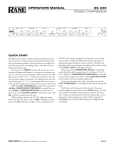
W
M.T
O
.C
W
00Y
1
M.T
.
O
W
WW .100Y.C M.TW
O
W
W
WW .100Y.C M.TW
NEW
E3X-ZD series
T
.
M
O
W
.CO .TW
Y
WW .100Y.C M.TW
0
0
O
W
OM
W.1
WW .100Y.C M.TW
WW .100Y.C M.TW
O
W
O
W
WW .100Y.C M.TW
W
WW .100Y.C M.TW
T
.
O
W
M
WW 00Y.CO .TW
.CO .TW
WW .100Y.C M.TW
Y
W
0
0
M
.1
WW 00Y.CO .TW
W.1 Y.COM W
WW 00Y.CO .TW
W
W
M
.1
.T
00
W.1 Y.COM W
WW 00Y.CO .TW
W.1 Y.COM W
W
W
W
.T
00
W.1 Y.COM W
M.T
.100
W.1 Y.COM W
O
W
W
W
C
.
W
W
.T
W
00
Y
W
M.T
.100
W.1 Y.COM W
M.T
.100
O
W
O
W
W
C
.
W
W
Y
W
.T
W
WW .100Y.C M.TW
.100
M.T
.100
OM
W
O
W
C
.
O
W
W
C
W
Y
W
WW .100Y.
.TW
WW .100Y.C M.TW
M.T
.100
M
O
W
O
W
C
O
W
WW .100Y.
.TW
WW .100Y.C M.TW
WW .100Y.C M.TW
M
O
W
O
W
O
W
WW .100Y.C M.TW
WW .100Y.C M.TW
WW .100Y.C M.TW
O
WW 00Y.CO .TW
W
WW 00Y.CO .TW
C
.
W
W
W
Y
W
W
M
.1
.T
00
W.1 Y.COM W
WW 00Y.CO .TW
W.1 Y.COM W
W
W
W
W
.T
W
.100
W.1 Y.COM W
M.T
.100
OM
W
O
W
W
C
.
W
C
W
Y
W
.T
W
00
W
WW .100Y.
M.T
.100
W.1 Y.COM W
M.T
O
W
O
W
W
C
.
W
W
WW .100Y
WW .100Y.C M.TW
M.T
.100
M.T
O
W
O
W
C
.
O
W
W
W
Y
W
WW .100Y.C M.TW
WW .100Y.C M.TW
M.T
.100
O
W
O
W
C
O
W
WW .100Y.
.TW
WW .100Y.C M.TW
WW .100Y.C M.TW
M
O
W
O
W
O
W
WW .100Y.C M.TW
WW .100Y.C M.TW
WW .100Y.C M.TW
O
W
O
W
O
W
WW .100Y.C M.TW
WW .100Y.C M.TW
WW .100Y.C M.TW
O
W
O
W
O
W
WW .100Y.C M.TW
WW .100Y.C M.TW
WW .100Y.C M.TW
O
WW 00Y.CO .TW
W
WW 00Y.CO .TW
C
.
W
W
W
Y
W
W
M
.1
.T
00
W.1 Y.COM W
WW 00Y.CO .TW
W.1 Y.COM W
W
W
W
W
.T
00
W
W.1 Y.COM W
M.T
.100
W.1 Y.COM W
O
W
W
W
C
.
W
.T
W
00
W
WW .100Y
M.T
.100
W.1 Y.COM W
M.T
O
W
O
W
W
C
.
W
W
WW .100Y
WW .100Y.C M.TW
M.T
.100
M.T
O
W
O
W
C
.
O
W
W
W
Y
W
WW .100Y.C M.TW
WW .100Y.C M.TW
M.T
.100
O
W
O
W
C
O
W
WW .100Y.
.TW
WW .100Y.C M.TW
WW .100Y.C M.TW
M
O
W
O
W
O
W
WW .100Y.C M.TW
WW .100Y.C M.TW
WW .100Y.C M.TW
O
W
O
W
O
W
WW .100Y.C M.TW
WW .100Y.C M.TW
WW .100Y.C M.TW
O
W
O
W
O
W
WW .100Y.C M.TW
WW .100Y.C M.TW
WW .100Y.C M.TW
O
WW 00Y.CO .TW
W
WW 00Y.CO .TW
C
.
W
W
W
Y
W
W
M
.1
.T
00
W.1 Y.COM W
WW 00Y.CO .TW
W.1 Y.COM W
W
W
W
W
.T
00
W
W.1 Y.COM W
M.T
.100
W.1 Y.COM W
O
W
W
W
C
.
W
.T
W
00
W
WW .100Y
M.T
.100
W.1 Y.COM W
M.T
O
W
O
W
W
C
.
W
W
Y
W
.T
W
WW .100Y.C M.TW
.100
M.T
.100
OM
W
O
W
C
.
O
W
W
C
Y
W
WW .100Y.
.TW
WW .100Y.C M.TW
M.T
.100
M
O
W
O
W
C
O
W
WW .100Y.
WW .100Y.C M.TW
WW .100Y.C M.TW
W
O
W
O
W
WW
WW .100Y.C M.TW
WW .100Y.C M.TW
O
W
O
W
WW .100Y.C M.TW
WW .100Y.C M.TW
O
W
O
W
WW .100Y.C
WW .100Y.C M.TW
W
O
W
WW
WW .100Y.C M.TW
O
W
WW .100Y.C M.TW
O
W
WW .100Y.C
W
WW
Digital optical fiber sensor
W
M.T
O
.C
W
00Y
1
M.T
.
O
W
WW .100Y.C M.TW
O
W
W
WW .100Y.C M.TW
T
Easy Operation for
Anyone
.
M
O
W
.CO .TW
Y
WW .100Y.C M.TW
0
0
O
W
OM
W.1
WW .100Y.C M.TW
WW .100Y.C M.TW
O
W
O
W
WW .100Y.C M.TW
W
WW .100Y.C M.TW
T
.
O
W
M
WW 00Y.CO .TW
.CO .TW
WW .100Y.C M.TW
Y
W
0
0
M
.1
WW 00Y.CO .TW
W.1 Y.COM W
WW 00Y.CO .TW
W
W
M
.1
.T
00
W.1 Y.COM W
WW 00Y.CO .TW
W.1 Y.COM W
W
W
W
.T
00
W.1 Y.COM W
M.T
.100
W.1 Y.COM W
O
W
W
W
C
.
W
W
.T
W
00
Y
W
M.T
.100
W.1 Y.COM W
M.T
.100
O
W
O
W
W
C
.
W
W
Y
W
.T
W
WW .100Y.C M.TW
.100
M.T
.100
OM
W
O
W
C
.
O
W
W
C
W
Y
W
WW .100Y.
.TW
WW .100Y.C M.TW
M.T
.100
M
O
W
O
W
C
O
W
WW .100Y.
.TW
WW .100Y.C M.TW
WW .100Y.C M.TW
M
O
W
O
W
O
W
WW .100Y.C M.TW
WW .100Y.C M.TW
WW .100Y.C M.TW
O
WW 00Y.CO .TW
W
WW 00Y.CO .TW
C
.
W
W
W
Y
W
W
M
.1
.T
00
W.1 Y.COM W
WW 00Y.CO .TW
W.1 Y.COM W
W
W
W
W
.T
W
.100
W.1 Y.COM W
M.T
.100
OM
W
O
W
W
C
.
W
C
W
Y
W
.T
W
00
W
WW .100Y.
M.T
.100
W.1 Y.COM W
M.T
O
W
O
W
W
C
.
W
W
WW .100Y
WW .100Y.C M.TW
M.T
.100
M.T
O
W
O
W
C
.
O
W
W
W
Y
W
WW .100Y.C M.TW
WW .100Y.C M.TW
M.T
.100
O
W
O
W
C
O
W
W
WW .100Y.
.TW
0Y.C M.TW
Y.C
0button
WW .100Independent
M
.TWteachingWfunction
1
.
O
W
M
O
W
O
W
WW .100Y.C M.TW
WW .100Y.C M.TW
WW .100Y.C M.TW
O
W
O
W
O
W
WW .100Y.C M.TW
WW .100Y.C M.TW
WW .100Y.C M.TW
O
W
W
O
W
.CO .TW
WW .100Y.C M.TW
W
W
setWkey .100Y
WW .100Y.C M.TExtra-large
M
O
WW 00Y.CO .TW
W
WW 00Y.CO .TW
C
.
W
W
W
Y
W
W
M
.1
.T
00
Pushbutton
W.1 Y.COM W
.CO .TW
WW 00Yoperation
W.1 Y.COM W
W
W
W
W
.T
00
W
.1
modeW
selector
OM
M.T
.100
W.1 Y.COM W
C
.
O
W
W
W
Y
W
C
.
W
W
(L-ON/D-ON)
.T
WW .100Y
M.T
.100
.TW
100
M
.
O
W
L-ON/D-ON
indicator
M
O
W
O
W
WW .100Y.C M.TW
WW .100Y.C M.TW
WW .100Y.C M.TW
O
WW 00Y.CO .TW
W
WW 00Y.CO .TW
C
.
W
W
W
Y
W
W
M
.1
.T
00
M
.1
WW 00Y.CO .TW
W.1 Y.COM W
WW 00Y.CO .TW
W
W
W
W
M
.1
.T
00
W.1 Y.COM W
WW 00Y.CO .TW
W.1 Y.COM W
W
W
W
W
.T
W
.100
W.1 Y.COM W
M.T
.100
OM
W
O
W
W
C
.
W
C
W
Y
W
.T
W
W
WW .100Y.
.100
M.T
.100
OM
W
M.T
O
W
C
.
O
W
W
C
W
Y
W
WW .100Y.
.TW
WW .100Y.C M.TW
M.T
.100
M
O
W
O
W
C
Teaching indicator
.
O
W
WW .100Y
.TW
WW .100Y.C M.TW
WW .100Y.C M.TW
M
O
W
O
W
O
W
WW .100Y.C M.TW
WW .100Y.C M.TW
WW .100Y.C M.TW
O
WW 00Y.CO .TW
W
WW 00Y.CO .TW
C
.
W
W
W
Y
W
W
.T
00
.1
W.1 Y.COM W
O/MThreshold displayWscreen
WBrightness
W.1 Y.COM W
C
.
W
W
Y
W
W
.T
W
.100
M.T
.100
OM
Lock leverW
W
M.T
.100
O
W
C
.
O
W
W
C
Y
W
WW .100Y.
.TW
WW .100Y.C M.TW
M.T
.100
M
O
W
O
W
C
O
W
WW .100Y.
WW .100Y.C M.TW
WW .100Y.C M.TW
W
O
W
O
W
W
Y.C
WW
0
WW indicator
T
.
0
WW .100Y.C M.TW Operation
M
.1
O
W
WW 00Y.CO .TW
C
.
W
W
Y
W
W
.T
00
W.1 Y.COM
W.1 Y.COM W
W
W
W
W
.100
M.T
.100
W
O
W
W
C
W
W
WW .100Y.
M.T
O
W
WW .100Y.C M.TW
O
W
WW .100Y.C
W
2
WW
The simplest E3X-ZD series
Simple
Easy pushbuttons Design
Extra-large
display screen
NEW DESIGN
W
M.T
O
.C
W
00Y
1
M.T
.
O
W
WW .100Y.C M.TW
O
W
W manual.
WW .100Y.C M.TW
T
Set without using
the
.
M
O
W
.CO .TW
Y
WW .100Y.C M.TW
0
0
O
W
OM
W.1
WW .100Y.C M.TW
WW .100Y.C M.TW
O
W
O
W
WW .100Y.C M.TW
W
WW .100Y.C M.TW
T
.
O
W
M
WW 00Y.CO .TW
.CO .TW
WW .100Y.C M.TW
Y
W
0
0
M
.1
WW 00Y.CO .TW
W.1 Y.COM W
WW 00Y.CO .TW
W
W
M
.1
.T
00
W.1 Y.COM W
WW 00Y.CO .TW
W.1 Y.COM W
W
W
W
.T
00
.T
W.1 Y.COM W
M[Time-saving]
.100
W.1 Y.COM W
O
W
W
W
C
.
W
W
.T
W
00
Y
W
M.T
.100
W.1 Y.COM W
M.T
.100
O
W
O
W
W
C
.
W
W
Y
W
.T
W
WW .100Y.C M.TW
.100
M.T
.100
OM
W
O
W
C
.
O
W
W
C
W
Y
W
WW .100Y.
.TW
WW .100Y.C M.TW
M.T
.100
M
O
W
O
W
C
O
W
WW .100Y.
.TW
WW .100Y.C M.TW
WW .100Y.C M.TW
M
O
W
O
W
O
W
WW .100Y.C M.TW
W fibersǖWW .100Y.C M.TW
Y.Cfixing the
optical
WW .100After
T
.
O
W in theYpresence
OM
WW
W Press
.CO .ofTW
Y.C
Wonce
C
the
“Teach”
function button
the test object
and
another
.
0
W
W
.TW
W
0
0
Y
W
1
0
0
W
M
.
.T
1
0time
M
.
O
1
W
M
.
O
Wset up the threshold and to adjust the W
in C
of the test object
to
.C
W
. theOabsence
W maximum
.TW
W
00Y
WW .100Y.C M.TW
1
WW .1sensing
T
M
.
.
00Y for proper
O
brightness.
It
saves
the
users’
time
spent
on
making
adjustment.
W
O
W
OM
W
Woperation
W the new E3X-ZD
Y.C
WW and.100Y.C M.TW
figure
comparison ofW
the
procedures
between
0
Y.Cbelow is.TaW
T
.
0
0
WW The
1
0
M
O
W
.1 model.OM
O
W.
Wexisting
WW .100Y.C M.TW
WW .100Y.C M.TW
WW .100Y.C M.TW
O
WW 00Y.CO .TW
W
WW 00Y.CO .TW
C
.
W
W
W
Y
W
W
.T
00
Push the
W.1buttonY.COM W
W.1 Y.COM W
Wtwice
W.1 Y.COM W
W
W
W
.T
0
W
W
.100
M.T
.10
OM
W
M.T
.100
O
W
C
.
O
W
W
C
W
W
00Y
WW .100Y.
.TW
WW .100Y.C M.TW
M.T
.1Without
M
O
W
With
the
test
object
the
test
object
O
W
C
Brightness
Mode
W Model
.C
WThreshold
.CO
Existing
WW .100Y.
.TW
.TW
00Y
WW
M
.TW adjustmentW Settings
1
00Y Settings
M
.
O
1
W
M
.
O
W
WW .100Y.C M.TW
WW 00Y.CO .TW
WW .100Y.C M.TW
WNEW
1
OM
WW 00Y.CO .TW
W.
Brightness
Threshold
Mode
WW 00Y.CO .TW
C
.
W
W
F4Y.[E
W
Y
W
Settings.1
W
M
.1
00 Settings .T adjustment
OM
W
WW 00Y.CO .TW
W.1 Y.COM W
C
.
W
Brightness
W
Y
W
W
0
W
W
adjustment .10
M.Tof brightness
OM
The
The display
W.1of brightness
M.T
.100
Odisplay
W
C
.
O
W
W
C
W
.
Y
W
C
with
a
test
object
without
a
test
object
W
.
Y
W
W
.T
WW .100Y
M.T
.100
.TW
100
M
.
O
W
M
O
W
O
W
WW .100Y.C M.TW
WW .100Y.C M.TW
WW .100Y.C M.TW
O
WW 00Y.CO .TW
W
WW 00Y.CO .TW
C
.
W
W
W
Y
W
W
M
.1
.T
00
MThreshold settings completed.
.1
WW 00Y.CO .TW
W.1 Y.COM W
WW 00Y.CO .TW
W
W
W
W
M
.1
.T
00
W.1 Y.COM W
WW 00Y.CO .TW
W.1 Y.COM W
W
W
W
W
.T
W
[Task-saving]
.100
W.1 Y.COM W
M.T
.100
OM
W
O
W
W
C
.
W
C
W
Y
W
.T
W
W
WW .100Y.
.100
M.T
.100
OM
Set key
W
M.T
O
W
C
.
O
W
W
C
W
Y
W
WW .100Y.
.TW
WW .100Y.C M.TW
M.T
.100
M
O
W
O
W
C
.
O
W
.C
WW .100Y
.TW
WW .100Y.C M.TW
WW
TW
M
.adjustment
The large size set
key makes
00Ythreshold
O
1
W
M
.
O
W
O
W
WW .100Y.C M.TW
WW .100Y.C M.TW
much easier.
WW .100Y.C M.TW
O
WW 00Y.CO .TW
W
Old version
New
version
WW 00Y.CO .T
C
W
.
W
W
Y
W
The figure on the rightW
is aW
comparison
between
the
buttons
of
0
M
.1
.T
.10old
W.1 Y.COM W
E3X-ZD, the new version, and of
version.
OM
WW 00Y.CO .TW
Wthe
W
C
.
W
W
W
W
.T
00
W
M
.1
.T
00Y
W.1 Y.COM W
WW 00Y.CO .T
W.1 Y.COM W
W
W
W
W
.T
W
.100
W.1 Y.COM
M.T
.100
OM
W
O
W
W
C
.
W
[Trustful]
C
W
Y
W
W
W
WW .100Y.
.100
M.T
.100
W
M.T
O
W
O
W
W
C
W
WW .100Y.
.TW
WW .100Y.C M.TW
M
O
W
O
W
.C
WW Teaching
00Yindicator M.TW
0Y.C (L-ON
WW .10indicator
.TW
1
.
M
This newly installed operation mode
/D-ON)
W
WW 00Y.CO
.COyou to
W
Y
W
and the teaching status display
allow
learn
0
WWindicator
T
.
.1
.10
OM
WW
C
about the status at a glance. WW
.
W
Y
W
W
.T
00
L-ON/D-ON
W.1 Y.COM W
W
indicator
0
W
T
.
0
1
M
.
O
W
C
.
Display screen
WW .100Y
W
W
3
W
The major features of E3X-ZD
Independent teaching function button
Push the button twice to adjust both the teaching and sensitivity.
Extra-large set key
Large display screen + Status indicator
W
M.T
O
.C
W
00Y
1
M.T
.
O
W
C
W
WW .100Y.
Types
M.T
O
W
WW .100Y.C M.TW
.TW
Amplifier unit (main body)
M
WW 00Y.CO .TW
.CO .TW
Y
W
0
Model
0
M
.1
Shapes W.1
Connections WW
OM
.CO
C
W
.
Y
W
NPN
output
PNP output
W
0
Y
W
T
W
M.
.10
M.T
.100
O
W
O
W
C
.
WW .100Y
.TW
WW .100Y.C M.TW
M
.TW
O
W
M
O
W
Pre-wired models
E3X-ZD11
2M W
E3X-ZD41 2M
.C
O
WW .100Y
.T
W
Y.C
WW .100Y.C M.TW
T
M
.
O
100
W
O
W
OM
WW .100Y.C M.TW
W
Y.C
WW .100Y.C M.TW
0
T
.
0
O
W
W.1 Y.COM W
WW 00Y.CO .TW
WW .100Y.C M.TW
W
0
T
.
0
Connector
models*
M
.1
E3X-ZD8
O
WW 0E3X-ZD6
W.1 Y.COM W
W
Y.C
WW 00Y.CO .TW
0
W
T
.
W
1
M
.
.T
M
.1
.100
OM
WW 00Y.CO .TW
WW 00Y.CO .TW
W
WW 00Y.*CSuitable
W
W
1
simplified
M
.T Please use the followingW
.1 wiring connectors
Mconnectors:
.1
OM (each sold separately). WW.
.CO .TW
C
.
Y
W
W
.CO .Twiring
0
Y
W
WW 00YSimplified
W connectors
0
0 separately)
W (each
.T
.10sold
W.1 Y.COM W
M
.1
OM
W
O
W
W
C
.
W
C
W
0
Y
.T
W
W
Types
CableW
length .10Quantity
of M
conductors
Model
WW .100Y.
100
M.T
.Shapes
O
W
M.T
O
W
C
.
O
W
W
C
W
.
Y
W
WW .100Y
.TW
WW .100Y.C M.TW
M.T
.100
M
O
W
O
W
C
.
O
W
Master
E3X-CN11
.C connectors
WW .100Y 3-wire M.TW
WW .100Y.C M.TW
WW .100Y
.TW
O
W
M
O
W
O
W
WW .100Y.C M.TW
WW .100Y.C M.TW
WW .100Y.C M.TW
2m
O
WW 00Y.CO .TW
W
WW 00Y.CO .TW
C
.
W
W
W
Y
W
W
M
.1
.T
00
W.1 Y.COM W
.CO .TWE3X-CN12
OM
WW 01-wire
W.1 Slave-connectors
Y
W
C
.
0
W
W
W
0
Y
W
.T
0
W
M
.1
.T
00
W.1 Y.COM W
WW 00Y.CO .TW
W.1 Y.COM W
W
W
W
W
.T
W
.100
W.1 Y.COM W
M.T
.100
OM
W
O
W
W
C
.
W
C
W
.
Y
W
.T
W
W
16Yunits
can
be connected
WWUp to
.100
M.T
.100
OM
W
M.T
.100
O
W
C
.
O
W
W
C
W
Y
W
W communication WW .100Y.
.TW
WW .100Y.C M.TOptical
M.T
.100
M
O
W
O
W
C
.
O
W
WW .100Y
.TW
WW .100Y.C M.TW
WW .100Y.C M.TW
M
O
W
O
W
O
W
WW .100Y.C M.TW
WW .100Y.C M.TW
WW .100Y.C M.TW
O
WW 00Y.CO .TW
W
WW 00Y.CO .TW
C
.
W
W
W
Y
W
W
M
.1
.T
00
OM
W.1 Slave-connectors
WW 00Y.CO .TW
W.1 Y.COM W
C
.
W
W
Y
W
W
W
.T
W
Master
.100
W.1 Y.COM W
M.T
.100
OM
W
connectors
O
W
W
C
.
Pins
for
W
C
W
.
Y
W
Y power is supplied
W power supply
.T
WW .100The
M.T
.100
.TWvia
100
M
.
O
W
M
O
W
C
O the wiring is
W connector
WW .100Y.
.TW
WW .100Y.C M.TW
0Y.Cto 1and
WW .10limited
M
.TW
(additional
part)
O
W
M
O
W
O
W
WW .100Y.C M.TW
WW .100Y.C M.TW
WW .100Y.C M.TW
W
ONote:It can be mixed and used withW
WW 00Y.CO .TW
W
.CO .TW
other series (e.g., Y
E3X-DA).
C
.
W
W
W
0
Y
W
W
10
00
M
W.1 Y.COM W
M.T of different models
Oand
W.(the
O
W
W.1orderYfor
C
.
Precaution for making
connectors
main
body
the connector
are sold W
separately).
W
C
W
.
Y
W
W
.T
0
M.T
.100
.TW
100
0combinations
Please review W
the following
when
making the order:
M
.
O
1
W
M
.
O
W
C
.
O
W
.C
Y.Cseparately)
WW .100Y
.TW
WW (each
.TW
Amplifier
00sold
WW unit
M
.TWSuitable connectors
1
00Y
M
.
O
1
W
M
.
O
W
O
W
.C
NPN
WW .100Y.C M.TW
WW .Slave-connectors
.TW
00Y
0Y.C M.TWMaster connectors
WW .1PNP
1
0
M
O
E3X-ZD6
E3X-ZD8
O + E3X-CN11(3-wire)WWE3X-CN12
WW 00Y.CO .TW
W
.C(1-wire)
C
W
.
Y
W
W
W
0
Y
W
T
.
0
W
M
.1
.T
00
<Example of 5 sets>
W.1 Y.COM W
WW 00Y.CO .TW
W.1 Y.COM W
W
W
W
.T
00
W
.T connector W
00
(1 unit), Slave-connectors
W.1 Y.COM
W.1 Y.CO(4M W
Amplifier unit (5 units)
W
W.1 Y.CO+ M Master
W
W
W
units)
W
.T
W
M.T
.100
.TW
100
00
M
.
O
1
W
M
.
O
W
C
W
.CO .TW
WW .100Y.
.
WW .100Y.C M.TW
Accessories (each sold
WWseparately)
00Y
OM
1
W
M
.
O
W
C
.
O
W
W
C
Y
Metal fixing installation accessories
Rear
Y.
W
WWpedestal
.TW
WW .100Y.C M.TW
M
.100
100
M
.
W
O
W
O Quantity
WQuantity00Y.CO
W
Shapes
Model
Model
WShapes 00Y.C
C
W
.
W
W
W
Y
W
T
.
W
.1
.T
00
W.1 Y.COM W
WW
W.1 Y.COM W
W
W
W
W
.T
00
WE39-L143.100
M1.T
1
W.1 Y.COM PFP-M
O
W
W
C
W
.
W
0
W
T
.
0
WW .100Y
T
.
1
M
O
W.
OM
W
WW .100Y.C
WW .100Y.C M.TW
W
O
W
WW
WW .100Y.C M.TW
O
W
WW .100Y.C M.TW
O
W
WW .100Y.C
W
4
WW
W
M.T
O
.C
W
00Y
1
M.T
.
O
W
C
W
WW .100Y.
Rating / Performance
M.T
O
W
WW .100Y.C M.TW
.TW
Amplifier unit
M
WW 00Y.CO .TW
.CO .TW
Y
W
0
Item /Model
1
M
.E3X-ZD□
M
.10
W
O
W
.CO .TW
W
C
.
Y
Light source
W
W
0
Y
W
0
W
Red AIGALNN
(620nm)
.T
00
M
(emitted wavelength)
W.1 LED
W.1 Y.COM W
CO
.
W
Y
W
0
W
.TW
W
0
0
W
T
.
1 (P-P) 10%
0
Power
DC12~24V±10% .Ripple
max.
M
.Tsupply voltage
1
M
.
O
W
M
O
W
O
W (supply voltage
0Y.Cconsumption
WW24V with
.TW40mA max.)
W
0current
Y.C Power.consumption
WW .100Y.C 960mW
Tmax.
.
1
T
M
.
M
O
100
W
O
(current
W
OM consumption)
WW .100Y.C M.TW
W
Y.C
WW .100Y.C M.TW Open collector
0
T
.
output
PNP)
0
O
W (NPNYor.C
O Load current 50mA max.
W
OMoutput
W(Residual
W.1 Y.Control
C
.
W
C
voltage
1.5V max.)
W
0
Y
W
.TW
W
0
0
W
T
.
1
0
0
T
M
.
.
1
0
M
.
O
1
W
L-ON
and
D-ON
pushbutton
switch
M
.
O
W
.C
W
W
.CO time
W
00Yfor each M.TW
Y
WW .100Y.C M.TWAction•Reset:W
1
0
T
.
.
Response
200μs
maximum
0
O
W
.1
W
OM
.CO (With
W
WW .100Yor.CmanualMadjustment
WW 00Sensitivity
.TW
W
Y.C adjustment
WW .100YTeaching
T
or without workpiece/Automatic)
.
T
.
M
O
1
W
M
.
O
W
.C
O
W
Wprotection
output
reverse
W short-circuitWprotection,
Y.C protect,.T
WW 0Protection
00Y output polarity
0reverse
Y.C circuit.TW
WW Power
1
0
0
M.T
.
1
M
.
O
1
W
M
.
O
W
C
Digital
display
Light
power/Threshold
0
~
9999
W
W
Y.
.CO .TW
.TW
0Y.C M
WW .10L-ON/D-ON
.TW Teach modeW
100 mode
WW .1Indicator
M
.
00Y (Orange)
indicator,
indicator,
Operation
indicator
O
W
M
O
W
.C
W
W
.CO .TW
.TW
Yinterference
WW .100Y.C M.TWLight parallelW(5 sets)* .100Y
0
WW Mutual
M
0
O
1
W
.
O
W
OM
Wprevention
WW .100Y.C M.TW
W
Y.C
WW .100Y.C M.TW
0
WW Vibration
T
.
0
O
W
O
10 to 55Hz, .1.5mm
amplitude for 2h each
W.1 Y.COM W
Y.ZCdirections.TW
WW
W
Y C double
WW in X,.1Y,00and
0
W
T
.
0
0
WW resistance(destruction)
T
.
OM
W
M
.10
W.1 Y.CO2M W
C
.
O
W
Shock
W
W
Y
W
C
.
0
Wand Z directions
3.T
times each in X, Y,
W
WWresistance(destruction)
M.T
.10
.TW
100 500m/sOfor
00Y
M
.
O
1
W
M
.
W
C
W
W
.C
Y.
W max., Sunlight:
.CO .TW
WW 20,000lx
WW Incandescent
Ambient illumination
10,000lx
.T
100max. OM.T
00Y lamp:
WW
.
1
00Y
M
.
1
W
M
.
O Amplifiers: -25 ~ +55℃W
.C
O
W
W
WW Group
W (with no.1condensation)
00Y
0Y.ofC1 to 3M
WOperation:
TW
.
0
WW .100Y.C M.TW
M.T
1
.
O
Group
of
4
to
11
Amplifiers:
-25
~
+50℃
(with
no
condensation)
W
O
W
C
Wtemperature O
Ambient
Y.
Y.16CAmplifiers:
WW
.TW
Group of 0
120to
-25 ~ +45℃ (with
no condensation)
WW
.TW
100
WW .100Y.C M.TW
M
.
1
M
.
O
W
O ~ +70℃(with no condensation)
W Storage: -30
O
W
WW .100Y.C M.TW
W
Y.C
WW .100Y.C M.TW
0
WW humidity
T
.
0
Ambient
Operation
and
storage:
35~85%RH(with
no
condensation)
1
OM
WW 00Y.CO .TW
W.
WW 00Y.CO .TW
C
.
W
W
W
Y
W
W resistance
M
.1
Insulation
20MΩ minimum
(DC500V)
.T
00
OM
W.1 Y
WW 00Y.CO .TW
W.1 Y.COM W
C
.
W
W
W
W
W
Dielectric
50/60Hz
1min
.T
W strength
.T
00
.100 AC 1,000V
W.1 Y.COM W
OM
WIEC60529
W
W.1 Y.COM W
C
.
W
W
Degree of W
protection
IP50
(with
the
protective
cover)
Y
W
.T
00
W
W
00
M.T
.100
W.1 40gY.COM W
M.T Pre-wired models:
.1state)
O
W
O
W
W
C
Weight (packaged
Approx.
100g,
Simplified
wiring
plug-in
models:
Approx.
.
W
W
WW .100Y
WW .100Y.C M.TW
M.T
.100
M.T (PBT)
O
W
O
Case
Polybutylene
phthalate
W
C
.
O
W
W
W
Y
Y.C
W
Materials WW
Y.C
WW .100Polycarbonate
TW
.(PC)
M.T
.100
.TW
M
cover .100
O
W
M
O
W
C
.C
WW .100Y.
WW 00Y.CO .TW
.TW
WW .100Y
.TW
Accessories W
User Manual
M
M
O
1
W
M
.
O
W
O
WW .100Y.C M.TW
WW as close
* Please place theW
amplifiers
possible to each
interference
function.
Wother for the mutual
0Y.C M.TW
Yas.C
WW
0
0
T
.
1
0
.
W
WW 00Y.CO .TW
W.1 Y.COM W
CO
.
W
W
Y
W
W
0
W
T
Simplified wiring
.
0
W connectors
.T
00
W.1 Y.COM W
W.1 Y.COM W
W
W.1 Y.COM E3X-CN11
W
W
W
Item /Model
E3X-CN12
W
.T
W
M.T
.100
.TW
100
00
M
.
O
1
W
M
.
O
W
C
.
O
W
Rated current
WW .100Y
.TW
0Y.C M.TW
WW .102.5A
WW .100Y.C M.TW
M
O
W
O
Rated voltage
O
W
WW 50V
Y.C
WW .100Y.C M.TW
TW
.max.)
WW .100Y.C M.TW 20MΩW
100 and 100mA
M
.
max. (atW
DC20mV
Contact resistance
O
WW 00Y.CO .TW
W
.CO(wire.resistance
W and the 0connectors
C
W
.
Y
W
W
[Connected
to
the
amplifier
units
excluded)]
W
0
Y
W
T
W
M
.1
.T
00
.1
OM
WW 00Y.CO .TW
W.1 Y.COM 50 times
C
Plugging (destruction)
(connected toW
theW
amplifier units
and
the connectors)
.
W
Y
W
W
W
W
W
.100 (PBT)OM.T
W.1 Y.COM
M.T
.100
Housing
PolybutyleneW
phthalate
O
W
W
C
.
W
C
W
.
Y
W
W
Materials
W
W
.T
W
M.T
.100
.TPhosphor
100 alloy plating
00Y
M
.
Contact
bronze/Nickel-cadmium
(PC)
O
1
W
M
.
O
W
C
O
WW .100Y.
WW 00Y.CApprox.
.
WW .100Y.C MApprox.
.TW 25g
Weight (packaged state) W
55g
.TW
OM
1
W
M
.
O
W
C
.
O
W
W
C
Y
W
WW .100Y.
.TW
WW .100Y.C M.TW
M
.100
M
W
O
W
.CO
O
W
W
.C
Y
W
C
W
.
0
Y
W
W
W
0
0
Y
W
T
.
0
W
.1
.T
00
W.1 Y.COM W
WW
W.1 Y.COM W
W
W
W
W
.T
00
W
M.T
.100
W.1 Y.COM W
O
W
W
C
.
W
W
WW .100Y
M.T
.100
M.T
O
W
O
W
C
.
WW .100Y
WW .100Y.C M.TW
W
O
W
WW
WW .100Y.C M.TW
O
W
WW .100Y.C M.TW
O
W
WW .100Y.C
W
5
WW
W
M.T
O
.C
W
00Y
1
M.T
.
O
W
C
W
WW .100Y.
Output circuit diagrams
M.T
O
W
WW .100Y.C M.TW
TW
.
M
WStatus Y.CO
OperationO
Output circuit
Timing
chart WW
Model
.C
W
Y
.TW
0
Selector
mode
T
.
100
0
M
.
1
M
.
O
W
O
W
WW .100Y.C M.TW
WW .100Y.C M.TW
WW 00Y.CO .TW
WW 00Y.CO .TW
W
W
W
.T
.1 ON OM
L•ON
W.1 Y.COM W
WLight
OM
W
C
.
W
C
W
.
Y
W
(LIGHT
ON)100
W
Y
W
M.T
.
M.T
.100
O
100
W
M.T
O
W
C
.
O
W
W
.C
Y
W
.C
W
M.T
.100
.TW E3X-ZD11W W.100Y OM.TW
00Y
O
1
W
M
.
C
NPN
W
W
.C
W
.CO Output
WW .100Y.
M.T
.TWE3X-ZD6 W W.100Y OM.TW
00Y
O
1
W
M
.
O
W
WW .100Y.C M.TW
W
Y.C
WW .100Y.C M.TW
0
T
.
0
O
W
M
.1
.CO .TW
WW
D•ON
WW .100Y.C M.TW
WW 00Y.CO .TW
W
Dark ON .100Y
O
(DARK ON) W
M
.1
OM
W
WW .100Y.C M.TW
WW 00Y.CO .TW
WW .100Y.C M.TW
WW 00Y.CO .TW
W.1 Y.COM W
WW 00Y.CO .TW
W
W
W
W
M
.1
.T
00
W.1 Y.COM W
WW 00Y.CO .TW
W.1 Y.COM W
W
W
W
W
.T
00
W
W.1 Y.COM W
M.T
.100
W.1 Y.COM W
O
W
W
W
C
.
W
.T
W
00
W
WW .100Y
M.T L•ON
.100
W.1 Y.COM W
M.T
O
Light ON WW
O
W
W
C
.
(LIGHT
W ON) W
Y
W
WW .100Y.C M.TW
M.T
.100
M.T
.100
O
W
O
W
C
.
O
W
W
W
Y
.C
W
WW .100Y.C M.TW
WW .PNP
M.T
.100
.TW
00Y E3X-ZD41
O
1
W
M
O
W
C
W
.CO .TW
WW .100Y.
.TW
WW .100Y.C M.TW
WW Output
M
00YE3X-ZD8
O
1
W
M
.
O
W
O
W
WW .100Y.C M.TW
WW .100Y.C M.TW
WW .100Y.C M.TW
O
W
O D•ON
W
O
W
W
WW .100Y.C M.TW
WW .100Y.C (DARK
T
Dark ON
.
WW .100Y.C M.TW
O
W
OM ON)
W
O
W
WW .100Y.C M.TW
WW .100Y.C M.TW
WW .100Y.C M.TW
O
WW 00Y.CO .TW
W
WW 00Y.CO .TW
C
.
W
W
W
Y
W
W
M
.1
.T
00
W.1 Y.COM W
WW 00Y.CO .TW
W.1 Y.COM W
W
W
W
W
.T
00
W
W.1 Y.COM W
M.T
.100
W.1 Y.COM W
O
W
W
W
C
.
W
.T
W
00
W
WW .100Y
M.T
.100
W.1 Y.COM W
M.T
O
W
O
W
W
C
.
W
W
WW .100Y
WW .100Y.C M.TW
M.T
.100
M.T
O
W
O
W
C
.
O
W
W
W
Y
W
WW .100Y.C M.TW
WW .100Y.C M.TW
M.T
.100
O
W
O
W
C
O
W
WW .100Y.
.TW
WW .100Y.C M.TW
WW .100Y.C M.TW
M
O
W
O
W
O
W
WW .100Y.C M.TW
WW .100Y.C M.TW
WW .100Y.C M.TW
O
WW 00Y.CO .TW
W
WW 00Y.CO .TW
C
.
W
W
W
Y
W
W
M
.1
.T
00
W.1 Y.COM W
WW 00Y.CO .TW
W.1 Y.COM W
W
W
W
W
.T
W
.100
W.1 Y.COM W
M.T
.100
OM
W
O
W
W
C
.
W
C
W
Y
W
.T
W
00
W
WW .100Y.
M.T
.100
W.1 Y.COM W
M.T
O
W
O
W
W
C
.
W
WW .100Y
.TW
WW .100Y.C M.TW
M.T
.100
M
O
W
O
W
C
.
O
W
W
W
Y
W
WW .100Y.C M.TW
WW .100Y.C M.TW
M.T
.100
O
W
O
W
C
O
W
WW .100Y.
.TW
WW .100Y.C M.TW
WW .100Y.C M.TW
M
O
W
O
W
O
W
WW .100Y.C M.T
WW .100Y.C M.TW
WW .100Y.C M.TW
O
W
O
W
O
W
WW .100Y.C M.
WW .100Y.C M.TW
WW .100Y.C M.TW
O
W
O
W
O
W
WW .100Y.C M
WW .100Y.C M.TW
WW .100Y.C M.TW
O
WW 00Y.CO
W
WW 00Y.CO .TW
C
.
W
W
W
Y
W
W
.1
.T
00
W.1 Y.COM W
WW
W.1 Y.COM W
W
W
W
W
.T
00
W
M.T
.100
W.1 Y.COM W
O
W
W
C
.
W
W
WW .100Y
M.T
.100
M.T
O
W
O
W
C
.
WW .100Y
WW .100Y.C M.TW
W
O
W
WW
WW .100Y.C M.TW
O
W
WW .100Y.C M.TW
O
W
WW .100Y.C
W
6
WW
Incident
Interrupted
Operation indicator
(orange)
ON
OFF
Output transistor
ON
OFF
Load (relay, etc.)
Brown
Operation indicator
(orange)
Reset
Load
Brown-Black
Main
circuit
Incident
Interrupted
Operation indicator
(orange)
ON
OFF
Output transistor
ON
OFF
Load (relay, etc.)
Black
Control output
DC
12̚24V
Blue
Reset
Brown-Black
Incident
Interrupted
Operation indicator
(orange)
ON
OFF
Output transistor
ON
OFF
Load (relay, etc.)
Brown
Reset
Black-Blue
Operation
indicator
(orange)
Main
circuit
Black
Incident
Interrupted
Load
Blue
Operation indicator
(orange)
ON
OFF
Output transistor
ON
OFF
Load (relay, etc.)
Control output
Reset
Black-Blue
DC
12̚24V
W
M.T
O
.C
W
00Y
1
M.T
.
O
W
C
W
WW .100Y.
Dimensions
M.T
O
W
WW .100Y.C M.TW
.TW
Amplifier unit
M
WW 00Y.CO .TW
.CO .TW
Y
W
0
0
M
.1
Pre-wired models
W.1 Y.COM W
WW 00Y.CO Light
W
W
E3X-ZD11
W
.Tindicator
W
Mindicator
.1
Operation
M.T
.100
O
W
E3X-ZD41
O
W
C
.
WW .100Y
.TW
WW .100Y.C M.TW
M
.TW
O
W
M
O
W
O
WW .100Y.C M.TW
W
Y.C
WW .100Y.C M.TW
T
.
100
OM
WW 00Y.CO .TW
WW 00Y.CO .TW
C
.
W
W
Y
W
M
.1
.T
00
W.1 Y.COM W
WW 00Y.CO .TW
W.1 Y.COM W
W
W
W
.T
00
M
.1
.T
00
W.1 Y.COM W
WW 00Y.CO .TW
W.1 Y.COM W
W
W
W
.T
.100
W.1 Y.COM W
M.T
.100
OM
W
O
W
W
C
.
W
C
W
Y
W
W
.T
W
Y.
W
.100
M.T
.100
OM
W
M.T
.100
O
W
C
.
O
W
W
C
W
Y
.C
W
W
WW .100Y.
.TW
M.T
.100
.TW
00Y
M
O
1
W
M
.
O
W
C
O
W
WW .100Y.
.TW
WW .100Y.C M.TW
Metal fixing installation accessories
WW .100Y.C M.TW
M
O
(E39-L143) (each sold separately)
W
O
W
C
.
O
W
W
C
[Stainless
W steel (SUS304)]
.
Y
W
0
W
T
.
0
WW .100Y
T
.
1
WW .100Y.C M.TW
M
.
M
O
W
O
W
Connector C
models
O
W
0Y.C M.TW
WW Light
W
0indicator
Y.
WW .100Y.C M.TW
1
0
WW E3X-ZD6
T
.
.
0
Operation
O
Windicator
W.1 Y.COM W
WW 00Y.CO .TW
WW .100Y.C M.TW
W
0
WWE3X-ZD8
T
.
0
M
.1
WW 00Y.CO .TW
W.1 Y.COM W
WW 00Y.CO .TW
W
W
W
W
M
.1
.T
00
W.1 Y.COM W
WW 00Y.CO .TW
W.1 Y.COM W
W
W
W
0
W
.T
0
W
M
.1
.T
00
W.1 Y.COM W
WW 00Y.CO .TW
W.1 Y.COM W
W
W
W
W
.T
W
.100
W.1 Y.COM W
M.T
.100
OM
W
O
W
W
C
.
W
C
W
Y
W
.T
W
W
WW .100Y.
.100
M.T
.100
OM
W
M.T
O
W
C
.
O
W
W
C
W
Y
W
WW .100Y.
.TW
WW .100Y.C M.TW
M.T
.100
M
O
W
O
W
C
.
O
W
WW .100Y
.TW
WW .100Y.C M.TW
WW .100Y.C M.TW
M
O
W
Note:
The
installation
method
is
equal
to
pre-wired
model.
O
W
O
W
WW .100Y.C M.TW
WW .100Y.C M.TW
WW .100Y.C M.TW
O
WW 00Y.CO .TW
W
WW 00Y.CO .TW
C
.
W
W
W
Y
W
W wiring.1connector
Simplified
units
M
.1
.T
00
W.1 Y.COM W
OM
WW 00Y.CO .TW
W
W
C
.
W
W
W
Y
W
.T
Female connectors
00
W
.T
W.1 Y.COM W
.100
OM
W.1 Y.
OM W
C
E3X-CN11 WW
W
C
W
.
W
W
.T
00
W
M.T
.100
.TW 1Vinyl-insulated
00Y
M
.
O
1
W
M
.
O
round
cable
of
4
dia.,
3
cores
W
C
O
W
.C
WW .100Y.
with 1.1-dia. insulator)
.TW
WW (0.2
.TW
0mm0Y
WW .100Y.C M.TW
M
1
M
.
O
W
O
φ
W
O
W
WW .100Y.C M.TW
WW .100Y.C M.TW
WW .100Y.C M.TW
O
WW 00Y.CO .TW
W
WW 00Y.CO .TW
C
.
W
W
W
Y
W
W
M
.1
.T
00
W.1 Y.COM W
WW 00Y.CO .TW
W.1 Y.COM W W
W
W
W
.T
W
.100
W.1 Y.COM W
M.T
.100
OM
W
O
W
W
C
.
W
C
W
Y
W
.T
W
00
W
WW .100Y.
M.T
.100
W.1 Y.COM W
M.T
O
W
O
W
W
C
.
Sub-connectors
W
WW .100Y
.TW
WW .100Y.C
M.T
.100
.TW
M
O
W
E3X-CN12
M
O
W
C
.
O
W
W
W
Y
.C
Y.C
W
Vinyl-insulated
of 2.6 dia., 1 .core
WW round
TW
WW .1
M.T
.100
.TW
100cable
00Y
.
O
W
(0.2 mm with
1.1-dia.
insulator) OM
M
W
C
O
W
WW .100Y.
.TW
WW .100Y.C φM.TW
WW .100Y.C M.TW
M
O
W
O
W
O
W
WW .100Y.C M.T
WW .100Y.C M.TW
WW .100Y.C M.TW
O
W
O
W
O
W
WW .100Y.C M.
WW .100Y.C M.TW
WW .100Y.C M.TW
O
W
O
W
O
W WW .100Y.C M
WW .100Y.C M.TW
WW .100 Y.C M.
TW
O
WW 00Y.CO
W
WW 00Y.CO .TW
C
.
W
W
W
Y
W
W
.1
.T
00
W.1 Y.COM W
WW
W.1 Y.COM W
W
W
W
W
.T
00
W
M.T
.100
W.1 Y.COM W
O
W
W
C
.
W
W
WW .100Y
M.T
.100
M.T
O
W
O
W
C
.
WW .100Y
WW .100Y.C M.TW
W
O
W
WW
WW .100Y.C M.TW
O
W
WW .100Y.C M.TW
O
W
WW .100Y.C
W
7
WW
/
Rear pedestal
(each sold separately)
PFP-M
No. of additional unit
L(mm)
Indicator window
(for mutual interference prevention)
Two, 3.2 dia. Holes
/
φ
Rear pedestal
(each sold separately)
PFP-M
No. of additional unit
L(mm)
Indicator window
(for mutual interference prevention)
2
f
f
2
f
f
W
M.T
O
.C
W
00Y
1
M.T
.
O
W
C
W
WW .100Y.
Optical fiber types
M.T
O
W
WW .100Y.C M.TW
.TW
Reflective Through-beam
M
WW 00Y.CO .TW
.CO .TW
* Use amplifier unit E3X-ZD
Y
W
0
1
0
M
.
1
M
.
O
W
O
W
.C BendingWradius
Sensing distance W Minimum
sensing
.C
Y
Types
Shapes(mm)*3
Feature
Model
WW
.TW (mm)*1 W W
100(mm)*2OM.T(mm)
00Y
.
1
object
M
.
O
W
C
.
W
C
W
.
Y
W
W
Y
W
.T
W
00
W
M.T
.100
W.1 Y.COM W M6 screws E32-DC200
M.T
O
W
O
W
C
.
W
W
W
Y.C
WW .1000Y
M.T
.100
M.T
O
100
W
M.T
O
W
C
.
O
W
W
Y
.C
Y.C
W
WW .
.TW
M.T M6 screws E32-DC200B
.100
.TW
100
00Y
M
O
1
W
M
.
O
W
C
W
W
.CO .TWDimensions Do notW
Y.C
WW .100Y.
.TWwith tubes E32-DC200B4
bent the tube. 0 φ 00
.TW
M
1
00Y
M
.
for
O
1
W
M
.
O
W
WW 00Y.CO .TW
WW .100Y.C R25M.TW
WStandard
3 dia.
Y.C
W
0
T
.
1
0
E32-D12
M
.
Model
O
W
M
.1
O
W
C
columns
.
O
W
W
C
W
.
Y
W
C
W
.
0
Y
W
T
W
φ
.
W
0
0
Y
W
T
.
M
.1
.10
(φ0.005)
M.T
.100 Standards
OM
φ WW
WW 00Y.CO 6.Tdia.W
C
.
W
Y
W
WW 00Y.CO .TW
W
.100 OM.T
E32-D14L
W.1 Y.COMcolumns
M
.1
W
O
W
W
C
W
.
W
C
W
.
0
Y
W
T
W
(Side
View)
.
W
0
0
Y
W
T
.
0
W
M
.1
.T
00
W.1 Y.COM W
WW 00Y.CO .TW
W.1 Y.COM W
W
W
W
W
.T
00
W
Mscrews E32-DC200E
W.1 Y.COM3
M.T
.100
W.1 Y.COM W
O
W
W
(small)
W
W
C
Dimensions
.
0
W
W0
.T
WW .100Y
M.T
.10R10
.TW
100
for
small
M
.
O
W
M
O
W
O
W
screws W
W
Y.C
WW .100Y.CM3
W
.TW
WW .100Y.C model
.100
M.T E32-DC200F
(small)
.TW
M
O
W
M
O
W
C
.
O
W
W
Do not bent the tube R5 0 φ W
Y with tubes.TW
Y.C
W
W
.TW
WW .100Y.C M.TW
M
.100
100
M
.
W
O
Dimensions
W
.CO
O
W
W
C
W
.
Y
W
C
W
.
0
Y
W
W
M6
screws
for
standard
.TE32-D11
W
0
0
Y
W .10
.T
1
W
M
.
00 modelM.T
M
O
1
W
.
O
W
0
O
W
WW .100Y.C M.TW
WW .100Y.C M.TW
WW .100Y.C M.TW
screws
O E32-D21B
O
WW 0M4
W
Y.C
WW 00Y.CO .TW
C
.
0
W
W
(small)
.TW
W
Y
W
1
0
W Bent-resistant
T
M
.
.
0
1
0
M
.
O
1
W
M
.
W
Y.C
WW 00Y.CO .TW
.CO .TW
WW
M3
R4
.TW
00screws
W
1
0forYsmall
WW .10Dimensions
M
.
E32-D21
1
M
.
O
W
M
O
(small)
W
C
.
O
W
WW .100Y
.TW
WW .100Y.C M.TW
0Y.C M.TW 0
WW .10model
M
O
1.5
dia.
W
O
W
O
W
.C
Y.C E32-D22B
WW columns
.TW
WW
.TW
100
00Y
WW .100Y.C M.TW
M
.
1
M
.
φ
O
W
O
W
.C
O
W
W
WW (small)
00Y
WW .100Y.C M.TW
1
WW .100Y.C M.TW
M.T
.
O
W
O
W
C
O
W
W
R25 WWM6 screws0Y.E32-D11L
.C
.TW
W
.TW
10
00Y
WW .100Y.C 0M.TW
M
.
1
M
.
O
W
O
Long
W
O
W
WW .100Y.C M.TW
WW .100Y.C (φ0.005)
.TW
distance
W/W .100Y.C M.TW
M
O
M4 screws
E32-D21L
W
High
WW 00Y.CO .TW
WW .100Y.C M.TW
WW 00Y.C0O .TW
W
W
performance
R10
OM
W.1
OM
WW 00Y.CO .TW
W.1
3 dia.
W
WW .100Y.C M.TW
WW .100Y.C M.TW
M
W.1 E32-D22L
columns
O
W
.CO .TW
O
W
W
C
.
Y
W
C
φ
W
.
0
Y
W
W
W
0
0
Y
W
T
.
0
W
M
.1
.T
00
W.1 Y.COM W
.CO .TW
0.8 dia.WW
W.1 Y.COM W
Y
W
0
W
W
E32-D33
0
W
.T
0
W
tubes
.100
h e t.u1
b e0
. φ φ
W.1 Y.COM W
M.T
Ultra-compact/ D o n o t b e n t tW
OM
W
O
W
C
.
W
R4
C
W
Y
W
.T
W
With thin tube
WW .100Y.
.100
.TW
M.T
.100
OM
0.5 dia.
W
M
O
W
C
.
O
W
W
E32-D331
C
.
W
.TW
φ φ
W
00Y
Y.C
WW .100Y
TW tubes W
.
1
T
M
.
.
Do notW
bent the tube. 100
M
O
W
M
.
O
W
.C
W
W
WW 00Y.CO .TW
00Y
WW .100Y.C M.TW M4 W
1
W
M.T
.
Flexible Dimensions
O
1
W
M
.
for standard
O
rectangular
E32-D11N
W
C
O W
W
Y.
(New standard) model
.TW
WW .100Y.C MR1.TW screws W
100
WW .0100Y.C M.TW
M
.
O
W
O
W
O
W
WW .100Y.C M.T
WW .100Y.C M.TW
WW .100Y.C M.TW
O
W
O
W
O
W
WW .100Y.C M.
WW .100Y.C M.TW
WW .100Y.C M.TW
O
W
O
W
O
W
WW .100Y.C M
WW .100Y.C M.TW
WW .100Y.C M.TW
O
WW 00Y.CO
W
WW 00Y.CO .TW
C
.
W
W
W
Y
W
W
.1
.T
00
W.1 Y.COM W
WW
W.1 Y.COM W
W
W
W
W
.T
00
W
M.T
.100
W.1 Y.COM W
O
W
W
C
.
W
W
WW .100Y
M.T
.100
M.T
O
W
O
W
C
.
WW .100Y
WW .100Y.C M.TW
W
O
W
WW
WW .100Y.C M.TW
O
W
WW .100Y.C M.TW
O
W
WW .100Y.C
W
8
WW
Dimensions
in “()” are for B4
Dimensions
in “()” are for F4
W
M.T
O
.C
W
00Y
1
M.T
.
O
W
C
W
WW .100Y.
M.T
O
W
W
WW .100Y.C M.TW
.T
Sensing
distance
Minimum
radius
M
W sensing
Types
Shapes(mm)*3 .CO
Model
.COBending
Wobject
W Feature
Y
W
(mm)*1
(mm)*2
(mm)
0
Y
W
T
.
0
0
T
.
1
0
M
.
1
OM
W.
WW 00Y.CO .TW
W
W
WW .100Y.C M
T
.
W.1 Y.COM WM6 screws E32-DC200
O W0
W
C
.
W
W
Y
W
R25 .T
W
00
W
M.T
.100
W.1 Y.COM W
M.T
O
W
M3 screws
O
W
C
.
E32-C31
W
.T (small)
W
00
Y.C
WW 0 .100Y M.TW
1
T
M
.
.
O
100
W
M
O
W
C
.
O
W
W
Y
.C
W
WW .100Y.C M.TW
M.TM3
.100
.TW
00Y
O
1
W
M
.
O
W
C
W
E32-C31N
.CO
Y.C
WW .100Y. R4 M.rectangular
TW
WW .100
.TW
0
00Y CoaxialM/ .TW
screws
M
O
1
W
.
W
O
W
.CO .TW
WW .100Y.C MSmall
.TW
W
Y.C
WW .1060~Y15mm
E32-D32
0
T
Small
.
0
M
O
1
W
M
.
O
(φ0.005)
W
+
C
luminousW
spot
.
O
W
W
C
.
luminous
Y
W
Spot
dia
φ0.5
~
1mm
C
W
.
0
Y
W
T
W
.
E39-F3A
W
0
0
Yspot
W
T
.
1
0
0
T
M
(variable)
.
.
1
0
O
W
M
.1
OM
W.
W E32-C31
W
Y.C
WW .100Y.C Small
WW 00Y.CO .TW
0
WW 7mm
T
.
0
M.T
1
+
M
.
luminous
O
1
W
M
.
O
W
C
. spot .TW E39-F3A-5
O
φ0.5mm
W
W
.C
Y
W Spot dia
C
W
.
0
Y
W
W
W
0
0
Y
W
T
R25
.
W
.1
.T
00
.10
OM
OM
distance / W
W
E32-C31
WW 00Y.CLong
W.1 Y.COM W
C
.
W
17mm
W
Y
W
W
.T +
0
W
T
.
Small
1
0
0
W
T
M
.
.
1
0
M
.
O
1
Spot
dia
φ0.5mm
W
O
W
C spot TE39-F3B
OM
W.
W
WW .100Y.luminous
WW .100Y.C M.TW
WW .100Y.C M.TW
M./ E32-C31
O
W
Long
distance
O
W
0
~
20mm
.C
O
W
W
.C
+
WW .100Y
WW
Parallel lightM.T
00Ymax. M.TW
WW .100Y.C M.TW
Spot dia .φ4mm
1
E39-F3C
O
W
O
W
C
.
O
W
W
Y
W
.TW
WW .100Y.C M.TW
WW .100Y.C M.TW
ME32-TC200
.100M4 screws
O
W
O
W
C
O
W
WW .100Y.
.TW
WW .100Y.C M.TW
0
0Y.C
WW .10Dimensions
TW
M
O
W
for standard OM.
O
W
.C
W
W
WW .31dia.
00Y
WW .100Y.C M.TW
0Y.C Mφ.TW
WW .10model
M.T
O
W
columns
E32-T14L
O
W
C
R25
φ1(φ0.005)
O
W
W
Y.
WW (Side
WW .100Y.C M.TW
100View) OM.T
WW .100Y.C M.TW
.
W
O
W
O
W
WW .100Y.C M.TW
WW .100Y.C M.TW
WW .100Y.C M.TW
M3 screws
Standards
O
W
C
E32-TC200A
O
WW
W
.CO .TW
W
C
(small) 00Y.
.
Y
W
W
.TW
W
0
Y
W
1
0
0
W
M
.
.T
1
00
M
.
O
1
W
M
.
O
W
.C
O
W
Dimensions
WWM3 screws
.TW
W
00YE32-TC200E
Y.C
WW .100Y.C M.TW
1
0
WW for small
T
M
.
.
0
O
1
W
O
W
(small)
.C
OM
W
W.
W
model
0
Y.C
W
00Y
WW .100φ0.5(φ0.005)
TW R10 W
.
1
WW .100Y.C
T
M.T
.
.
M
O
W
M
2
dia.
O
W
O
W
W
0Y.C M.TW
W
WW .100Y.C M.TW
columns .10E32-T22
WW .100Y.C M.TW O
W
φ
O
(small)
W
W
W
Y.C
WW 00Y.CO .TW
C
.
0
W
W
W
0
Y
W
W
M.T
.1
.T
1
Dimensions .100
M
.
O
W
M
O
W
C
W E32-T11
for standard
M4W
screws
.C
Y.
φ1(φ0.005)
WW
WW 00Y.CO .TW
.TW
.TW
100
00Y
W
model
M
.
1
M
.
0
O
1
W
M
.
O
W
WW .100Y.C M.TW
WW 00Y.CO .TW
WW .100Y.C M.TW
M3 screws
Bent-resistant W
E32-T21 .CO
W
.1
OM DimensionsWW
(small)WW
Y
WW 00Y.CO .TR4
C
W
.
.TW
W
Y
W
0
100
W
M
.
for small
.T
1
00
φ0.5(φ0.005)
M
.
O
1
W
M
.
O
W
.C
O
dia. columns
model WW
W
WWE32-T22B
W
00Y
Y.C
WW .100Y.C M.TW 1.5
1
0
W
T
M.T
.
.
0
(small)
O
1
W
M
.
O
W
C
φ
.
O
W
WW .100Y
.TW
WW .100Y.C M.TW
WW .100Y.C M.TW
M
O
W
O
W
M4 screws E32-T11L
O
W
WW .100Y.C M.TW
WW .100Y.C M.TW
WWM4 .100Y.C M.TW
R25
φ1.4(φ0.01)
O
WW 00Y.CO .TW
W
WW 00Y.CO .TW3 dia.
C
.
W
W
W
Y
W
W
M
Long
.1
E32-T12L
.T
.100
columns
W.1 Y.COM W
OM
WW 00Y.CO .TW
φ3WW
W
distance /
C
.
W
W
Y
W
.T
00
W
High
W.1 Y.COM
M.T
.100
W.1 Y.COM M3Wscrews E32-T21L
O
W
W
W
C
.
W
W
performance
W
.T
(small)
W
M.T
.100
.TW
100
00Y
M
.
M3
O
1
W
M
.
O
W
C
O
W
C
φ0.9(φ0.005)
W
WW .100Y.
.
WW .100Y.R10
WW .100Y.C M.TW
2.T
dia. columns
M
OM
W
E32-T22L
O
W
C
.
O
W
W
C
Y
(small)W
.C
W
W
WW .100Y.
.T
φ2 W
.100
.TW
00Y
M
OM
1
W
M
.
O
W
O
W
W
.C M4 .TW
Y.C
W
C
.
0
Y
W
W
W
0
0
Flexible Dimensions
Y
W
0
W
for standard
E32-T11N
M
φ1(φ0.005)
W.1
.100 OM.T
W.1 Y.COrectangular
(New standard) model
W
W
W
C
W
.
screws
W
W
W
0
W
.T
0R10
W
00Y
M.T
.1paper.
W.1 Y.COM W
*1. The sensing distance is measured by using white drawing
O
W
W
C
.
W
Y
W state.in10the0standard modeM(typical).
.T
WWwhen setting
*2. The value of minimum sensing object is measured
M.Tand sensitivity at the optimal
.100the sensingOdistance
O
W
W
C
*3. The models with
are free-cutting.
.
WW .100Y
WW .100Y.C M.TW
Note:Check our website for more detailed dimensions.
W
O
W
Flexible
Bent-resistant
WW
WW .100Y.C M.TW
O
W
WW .100Y.C M.TW
O
W
WW .100Y.C
W
9
WW
Coaxial
Coaxial
Coaxial
4 dia. luminous spot
v
W
M.T
O
.C
W
00Y
1
M.T
.
O
W
C
W
WW .100Y.
Correct usage
M.T
O
W
.C
W
WW .1Joining
00Y Amplifier
.TW
M.TUnits (for Units with Connectors)
M
O
W
Precautions for.C
Correct
Use
O
C
W
Y.Units can be
Y
WW Up
.Tjoined.
0to016
.TW
1Mount
00following
M
.
1
1.
the ampliefier
unit onto the DIN track.
M
.
Do not install the products
at
the
locations:
O
W
O
W
W
.C
Y.C
amplifier unit
and then insert it into the connector until you
W
•In the place exposed
0the
Ysunlight.
WW 2. .Slide
T
.
0
0
WWto the.direct
T
.
1
0
1is high and O
M
hear a click. COM
•In the place where humidity
condensation
may occur.
W
W
.
W
Y.C
WW .100Y
•In
gas
.TW
Wthe place where
Wcorrosive
.TW
00exists.
M
.T
1
M
.
O
W
M
•In
the
place
where
vibration
or
shock
is
directly
transmitted
to
the
product.
O
W
W
W .C
Y.C
W
W
.CO If the
0
Y
W
T
.
W
0
0
Y
W
T
.
power
lines
and
the
photoeletric
switch
share
the
same
wiring
1
0
0
T
M
.
.
M
10
W.1 or
OM
casing or wiring slot, product
due to
WW 00Y.CO .TW
CO canThappen
.damage
Wmalfunction
C
W
.
Y
W
W
0
Y
W
.
0the wiring or M
induction.
use a shielded line.
M
.1
.T In principle, please separate
00
O
W.1a cableYthat
WW 00Y.CO .TW
W.1 Y.COForMextending
C
.
W
the cable, please
adopt
is
at
least
0.3mm
and
W
W
W
W
.T
.T
100
00
W.1 Y.COM W
OM
OMthe length to 100m or less.WW.
W
W.1 Y.Climit
C
.
W
Y
W
turning
the power, W
wait for at least00
200ms before conducting
.T
M.T
.100
.TWon
1product
00 After
M
.
O
1
W
M
.
O
W
the
detection.
If
the
power
supply
for
the
and
the
electric
load
C
.C
COseparated,
WW .100Y.
WW 00Y.are
.TW
WonWthe power
make sure to turn
first.
.TW
00ofYthe product
M
.TW
1
M
.
O
1
W
M
.
O so make
W off Y
generated when
the.C
power,
W
Y.C the connection.
Wturning
.CO pulses.Twill
WW
WW 00YOutput
Wbe
00discnnoect
0line
Wload
TW
.
Note:For vibration.may
1
0
M.T Please use the optional installation
1
sure
that
the
power
of
the
electric
or
the
load
is
turned
off
first.
M
.
O
1
W
M
.
O
W
accessory
(PFP-M)
for
securing.
C
.
W
W
.COto prevent
0Y
Y.Cusing the.TW
WW
.TW
Weletric shock orWshort-circuited
Please
remove it.1
in0the
reverse sequence.
0when
Yorder
0power
WW .100In
M
.Tplease
1
M
.
O
W
M
connector
type,
put
a
protector
seal
on
the
terminals
that
Make
sure
that
the
amplifier
unit
should
be removed before DIN track is removed.
O
W
O
W
W
.Cseries) .TW
Y.C
W
0
Y
W
.TW
(connector:
provided
with
the
E3X-CN
W
0
0
W
1
0
0Ynot.Cconnected
WW .10are
T
M
.
.
1
M
.
O
W
O
W
Note: 1.When the
number
can be applied
OM
Wunits are connected,
W
Wof connection
Y.Cdifferent
.T"rating
00Please
WW .100Y.C M.TW
forW
different conditions.
comfirm
the
/ performance".
1
WW .100Y.C M.TW
M
.
Wthe power before O
2.Always turn
off
connecting or disconnecting.
O
W
O
W
WW .100Y.C M.TW
WW .100Y.C M.TW
WW .100Y.C M.TW
O
O
WW 0wiring
W
W
Y.C connector
WW 00Y.CO .TW
C
.
0
W
W
Simplified
W
Y
W
W
M.T units
.1
.T
1
00
M
.
O
1
W
M
.
O
W
C
O
W
Mounting Units
WW .100Y.
.TW
WWseal .100Y.C M.TW
WW .100Y.C M.TW
Protector
M
O
W
①When
connecting
the
female
connector
to
the
sub-connector of a
O
W please insert
W
W
Yit.Cin the connector
WW 00Y.CO .TWsingle amplifierWunit,
C
.
0
W
.
W
0
Y
W
1
0
W
M T until you hear a
.
.T
1
0
M
.
O
1
W
M
.
O
click.
W
C
supply connector
W
.C
.CO .Power
WW .100Y.
.TW
WWseparating
.TW
00orY
0Ythe
WW
TWis turned off before
M
Make sure
powerM
supply
1
0that
M
.
O
1
W
.
O
W
O
Wamplifiers.
adding
WW .100Y.C M.TW
W
Y.C
WW .100Y.C M.TW
0
WDoWnot peform
T
.
0
1
or compression when the
optical
. product expansion
OM units.
WW 00Y.CO .TW
Wfixed
WW 00Y.CO .TW
C
.
W
W
fibers
are
at
the
amplifier
W
Y
W
0
W
.T
1
W.1 Y.COM W
.10the
OM
W.the
Make sure
protection
OMcover is in place when operating
W
Wthat
C
.
W
C
W
.
0
Y
W
W
W
.T
product.
W
M.T
.10Insert
.TW
100
00Y
M
.
O
1
W
M
.
O
W
C
.
O
W the sub-connector
W benzene, acetone, or kerosene for cleaningWthe product.0Y.C ②Once theW
W
Do not use
thinners,
female connector
well
Wand
.Tconnected,
00Y areM
W
.Tconnect
WW .100Y.C M.TW
.1unit.
10
please
them to the amplifier
M
.
O
W
O
W
O
W
Y.C side.of
the accessory label
on the non-connection
the
W
WW
TW
WW .100Y.C③Please
Tand
.put
100
WW .100Y.C Settings
M
.
.TW
femalethe
sub-connectors.
M
O
W
M
O
W
C
.
O
W
W
W
Y
.C
W
W
WW .100Y.C M.TW
Amplifier
Wunit
M.T
.100
.TW
00Y
O
1
W
M
.
O
W
C
W
Mounting Units
.CO .TW
WW .100Y.
.TW
WW .100Y.C M.TW
0Yclaw
WW .10the
M
O
W
M
Fit the track by inserting
of
the
side
of
the
optional
fibers
unit
O
W
.CO it.Tlocked
WW .100Y.C M.TW
WW
W in to place.WW .100Y.C M.TW
insertion and
pressing the
Yhooks,until
0
Wthen
0
WW 00Y.CO .TW
W.1 Y.COM W
WW 00Y.CO .TW
W
W
W
W
.T
00
W.1 Y.COM W
W.1 Y.COM WSeal
WSeal
W.1 Y.COM W
W
W
W
0
W
.T
W
M.T
.100
.T
10Note:Please
00
M
.
put
the Seal on the slot side.
O
1
W
M
.
O
W
C
.
O
W
.C
WW .100Y
.TW
WW Removing
00Y UnitsM.TW
WW .100Y.C M.TW
M
1
.
O
W
O
W
O
W
C
Y.sub-connector.
WW .100Y.C M.TW
W
0the
Y.C
WW ①Slide
TW
.
0
0
WW DIN
T
.
1
0
M
.
②Press
the
paddle
switch
of
the
connector
to completely separate O
the
1
W. TrackY.COM W
W
.CO from.TtheWsub-connector.WWW 00Y.C
WWfemale
Y
connector
0
W
HookW
onW
the Fiber Unit
connector
end
0not unplug theMconnectors when they are connected.)
0
M.T
.1
.T
1
0
.
O
1
W
(Do
M
.
O
W
C
Note:Make sure that the insertion W
side of the optical fiber
onto the
CO unit is mounted
WW .100Y.
.TW
W
WW .100Y.C M.TW
track before carrying
outW
the installation.0Y.
W
T
M
.
0
Press
down
O
1
W
M
.
Reverse installation will reduceW
the installation strength.
O
W
.C
O
W
WLever
W
W
00Y
Y.C
WW .100Y.C M.TW
1
0
W
T
M.T
.
.
0
O
1
Removing Units
W
M
.
O
W
C
O
W
WW .100Y.
.
Wsensor
WW .100Y.C M.TW
Press location 1 and then lift
site
the optical.T
fiber
0Yof.C
WtheWinsertion
0
OM
1
W
M
.
O
W
C
toward location 2.
.
O
W
W
C
Y
W
WW .100Y.
.TW
WW .100Y.C M.TW
M
.100
M
W
O
W
.CO
O
Remove W
W
C
.
Y
W
C
W
.
0
Y
W
W
W
0
0
Y
W
T
.
0
W
.1
.T
00
W.1 Y.COM W
WW
W.1 Y.COM W
W
W
W
W
.T
00
W
M.T
.100
W.1 Y.COM W
O
W
W
C
.
W
W
WW .100Y
M.T
.100
M.T
O
W
O
W
C
.
W
W
DINW
Track
Y.C
WW .100Y
M.T
.100
W
O
W
WW
WW .100Y.C M.TW
O
W
WW .100Y.C M.TW
O
W
WW .100Y.C
W
10
WW
W
M.T
O
.C
W
00Y
1
M.T
.
O
W
C
W
WW .100Y.
M.T
O
W
W
Y.C
WW Optical
00fiber
.TW
1
cutting
M.T
.
M
O
W
Optical fiber .unit
O
C
C
Y. fibers into
the hole of cutter. Adjust the length of it to
WWInsert.1the00optical
.TW
.TW
00Y
1
meet
your needs. OM
M
.
Mounting Units
W
O
W
Y.C forcefully
Pressing the
WW
①Open the protection cover.
.TatWone time.
00cutter
WW .100Y.C M.TW
1
Mcutter
.
Do
not
duplicated
use
the
hole or the shearing surface will be
O
W
②Unlock the locking actuator. W
O
C
.
W
C
W
.amplifier
Y
Wthe inlet of00the
W
0
Y
W
T
damaged
and
the
detecting
distance
will be decreased.
.
W
0
③Insert
the
optical
fibers
into
unit
and
make
W
T
M.
.1
W.1 Y.COM W
M.T
O
sure
it insert all the way. WW
O
W
C
.
W
W
Y.C
Wback to the.1original
theW
locking actuator
00Y position
M.T
.100
Mto.Tsecure the
O
100 ④Move
W
M.Tfibers.
O
W
C
.
optical
O
W
W Optical fiber cutter
Y
.C
W
WW .100Y.C M.TW
M.T
.100
.TW
00Y
O
1
W
M
.
O
W
C
Model E39-F4
W
.CO .TW
WW .100Y.
.TW
WW .100Y.C M.TW
M
00Y
O
1
W
M
.
O
W
O
W
WW .100Y.C M.TW
W
Y.C
WW .100Y.C M.TW
0
T
.
0
O
W
M
.1
O
W
W for fine-diameter
WW .100Y.C M.THoles
WW 00Y.CO .TW WW .100Y.C M.TW
optical fibers: Two
O
1
W
M
.
O
W
.C
W
WWfor standard
WW 00Y.CO .TW
00Y
WW .100Y.C M.TW
Holes
1
M.T
.
O
1
W
M
.
O
W
C
optical
W
Y.
W
.CO
WWfibers:.Three
the insertion W
of the optical
.TW
0Y.C M.TW
Wfibers:
100
0position
WW .1Note:About
(φ2.2mm)
M
.Tthelocation
1
00YOuter diameter
.
O
of
optical fibers φ2.2mm; The insertion
is
presented
W
M
O
W
W
.CO .TW
WW .100Y.C M.TW
WW .100Y.C M.TW
WW .100asYbelow.
OM Insertion position WW
WW 00Y.CO .TW
W
.CO .TW
C
.
Y
W
W
W
0
Y
W
Others
W
M
.10
W.1 Y.COM W
M.T
.100
O
W
O
W
W
C
.
W mutual intereference
About
0
W
.T
0function
WW .100Y
WW .100Y.C M.TW
M
.1affect
M.TLight from other sensors
O
will
the.digital
display value unstable. In
W
O
W
C
O
W
W
Wcase, raise theW
0Y the M
this
sensitivity (by
threshold)
.TW to stablize the
WW .100Y.C M.T
WW .100Y.C M.TW
.10reducing
O
W
detecting.
O
W
C
O
W
WW .100Y.
.TW
WW .100Y.C M.TW
WW .100Y.C M.TW
M
O
W
O About EEPROM writingW
W
errors
.C
O
PP
W
W errors happen
.Cmay
W due to .power
WWpartial 0insertion
Wdetecting distance.
00Ysupply interruption
Y
WW .100Y.C M
Twriting
①If
.
1
0
WNote:A
T
decrease
the
M.T or static
.
O
1
W
M
.
O
W
C
electricity at the teachingW
state, please restart
teaching.
W
.CO .TW
0Y. theEEPROM.
.TWDot not
WW .100Y.C ②It
TWa maximum ofW9 seconds.for
.takes
10inputting
WW Units
M
Removing
00Y
M
O
1
W
M
.
O operate the amplifier at thisWperiod.
W
.C
O
W
W
Open the
cover,
locking toggle, W
andW
then pull out0Y.C
W
Wprotection
W
00Y
Y.C unlock the
TW
.
1
0
0
W
T
M.T
.
.
1
0
M
.
O
1
the optical fibers.
W
M
.
O
W
C
.
O
W
W
optical
Wfibers communication
WW .100Y
.itTfrom
WW .100Y.CAbout
.Tthat
WW .100Y.C M.TW
M
Make
sure
the amplifier unit is inserted
tightly toO
keep
M
W
O
W
C
O
W
shaking or falling
theW
operation. 00Y.
.TW
WW .100Y.C
.TW off prior toW
1
WW .100Y.C M.TW
M
.
M
O
W
W
O
W
.CO the operation
W
WW .100Y.C M.TW
WW .100YAbout
TW environment
.
WW .100Y.C M.T
M
Dust on
window can .interfere
Othe optical fibers communication
W
CO withTthe
O
WW
W
W sweep offW
0theYoperation.
Y.C
Please
the dust before
. W
0
WW .100communication.
T
.
1
WW .100Y.C M.TW
M
.
M
O
W
O
W
O
W
WWitem .100Y.C M.TW
0Y.Cthe recorded
WW .10About
.TWvalues as typical
WW .100Y.C M.TW
M
O and
W detecting
as O
typical item. The values of the W
minimum
object
O fibers, please comfirm whether the
W
Note:To protect the characteristics
of the.C
optical
W
WW Record
W
0Y.Cfrom
Y.C
W
W
0
0
Y
W
T
.
the
characteristic
data
are
not
always
the
guarenteed
values
the .T
1
0
locking status
is unlocked before
pull
out
the
optional
fibers.
0
WW
T
M
.
.
1
0
M
.
O
1
W
M
.
W rating Y
.C
O
/ performance
butWare the values obtained
a randomly
W
W
.CO .T
0Ythese
WW from
0use
WW selected
1
00 product M
WWfibers .100Y.C M.TW
Secure the optical
of a randomly selected batch. Please
values
M.T
.
1
.
O
W
O
W
C
W the Y
.Conly. .TW
Tightening torques forW
installing
optical
are shown as
.COfiber units
WW .100Y.
.TW
WW as.references
00Y
W
M
.TW
1
00
below.
M
O
1
W
M
.
O
W theYprotection
O
.C
cover
(Screw fixed type) WW
WW .100Y.C M.TW
W
0 that
Y.C
WW About
TWcover is mounted
.
0
0
W
T
.
1
0
Make
sure
the
protection
before
M
.
1
. plate OM
Fitting
W
.CO .TW
WWoperation.
W
.CO .TW
Y
W
C
.
0
Y
W
W
W
0
0
Y
W
0
W Washers
M
.1
00with gears .T
W.1 Y.COM W
WW 00Y.CO .TW
W.1 Y.COM W
W
W
W
W
.T
00
W
W.1 Y.COM W
M.T
.100
W.1 Y.COM W
O
W
W
W
C
.
W
.T
W
00
W
WW .100Y
M.T
.100
W.1 Y.COM W
M.T
O
W
O
W
W
C
.
W
W
Y
W
.T
W
WW .100Y.C M.TW
.100
M.T
.100
OM
W
O
W
C
.
O
W
W
Fitting nuts
C
Y
W
WW .100Y.
.TW
WW .100Y.C M.TW
M.T
.100
(supplied)
M
O
W
O
W
C
W
.CO .TW
WW .100Y.
.
Optical fiber unit
WW .100Y.C M.TW
WW .Tightening
00Y torque
OM
1
W
M
O
W
C
.
O
M4 screws type
0.78N·mCMax.
W
W
C
Y
.
W
WW .100Y.
.TW
WW 0.98N·m
M
.100
00Y Max. M.TW
M6 screws type
M
1
W
.
O
W
.CO
O
W
W
.C
Y
W
C
W
.
0
Y
Note:Please use the tools matching the nuts. W
W
W
0
0
Y
W
T
.
0
W
.1
.T
00
W.1 Y.COM W
WW
W.1 Y.COM W
W
W
W
W
.T
00
W
M.T
.100
W.1 Y.COM W
O
W
W
C
.
W
W
WW .100Y
M.T
.100
M.T
O
W
O
W
C
.
WW .100Y
WW .100Y.C M.TW
W
O
W
WW
WW .100Y.C M.TW
O
W
WW .100Y.C M.TW
O
W
WW .100Y.C
W
11
WW
W
M.T
O
.C
W
00Y
1
M.T
.
O
W
WW .100Y.C M.TW
O
W
W
WW .100Y.C M.TW
T
- Optical fiber Oamplifier
lineup
.
M
O
W
.C
W
Y
WW .100Y.C M.TW
0
T
.
0
O
W
OM
W.1
WW .100Y.C M.TW
WW .100Y.C M.TW
O
W
O
W
High
WW .100Y.C M.TW
W performance
0Y.C M.TW
WW .model
0
T
.
1
M
WW 00Y.CO .TW
WW 00Y.CO .TW
.CO Pre-wired
W
W
models
Y
W
0
T
.
0
W.1 Y.COM W
W.1 Y.COM W
W
W.1 Y.COM(Representing
model
E3X-DA21-S)
W
W
.T
00
W
.TW
00
M.T
.100
W.1 Y.COM W
O
W
W
W.1 Y.COM W
C
.
W
WW .100Y
.TW
M.T
.100
.T models with
00
M
O
1
Connector
simplified
wiring
W
M
.
O
W
C
.
O
W
W
Y
W
Y.C
W
WW 00Y.C (Representing
.TW
modelWE3X-DA7-S)
M.T
.100
.TW
100
M
.
O
1
W
M
.
O
W
C
O
W
WW .100Y.
.TW
WW .100Y.C M.TW
WW .100Y.C M.TW
M
O
W
O
W
O
W
WW .100Y.C M.TW
WW .100Y.C M.TW
WW .100Y.C M.TW
O
W
O
W
O
W
WW .100Y.C M.TW
WW .100Y.C M.TW
WW .100Y.C M.TW
W
O
WW 00Y.CO .TW
W
.COmodel
W
W
Y
W
models
(Representing
E3X-DAC11-S)
W
0
W
T
.
0
0Y.C sensing
WW .10Color
T
.1
W.1 Y.COM W
M.
OM
W
O
W
W
C
.
W
C
W
Y
W
.T
W
W
WW .100Y.
.100
M.T
.100
OM
W
M.T
O
W
C
.
O
W
W
C
Y
W
.TW
WW .100Y.
.TW
100
WW .100Y.C M.TW
M
.
M
O
W
O
W
O
W
WW .100Y.C M.TW
WW .100Y.C M.TW
WW .100Y.C M.TW
O
W
O
W
O
W
WW .100Y.C M.TW
WW .100Y.C M.TW
WW .100Y.C M.TW
O models (Representing
WW 00Y.CO .TW
W channel
.COE3X-MDA11)
WW 0model
C
W
.
Y
W
W
Dual
W
0
Y
W
T
.
W
M
.1
.T
00
W.1 Y.COM W
WW 00Y.CO .TW
W.1 Y.COM W
W
W
W
0
W
.T
0
W
M
.1
.T
00
W.1 Y.COM W
WW 00Y.CO .TW
W.1 Y.COM W
W
W
W
W
.T
W
.100
W.1 Y.COM W
M.T
.100
OM
W
O
W
W
C
.
W
C
W
Y
W
.T
W
W
WW .100Y.
.100
M.T
.100
OM
W
M.T
O
W
C
.
O
W
W
C
W
Y
W
WW .100Y.
.TW
WW .100Y.C M.TW
M.T
.100
M
O
W
O
W
C
.
W
.C
Existing
model
.CO(Representing
WW .100Y
.TW
WWE3X-DA11-S)
.TW
00Y
WW models
M
.TW
1
00Y
M
.
O
1
W
M
.
O
W
O
W
WW .100Y.C M.TW
WW .100Y.C M.TW
WW .100Y.C M.TW
O
WW 00Y.CO .TW
W
WW 00Y.CO .TW
C
.
W
W
W
Y
W
W
M
.1
.T
00
W.1 Y.COM W
WW 00Y.CO .TW
W.1 Y.COM W
W
W
W
W
.T
00
W
W.1 Y.COM W
M.T
.100
W.1 Y.COM W
O
W
W
W
C
.
W
W
.T
WW .100Y
M.T
.100
.TW
100
M
.
O
W
M
O
W
C
O
W
WW .100Y.
.TW
WW .100Y.C M.TW
WW .100Y.C M.TW
M
O
W
O
W
O
W
WW .100Y.C M.TW
WW .100Y.C M.TW
WW .100Y.C M.TW
O
W
O
W
O
W
WW .100Y.C M.TW
WW .100Y.C M.TW
WW .100Y.C M.TW
O
W
O
W
O
W
WW .100Y.C M.TW
WW .100Y.C M.TW
WW .100Y.C M.TW
O
WW 00Y.CO .TW
W
WW 00Y.CO .TW
C
.
W
W
W
Y
W
W
M
.1
.T
00
W.1 Y.COM W
WW 00Y.CO .TW
W.1 Y.COM W
W
W
W
W
.T
00
W
W.1 Y.COM W
M.T
.100
W.1 Y.COM W
O
W
W
W
C
.
W
.T
W
00
W
WW .100Y
M.T
.100
W.1 Y.COM W
M.T
O
W
O
W
W
C
.
W
W
Y
W
.T
W
WW .100Y.C M.TW
.100
M.T
.100
OM
W
O
W
C
.
O
W
W
C
Y
.C
W
WW .100Y.
.TW
WW Automation
M.T
.100
.TW
00Y Company
M
OMRON Corporation
Industrial
O
1
W
M
.
O
Authorized
Distributor:
W
C
O
W
Tokyo, JAPAN
WW .100Y.
WW .100Y.C M.TW
WW .100Y.C M.TW
Contact : www.ia.omron.com
W
O
W
O
W
WW
WW .100Y.C M.TW
WW .100Y.C M.TW
O
W
Regional Headquarters
O
W
W
Y.C
WW .100Y.C M.TW
OMRON EUROPE B.V.
ELECTRONICS
LLC
0
WWOMRON
T
.
0
M
.1
One
Drive
Schaumburg,
Sensor Business Unit
WCommerce
WW 00Y.CO
.CO .TW
W
IL 60173-5302
U.S.A.
Carl-Benz-Str. 4, D-71154 Nufringen, Germany
Y
W
0
W
0
.1
Tel: (1) 847-843-7900/Fax:
(1) 847-843-7787
Tel: (49) 7032-811-0/Fax: (49) 7032-811-199
W.1 Y.COM
WW
W
W
W
WOMRON (CHINA)
© OMRON Corporation 2009 All Rights Reserved.
OMRON ASIA PACIFIC PTE. LTD.
M.T
.100 CO., LTD.
In the interest of product improvement,
OTower,
W
2211, Bank of .China
C
No. 438A Alexandra Road # 05-05/08 (Lobby 2), Room
W
W
specifications are subject to change without notice.
0Y Road, M.T
W
200 Yin Cheng
Alexandra Technopark,
.10Zhong
O
Printed in Japan
PuDong W
New Area, Shanghai,
200120, China
Singapore 119967
C
.
W 21-5037-2222/Fax:
Y (86) 21-5037-2200 Cat. No. E65Z-EN5-01
201109AK01
Tel:
0
W(86)
Tel: (65) 6835-3011/Fax: (65) 6835-2711
0
W.1
W
W
A wide scope of applications
For ordering our company’s industrial automation products (hereinafter referred as the company’s products) according to the product
sample, the following conditions for warranty, exemption clause and intended product applications are applicable when there are no
specific items referred in price quotation, contracts, specification manuals, etc.
1. Scope of Warranty: Under the company’s warranty period, those faulty products that are part of the company’s liability shall be
repaired or replaced by the company free of charge. The users can ask for replacement or maintenance at the purchase location.
Yet, this warranty does not apply to the following conditions:
a ) Faults caused by operating the product under conditions/environments or adopting operating approaches that are not specified
in the company's user manual of the product.
b ) Faults not caused by the company.
c ) Faults caused by performing modification or repair not approved by the company.
d ) Faults caused by adopting product application methods not stated by the company.
e ) Faults that cannot be predicted by available scientific methods upon the shipping of the products.
f ) Faults due to natural disasters or disasters beyond the control of the company.
Meanwhile, the above-mentioned warranty only applies to the company’s products themselves. Damages caused by the company’s
faulty products are not covered by the company’s warranty.
2. Scope of Liability
(1). The company is not liable for special damages, indirect damages or other relevant damages caused by the company’s products.
(2). For programmable devices, the company is not liable for faults or consequences if the programming task is carried out by
persons who are not the staff of the company.
3. Scope and conditions for product application
(1). Clients have to check the product’s application specifications, guidelines and rules before using the company’s product in
combination with other products. Furthermore, if the clients wish to integrate the company’s product into their systems, facilities
or equipments, they have to check the suitability of the incorporation. The company is not liable for the suitability of the
company’s products if the clients have not fulfilled the aforementioned requirements.
(2). Contact the sales of the company to verify the product’s specification manual for the following conditions. Furthermore, please
select products that are rated and have specific functional margin and consider all sorts of safety circuits to reduce the
dangerous level to the minimum if faulty problems happen.
a) When the products are used outdoor, there are some potential chemical pollutions or electrical faults when the products are
applied in environments or conditions that are not described in the product’s user manual.
4.
5.
6.
7.
b) Atomic-control facilities, incineration facilities, railroad/aviation/vehicle facilities, medical facilities, entertaining
facilities, safety facilities or other specific facilities are required according to the regulation of the administrative
agencies or the standards of individual industry.
c) There are systems, facilities or equipments that may threaten the property or the life of people.
d) Check facilities that have to be highly reliable, such as the gas supply system, the water supply system, the power
supply system and the 24-hr continuous operation system.
e) For others, please follow the description above to attain high safe product applications.
(3). When the clients are using the company’s products at occasions that are closely related to the safety of people’s life
and property, please clearly check the dangerous level of the whole system. To apply the products safely, please adopt
the specific design for redundancy, follow the company’s suggested product application and purposes for the specific
system, and implement the supporting power supply and wiring.
(4). The application examples mentioned in this manual are for references only. To actually adopt these examples in real
situation, please verify that the functions of the devices or the facilities and the safety in advance.
(5). Please strictly follow the important notices and prohibited matters to avoid causing damages due to improper usage or
other indirect reasons.
Change of specifications
The specifications and accessories of each product recorded in this manual are subject to modification if necessary. Please
contact the staff at the sales locations immediately for updating the specifications.
Errors and negligence
Content of this manual has been verified in details. The company is not liable for errors or negligence in this manual in
terms of the text, printing or proofreading.
Scope of services
Service expenses, such as technician dispatching expense, are not included in the company’s product price. If such a
service is required, please contact the sales representatives at the sales locations.
Applicable regions
The above-mentioned content is applicable for products traded at mainland China (Hong Kong, Macau and Taiwan
excluded). For product traded and used at other areas or overseas, please contact the local sales representatives for
purchase and usage information.