1
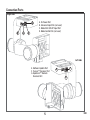
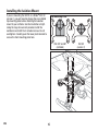
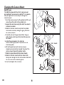
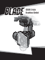
®
GB200 2-Axis
Brushless Gimbal
1
EN
NOTICE
All instructions, warranties and other collateral documents are subject to change at the sole discretion of
Horizon Hobby, LLC. For up-to-date product literature, visit horizonhobby.com and click on the support tab for
this product.
Meaning of Special Language
The following terms are used throughout the product literature to indicate various levels of potential harm
when operating this product:
NOTICE: Procedures, which if not properly followed, create a possibility of physical property damage AND a
little or no possibility of injury.
CAUTION: Procedures, which if not properly followed, create the probability of physical property damage AND
a possibility of serious injury.
WARNING: Procedures, which if not properly followed, create the probability of property damage, collateral
damage, and serious injury OR create a high probability of superficial injury.
WARNING: Read the ENTIRE instruction manual to become familiar with the features of the product
before operating. Failure to operate the product correctly can result in damage to the product, personal
property and cause serious injury.
This is a sophisticated hobby product. It must be operated with caution and common sense and requires some
basic mechanical ability. Failure to operate this Product in a safe and responsible manner could result in injury
or damage to the product or other property. This product is not intended for use by children without direct adult
supervision. Do not use with incompatible components or alter this product in any way outside of the instructions provided by Horizon Hobby, LLC. This manual contains instructions for safety, operation and maintenance.
It is essential to read and follow all the instructions and warnings in the manual, prior to assembly, setup or
use, in order to operate correctly and avoid damage or serious injury.
Age Recommendation: Not for children under 14 years. This is not a toy.
EN
2
Safety Precautions and Warnings
• Always keep a safe distance in all directions
around your model to avoid collisions or injury. This
model is controlled by a radio signal subject to interference from many sources outside your control.
Interference can cause momentary loss of control.
• Always operate your model in open spaces away
from full-size vehicles, traffic and people.
• Always carefully follow the directions and warnings
for this and any optional support equipment
(chargers, rechargeable battery packs, etc.).
• Always keep all chemicals, small parts and anything electrical out of the reach of children.
• Always avoid water exposure to all equipment
not specifically designed and protected for this
purpose. Moisture causes damage to electronics.
• Never place any portion of the model in your mouth
as it could cause serious injury or even death.
• Never operate your model with low transmitter
batteries.
• Always keep the aircraft in sight and under control.
• Always move the throttle fully down at rotor strike.
• Always use fully charged batteries.
• Always keep the transmitter powered on while the
aircraft is powered.
• Always remove batteries before disassembly
• Always keep moving parts clean.
• Always keep parts dry.
• Always let parts cool after use before touching.
• Always remove batteries after use.
• Never operate an aircraft with damaged wiring.
• Never touch moving parts.
3
EN
Table of Contents
Box Contents ........................................................... 4
Connection Ports...................................................... 5
Installing the Isolation Mount ................................... 6
Routing the Wiring ................................................... 7
Changing the Camera Mount.................................... 8
Installing the Gimbal ................................................ 9
Mounting the Camera ............................................ 10
Gimbal Modes........................................................ 11
Transmitter Programming ...................................... 11
Using the Gimbal ................................................... 12
LED Codes ............................................................. 12
Troubleshooting ..................................................... 13
Box Contents
A. GB200 2-Axis Camera Gimbal
w/CGO1 compatible mounting plate
B. Assembled isolation mount
C. (4) Mounting Screws
D. Knurled 3mm screw
E. 3-wire harness
F. 2-wire power harness
G. Alternate top mounting plate
H. GoPro® (3/3+) compatible camera mounting plate
I. (3) 2-wire harnesses (not used)
J. Small hex wrench
K. Large hex wrench
Copper foil RF shield (not shown)
B
A
G
E
C
J
D
EN
H
K
4
F
I
Connection Ports
Right side
A
B
C
D
A. 5V Power Port
B. Universal Input Port (not used )
C. Blade 350 QX2/AP Input Port
D. Mode Control Port (not used )
Left side
E. Software Update Port
F. Yuneec™ Receiver Port
G. Spektrum™ Remote
Receiver Port
5
F
E
G
EN
Installing the Isolation Mount
If you are mounting the GB200 on a Blade® 350 QX
(version 1), you will need to change the pre-installed
top mounting plate before attaching the isolation
mount to your airframe. See the illustration at right.
Using the large hex wrench provided, install the
isolation mount with the 4 included screws. Do not
overtighten. Carefully push the lower plate forward to
access the front mounting plate hole.
Top Mounting Plate
Front
350 QX2 and AP
(installed)
EN
6
350 QX
(version 1)
Routing the Wiring
• If you are installing the GB200 on a Blade 350 QX
(version 1), use the included 2-wire harness (red
and brown).
• If you are installing the GB200 on a Blade 350 QX2
or 350 QX2 AP, use the included 3-wire harness
(red, brown and orange).
1. Plug the servo connector into the flight control
board as shown.
2. Route the JST connector through the hole in the
landing gear mount on the bottom of the 350 QX.
2
1
2
7
EN
Changing the Camera Mount
GoPro® users
The GB200 comes with the CGO1 camera mount
pre-installed. If you are using a GoPro® 3/3+ camera
with your gimbal, it is necessary to change the
camera mount.
1. Turn the camera mount on the gimbal until the set
screw faces the notch in the gimbal arm.
2. Loosen the set screw using the small hex wrench
included, as shown.
3. Slide the camera mount away from the gimbal
motor while carefully sliding the gyro plate from
the camera mount.
4. Carefully remove the gyro board from the gyro
plate. Double-stick tape firmly holds the board on
the mount.
5. Install the gyro board in the alternate
camera mount gyro plate. The plates are not
interchangeable.
6. Wrap the gyro board wire harness loosely
clockwise one whole turn around the end of the
camera mount toward the gimbal motor.
7. Slide the gyro plate onto the camera mount.
8. Slide the camera mount onto the motor shaft,
taking care to align the flat on the motor shaft with
the set screw on the mounting plate.
9. Insert and tighten the set screw.
EN
2
3
3
6
8
CGO1 mount
9
5
7
GoPro® 3 mount
8
Installing the Gimbal
Install the gimbal with the vertical arm to the rear by
lining up the tracks of the gimbal and the mount and
pushing towards the rear of the plate as shown at left.
To remove the gimbal, push in the restraining clip and
pull the gimbal forward from the slot.
Plug the wire routed from the control board to the
correct port in the gimbal. See Connection Ports for
the port layout.
350 QX2 or 350 QX2 AP:
Insert the 3-wire harness into the Blade 350 QX2/AP
Input Port as shown at the left.
350 QX:
Insert the 2-wire harness into the Power Port. The
gimbal will stabilize roll and pitch normally, but will
have no transmitter control of the pitch axis.
If you wish to have transmitter control of the pitch
axis, a seperate remote receiver is required
(see below ).
Using a Remote Receiver for Pitch Axis Control
On the original 350 QX quadcopter, the gimbal will
automatically level without installation of an optional
remote receiver. If transmitter control of the pitch
axis is desired, connect a Spektrum Remote Receiver
(SPM9645, sold separately ) to gimbal port G. Secure
the remote receiver to the upper gimbal body using
double-stick tape. Bind the remote receiver while
binding the quadcopter receiver to your transmitter.
If the gimbal does not respond to the transmitter,
re-bind.
9
EN
Mounting the Camera
IMPORTANT: Consult local laws and ordinances before installing and operating any type of photograph-capable
or video recording device in a hobby model aircraft.
CGO1
1. Slide the camera fully into the gimbal as shown.
2. Install the 3mm screw through the mount and into
the camera body as shown.
3. Insert the Wi-Fi antenna through the mount and
into the camera body until it clicks. Rotate the
antenna 90° in either direction to lock.
1
3
2
GoPro® 3/3+
1. Install the included copper foil shield around the
camera body using the included instructions.
2. Slide the camera and shield fully into the gimbal
as shown.
3. Slide the rubber strap around the camera body and
lens as shown.
2
1
EN
10
3
Gimbal Modes
Angle Mode (Green LED)
• The gimbal pitch angle corresponds directly to the
position of the transmitter control input.
• The gimbal will automatically stabilize in the
stopped position.
Velocity Mode (Blue LED)
• The gimbal pitch angle moves away from neutral in
the direction of the transmitter control input.
• The farther away from center the transmitter
control input is, the faster the gimbal moves in the
corresponding direction.
• The pitch angle movement is stopped by centering
the transmitter control.
• The gimbal will automatically stabilize in the
stopped position.
Transmitter Programming
Transmitter control of the pitch angle of the GB200 is
possible with most 7-channel and above Spektrum
transmitters.
For the greatest control of the gimbal functions, an
8-channel or higher computer radio is recommended.
If you are using a DX7S system:
• Angle Mode will be active if you use the signal
output from the 350QX2/AP control board.
• Velocity Mode will be active if you use only the
power output from the 350 QX/2/AP in conjunction
with a remote receiver.
To program your transmitter:
• Set channel 7 to a dial, slider or lever for gimbal
pitch control.
• Change channel 7 servo reverse for the gimbal
travel direction you prefer.
• Set channel 8 to a 2-position switch to choose
between gimbal modes.
• Change channel 8 servo reverse for the switch
direction you prefer.
If you are using a DX7 system:
• The DX7 uses a 2-position switch on channel 7.
When using this transmitter, the gimbal will default
to Angle Mode and will travel to either full up or full
down, depending on the position of the channel
7 switch. You can adjust the endpoints in your
transmitter to achieve the desired camera angles.
11
EN
Using the Gimbal
1. Place the quadcopter on a flat and stable surface.
Ensure there are no obstructions in the path of the
GB200.
2. Switch on your transmitter.
3. Switch on your quadcopter. The GB200 will power
on with the quadcopter.
After the gimbal initializes, the LED will glow purple
for approximately 3 seconds. In those 3 seconds, the
camera mount may be rotated up or down by hand
to your desired neutral pitch position. When the LED
changes to green or blue, the neutral position is set
and the GB200 is ready for use.
The gimbal will now compensate for any roll and pitch
movements encountered by your quadcopter.
If desired, you may change the pitch angle of
the gimbal at any time using your programmed
transmitter controls.
NOTICE: You must have a camera mounted to the
GB200 for the gimbal to initialize properly.
LED Codes
Green
Angle Mode
No control(Power Only)
350 QX2/AP Port Connected
Remote Receiver Connected
Velocity Mode
No control(Power Only)
350 QX2/AP Port Connected
Remote Receiver Connected
Initialization Complete
Neutral Position Change Available
No Gyro Data
EN
12
Blue
Red
Purple
Troubleshooting
Problem
Possible Cause
Solution
The gimbal vibrates after
switching ON
Loose camera
Secure the camera in the mount
Gimbal does not respond to
control input
Gimbal did not initialize
Keep the quadcopter and gimbal level
and immobile for 5 seconds after
switching ON
Gimbal is not ON
Incorrect gimbal connections
Correctly connect gimbal
Gimbal does not respond to
transmitter
Optional remote receiver is not
bound
Re-bind receivers
Gimbal does not respond
to control inputs. RED and
BLUE LEDs are solid
Incorrect gimbal connections
Correctly connect gimbal
Gimbal is not ON and RED
LED flashes slowly
Gimbal gyro board damage
Repair or replace wiring or gyro board
Gimbal LED Flashing RED in
Angle or Velocity Mode
Sensor Error
Correctly connect gimbal, repair or
replace gimbal wiring or boards
13
EN
Exploded View
2
3
5
4
1
6
2
Replacement Parts
#
1
2
3
4
Part #
BLH7904
BLH7905
BLH7906
BLH7907
Description
Gimbal Arms: GB200
Gimbal Motors: GB200
Gimbal Mount: GB200
Gimbal Control Board: GB200
# Part #
Description
5 BLH7908 Camera mount CGO1: GB200
6 BLH7909 Camera mount Go Pro Hero 3: GB200
BLH7910 GB200 Brushless Gimbal
Optional Parts
Part #
Description
SPM9645 DSMX Remote Receiver
EN
14
15
EN
©2014 Horizon Hobby, LLC.
Blade and the Horizon Hobby logo are registered trademarks of Horizon Hobby, LLC.
The Spektrum trademark is used with permission of Bachmann Industries, Inc. GOPRO® is a registered trademark of Woodman Labs,
Inc. in the United States and other countries. Yuneec and CGO1 are trademarks of Yuneec International Co., Ltd.
All other trademarks, service marks or logos are property of their respective owners.
Patents pending.
Created 07/14 46284 BLH7910