1
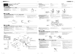
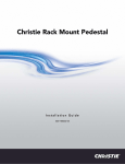
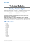
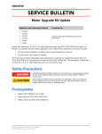
Christie Heat Extractor Kit
User Manual
020-100834-02
Christie Heat Extractor Kit
USER MANUAL
020-100834-02
NOTICES
COPYRIGHT AND TRADEMARKS
© 2012 Christie Digital Systems USA, Inc. All rights reserved.
All brand names and product names are trademarks, registered trademarks or trade names of their respective holders.
REGULATORY
The product has been tested and found to comply with the limits for a Class A digital device, pursuant to Part 15 of the FCC Rules.
These limits are designed to provide reasonable protection against harmful interference when the product is operated in a
commercial environment. The product generates, uses, and can radiate radio frequency energy and, if not installed and used in
accordance with the instruction manual, may cause harmful interference to radio communications. Operation of the product in a
residential area is likely to cause harmful interference in which case the user will be required to correct the interference at the
user’s own expense.
This Class A digital apparatus complies with Canadian ICES-003.
Cet appareil numérique de la classe A est conforme à la norme NMB-003 du Canada.
이 기기는 업무용 (A 급 ) 으로 전자파적합등록을 한 기기이오니 판매자 또는 사용자는 이점을 주의하시기 바라며 , 가정 외의 지역에서
사용하는 것을 목적으로 합니다 .
GENERAL
Every effort has been made to ensure accuracy, however in some cases changes in the products or availability could occur which
may not be reflected in this document. Christie reserves the right to make changes to specifications at any time without notice.
Performance specifications are typical, but may vary depending on conditions beyond Christie's control such as maintenance of
the product in proper working conditions. Performance specifications are based on information available at the time of printing.
Christie makes no warranty of any kind with regard to this material, including, but not limited to, implied warranties of fitness for
a particular purpose. Christie will not be liable for errors contained herein or for incidental or consequential damages in
connection with the performance or use of this material.
The product is designed and manufactured with high-quality materials and components that can be recycled and reused. This
symbol
means that electrical and electronic equipment, at their end-of-life, should be disposed of separately from regular
waste. Please dispose of the product appropriately and according to local regulations. In the European Union, there are separate
collection systems for used electrical and electronic products. Please help us to conserve the environment we live in!
Canadian manufacturing facility is ISO 9001 and 14001 certified.
GENERAL WARRANTY STATEMENTS
For complete information about Christie’s limited warranty, please contact your Christie dealer. In addition to the other limitations
that may be specified in Christie’s limited warranty, the warranty does not cover:
a. Damage occurring during shipment, in either direction.
b. Projector lamps (See Christie’s separate lamp program policy).
c. Damage caused by use of a projector lamp beyond the recommended lamp life, or use of a lamp supplied by a supplier other
than Christie.
d. Problems caused by combination of the product with non-Christie equipment, such as distribution systems, cameras, video
tape recorders, etc., or use of the product with any non-Christie interface device.
e. Damage caused by misuse, improper power source, accident, fire, flood, lightening, earthquake or other natural disaster.
f. Damage caused by improper installation/alignment, or by product modification, if by other than a Christie authorized repair
service provider.
g. For LCD projectors, the warranty period specified applies only where the LCD projector is in “normal use.” “Normal use”
means the LCD projector is not used more than 8 hours a day, 5 days a week. For any LCD projector where “normal use” is
exceeded, warranty coverage under this warranty terminates after 6000 hours of operation.
h. Failure due to normal wear and tear.
PREVENTATIVE MAINTENANCE
Preventative maintenance is an important part of the continued and proper operation of your product. Please see the
Maintenance section for specific maintenance items as they relate to your product. Failure to perform maintenance as required,
and in accordance with the maintenance schedule specified by Christie, will void the warranty.
Table of Contents
1: The Christie Heat Extractor Kit
1.1 Compatibility ...............................................................................................................................1-1
1.2 What’s In the Box? ......................................................................................................................1-1
1.3 Safety Precautions .......................................................................................................................1-2
1.4 Install the Heat Extractor Kit.......................................................................................................1-2
1.5 Maintenance.................................................................................................................................1-4
1.6 Specifications...............................................................................................................................1-4
2: 科视散热套件
2.1 兼容性 ........................................................................................................................... 2-1
2.2 包装箱内物品清单 ......................................................................................................... 2-1
2.3 安全警示信息 ................................................................................................................ 2-2
2.4 安装散热套件 ................................................................................................................ 2-2
2.5 维护 .............................................................................................................................. 2-4
2.6 规格 .............................................................................................................................. 2-4
3: Kit d’extracteur de chaleur Christie
3.1 Compatibilité ...............................................................................................................................3-1
3.2 Contenu du coffret .......................................................................................................................3-1
3.3 Consignes de sécurité ..................................................................................................................3-2
3.4 Installation du kit d’extracteur de chaleur ...................................................................................3-2
3.5 Entretien.......................................................................................................................................3-4
3.6 Spécifications...............................................................................................................................3-4
4: Christie Wärmesauglüfter-Set
4.1 Kompatibilität ..............................................................................................................................4-1
4.2 Lieferumfang ...............................................................................................................................4-1
4.3 Sicherheitsvorkehrungen .............................................................................................................4-2
4.4 Installation des Christie Wärmesauglüfter-Sets ..........................................................................4-2
4.5 Wartung .......................................................................................................................................4-4
4.6 Technische Daten ........................................................................................................................4-4
5: Kit per estrattore di calore Christie
5.1 Compatibilità ..............................................................................................................................5-1
5.2 Contenuto della confezione ........................................................................................................5-1
5.3 Precauzioni di sicurezza .............................................................................................................5-2
5.4 Installazione del kit per estrattore di calore................................................................................5-2
5.5 Manutenzione .............................................................................................................................5-4
5.6 Specifiche tecniche .....................................................................................................................5-4
6: Christie 排気ファンキット
6.1 互換性 ........................................................................................................................... 6-1
6.2 梱包内容一覧 ................................................................................................................ 6-1
6.3 安全注意事項 ................................................................................................................ 6-2
The Christie Heat Extractor Kit User Manual
020-100834-02 Rev. 1 (03-2012)
i
Table of Contents
6.4 排気ファンキットの取り付け........................................................................................6-2
6.5 保守 ...............................................................................................................................6-4
6.6 仕様 ...............................................................................................................................6-4
7: Christie 열 추출기 세트
7.1 호환성............................................................................................................................7-1
7.2 기본 구성 .......................................................................................................................7-1
7.3 안전 유의사항................................................................................................................7-2
7.4 열 추출기 세트 설치.......................................................................................................7-2
7.5 유지 보수 .......................................................................................................................7-4
7.6 기술 사양 .......................................................................................................................7-4
8: Комплект вытяжной вентиляции Christie
8.1 Совместимость ...........................................................................................................................8-1
8.2 Комплект поставки ....................................................................................................................8-1
8.3 Требования техники безопасности...........................................................................................8-2
8.4 Установка комплекта вытяжной вентиляции..........................................................................8-2
8.5 Техническое обслуживание ......................................................................................................8-4
8.6 Характеристики..........................................................................................................................8-5
9: Kit del extractor de calor de Christie
9.1 Compatibilidad.............................................................................................................................9-1
9.2 Contenido de la caja.....................................................................................................................9-1
9.3 Medidas de seguridad ..................................................................................................................9-2
9.4 Instalación del kit del extractor de calor ......................................................................................9-2
9.5 Mantenimiento .............................................................................................................................9-4
9.6 Especificaciones...........................................................................................................................9-4
ii
The Christie Heat Extractor Kit User Manual
020-100834-02 Rev. 1 (03-2012)
1 The Christie Heat Extractor Kit
This document provides information and instructions for installing the Christie heat extractor kit
(P/N: 38-814008-61). Only accredited Christie technicians who are knowledgeable about the hazards
associated with high-voltage, ultraviolet exposure, and the high temperatures generated by the projector lamp
are authorized to assemble, install, and service the projector.
The Christie heat extractor moves air at a minimum rate of 600 cubic feet per minute (CFM); this is the
minimum airflow recommended for all of the listed projectors. The 1.82 meter (6 foot) duct can be used with
all of the listed projectors. However, the shorter 15 centimeter (6 inch) duct is only recommended for use with
Roadie 25K projectors when the projector is installed in a confined space. If the projector is installed in a
confined space and it is operating for extended periods, route the duct to the outside of the building to ensure
optimal airflow. If you are using a longer duct, you must install additional extractors to keep the projector cool.
When installing third party extractors, make sure they meet the minimum requirement of 600 CFM.
If you are stacking Roadie 25K projectors, a side-venting duct adapter (P/N: 108-100101-01) is required.
1.1
Compatibility
The Christie heat extractor is compatible with these projectors:
•
•
•
•
•
1.2
Roadie 25K
Roadie HD+30K/+35K (when the Christie exhaust kit (P/N: 113-107109-xx) is installed)
CP2000/SB/XB/ZX
CP2220/30
CP4220/30
What’s In the Box?
Every Christie heat extractor kit (P/N: 38-814008-61) includes these parts:
•
•
•
•
•
•
1.82 meters (6 feet) OR 15.24 centimeters (6 inches) corrugated exhaust hose
Extractor
3 wire safety cables
6 snap hooks (carabiners)
4 extractor couplers (attached to the exhaust hose)
4 ring couplers (attached to the exhaust hose)
If you are missing parts from your Christie heat extractor kit, contact Christie support.
The Christie Heat Extractor Kit User Manual
020-100834-02 Rev. 1 (03-2012)
1-1
Section 1: The Christie Heat Extractor Kit
1.3
Safety Precautions
When installing the Christie heat extractor kit, observe these important safety rules to avoid personal injury or
damage to the projector:
DANGER
ELECTRICAL SHOCK HAZARD! Always power down and disconnect/disengage all
power sources to the projector before servicing or cleaning.
WARNING Never disable a vane switch. Operating a projector without airflow monitoring can
damage the projector.
1.4
CAUTION
The extractor must be connected to 20 A maximum upstream breaker.
CAUTION
No serviceable parts. Extractor blades cannot be serviced.
Install the Heat Extractor Kit
Install additional extractors when ducting exceeds 1.82 meters (6 feet). The projector will shut down when
there is insufficient airflow. Do not mount the extractor directly on the projector because extractor vibration
can transfer to the image.
NOTE: Make sure you have an AC power receptacle available for the extractor. A 20 A maximum upstream
breaker is required when the power cord is connected to an AC receptacle.
1. If the projector is on, turn it off and allow it to cool a minimum of 15 minutes.
2. Disconnect AC power from the projector.
3. Attach the duct to the projector:
a. Align the duct with the top exhaust port on the projector.
b. Twist the duct to secure the flaps over the projector pins.
c. Verify:
• The duct is unobstructed and the exhaust hose is not twisted.
• All projector air vents are unobstructed.
• The vane switch moves freely.
1-2
The Christie Heat Extractor Kit User Manual
020-100834-02 Rev. 1 (03-2012)
Section 1: Introduction
4. Install the extractor:
a. Connect the duct to the extractor.
b. Twist to secure the flaps over the pins on the extractor and make sure the extractor grill faces down.
5. Install the safety cables:
a. For elevated installations or when using the 1.82 meter (6 foot) duct, attach the three safety cables; one
from the extractor to the FredFrame or structure holding the projector, one from the extractor to the
duct, and one from the extractor to the supporting structure.
b. For floor mount installations, attach one end of the safety cable to the extractor and the other end to the
igniter door latch.
The Christie Heat Extractor Kit User Manual
020-100834-02 Rev. 1 (03-2012)
1-3
Section 1: The Christie Heat Extractor Kit
6. Connect the extractor power cord to the projector or an AC receptacle. A 20 A maximum upstream breaker
is required when the power cord is connected to an AC receptacle.
7. Connect the projector to AC power.
8. Turn the projector on.
1.5
Maintenance
Vents and louvers in the projector covers provide ventilation, both for intake and exhaust. Never block or cover
these openings. Do not install the projector near a radiator, heat register, or within an enclosure. To ensure
adequate airflow around the projector, keep a minimum clearance of 50 cm (19.69 in) on the left and right sides
and the rear of the projector.
1.6
Specifications
Weight
Power Requirements
12 lb. (5.5 kg) extractor
230 V~ (nominal)
10 lb. (4.5 kg) long duct
50/60 Hz Line Frequency (nominal)
3 lb. (1.5 kg) short duct
160 W Power Consumption
(maximum)
1 A current rating of input
20 A maximum upstream breaker
1-4
Airflow
Output
600 CFM
(nominal)
Audible Noise/Sound Pressure
60 dBA*
*Measured as per ISO 3744
standard, which measures the
average free field values at a radius
of 1 m from the extractor, fully
ducted and when located above a
reflecting plane. In application,
sound level will be affected by the
specifics of the installation.
The Christie Heat Extractor Kit User Manual
020-100834-02 Rev. 1 (03-2012)
2 科视散热套件
本文档为您提供安装科视散热套件 (P/N:38-814008-61)。只有经科视认证的技师才可以组装、安装和
维修投影机,因为他们了解高电压、紫外辐射和投影机灯泡所产生的高温可能带来的危险。
科视散热器的最小排气速率为每分钟 600 立方英尺 (CFM);该速率是所有在列投影机的建议最小
空气流速。1.82 米 (6 英尺)管道可用于所有在列投影机。但是,在封闭空间内安装 Roadie 25K 投
影机时,建议使用较短的 15 厘米 (6 英寸)管道。如果投影机安装在封闭空间内,而且要长时间使
用,请将管道接到建筑物外以确保气流通畅。如果您使用较长的管道,您必须另外安装散热器以冷却
投影机。在安装第三方散热器时,请确保散热器符合 600 CFM 的最低要求。
如果您要叠放 Roadie 25K 投影机,则需要安装侧通风管道转接器 (P/N:108-100101-01)。
2.1
兼容性
科视散热器与以下投影机兼容:
• Roadie 25K
• Roadie HD+30K/+35K (已安装科视散热套件 (P/N: 113-107109-xx)时)
• CP2000/SB/XB/ZX
• CP2220/30
• CP4220/30
2.2
包装箱内物品清单
每个科视散热套件 (P/N: 38-814008-61)包含以下部件:
•
•
•
•
•
•
1.82 米 (6 英尺)或 15.24 厘米 (6 英寸)排气波纹软管
散热器
3 条安全绳
6 个强力挂钩 (钩环)
4 个散热器耦合器 (连接到排气软管上)
4 个环形耦合器 (连接到排气软管上)
如您的科视散热套件中缺少任何部件,请联系科视支持中心。
科视散热套件用户手册
020-100834-02 修订版 1 (03-2012)
2-1
第 2 部分: 科视散热套件
2.3
安全警示信息
在安装科视散热套件时,请遵循以下重要安全规则,以避免人身伤害或投影机损坏:
电击危险! 在维修或清洁前,请务必先关闭投影机,并切断 / 断开所有电源。
决不要停用风门开关。 在不检测气流的情况下运行投影机有可能导致投影机损坏。
必须将散热器连接至最大电流为 20 A 的上游断路器。
没有可维修的部件。 散热器叶片无法维修。
2.4
安装散热套件
管道超过 1.82 米 (6 英尺)时,请附加安装其他散热器。气流不足时,投影机将自动关机。请勿将散
热器直接安装在投影机上,因为散热器的震动可能会影响到影像。
注:请确保使用适用于散热器的交流电插座。如将电源线连接至交流电插座,则需要安装最大电流为
20 A 的上游断路器。
1. 如投影机已开启,请将其关闭并至少冷却 15 分钟。
2. 断开投影机的交流电源。
3. 将管道连接到投影机上:
a. 将管道与投影机上方的排气端口对齐。
b. 旋转管道以将波纹管的管头固定在投影机的管脚上。
c. 检查:
• 管道内没有障碍物,排气软管没有扭结。
• 投影机所有通气孔内都没有障碍物。
• 风门开关能自由移动。
2-2
科视散热套件用户手册
020-100834-02 修订版 1 (03-2012)
第 1 部分: 简介
4. 安装散热器:
a. 将管道连接至散热器。
b. 旋转以将波纹管的管头固定在散热器的管脚上,并确保散热器栅格朝下。
5. 安装安全绳:
a. 如在高处安装或使用 1.82 米 (6 英尺)管道安装,请连接三条安全绳;一条从散热器连接至
FredFrame 或固定投影机的支架,一条从散热器连接到管道,一条从散热器连接到支撑架。
b. 如为地面固定安装,请将安全绳的一端连接至散热器,另一端连接至启动器门锁。
科视散热套件用户手册
020-100834-02 修订版 1 (03-2012)
2-3
第 2 部分: 科视散热套件
6. 将散热器电源线连接至投影机或交流电插座。如将电源线连接至交流电插座,则需要安装最大电
流为 20 A 的上游断路器。
7. 将投影机连接到交流电源。
8. 打开投影机。
2.5
维护
投影机盖上的通风口和排气孔为进气和排气提供了通道。决不要阻挡或覆盖这些开口。不要将投影机
安装在暖气、散热器附近或者安装在封闭外壳内。为确保投影机周围有足够的气流,请在投影机左
侧、右侧和后侧至少留有 50 厘米 (19.69 英寸)的空隙。
2.6
规格
重量
电源要求
12 磅 (5.5 千克)散热器
230 V~ (额定)
10 磅 (4.5 千克)长管道
50/60 Hz 线路频率 (额定)
3 磅 (1.5 千克)短管道
160 W 功率消耗 (最大)
1 A 额定输入电流
最大 20 A 的上游断路器
2-4
可听噪音 / 声压
气流输出
600 CFM
(额定)
60 dBA*
* 根据 ISO 3744 标准测量,即将
散热器连接上所有管道,并固定
在反射平面上方,然后测量散热
器周围半径为 1 米范围内的平均
自由场值。在实际应用中,音量
可能会受具体安装方式的影响。
科视散热套件用户手册
020-100834-02 修订版 1 (03-2012)
3 Kit d’extracteur de chaleur Christie
Le présent document fournit des informations et des instructions pour installer le kit d’extracteur de chaleur
Christie (Réf : 38-814008-61). Seuls les techniciens agréés par Christie, conscients de tous les risques associés
à la haute-tension, à l’exposition aux ultraviolets et aux températures élevées produites par l’ampoule du
projecteur sont autorisés à monter, installer et réaliser les interventions d’entretien sur le projecteur.
L’extracteur de chaleur Christie déplace l’air à un niveau minimum de 600 pieds cubes par minute (PCM) ; il
s’agit du débit d’air minimum recommandé pour l’ensemble des projecteurs listés. La conduite de 1,82 mètres
peut être utilisée avec l’ensemble des projecteurs listés. Cependant, la conduite raccourcie de 15 centimètres
est recommandée uniquement pour être utilisée avec les projecteurs Roadie 25K, lorsque le projecteur est
installé dans un espace restreint. Si le projecteur est installé dans un espace restreint et fonctionne pendant des
périodes prolongées, orientez la conduite vers l’extérieur du bâtiment afin de garantir un débit d’air optimal. Si
vous utilisez une conduite plus longue, vous devez installer des extracteurs supplémentaires pour maintenir le
projecteur froid. Lors de l’installation des extracteurs d’autres sociétés, assurez-vous de respecter le débit d’air
minimum requis de 600 PCM.
Si vous superposez des projecteurs Roadie 25K, un adaptateur pour la conduite de ventilation latérale
(Réf : 108-100101-01) est requis.
3.1
Compatibilité
L’extracteur de chaleur Christie est compatible avec les projecteurs suivants :
•
•
•
•
•
3.2
Roadie 25K
Roadie HD+30K/+35K (lorsque le kit d’échappement Christie (Réf : 113-107109-xx) est installé)
CP2000/SB/XB/ZX
CP2220/30
CP4220/30
Contenu du coffret
Chaque kit d’extracteur de chaleur Christie (Réf : 38-814008-61) comprend les éléments suivants :
•
•
•
•
•
•
un tuyau d’échappement en tôle ondulée de 1,82 mètres OU 15,24 centimètres
Extracteur
3 câbles de sécurité
6 mousquetons
4 coupleurs d’extracteur (fixés au tuyau d’échappement)
4 coupleurs de bague (fixés au tuyau d’échappement)
S’il manque des éléments dans votre kit d’extracteur de chaleur Christie, contactez l’assistance Christie.
Manuel d’utilisation du kit d’extracteur de chaleur Christie
020-100834-02 Rév. 1 (03-2012)
3-1
Section 3 : Kit d’extracteur de chaleur Christie
3.3
Consignes de sécurité
Lors de l’installation du kit d’extracteur de chaleur Christie, suivez ces règles de sécurité importantes pour
éviter les blessures corporelles ou l’endommagement du projecteur :
DANGER
RISQUE D’ÉLECTROCUTION ! Il faut systématiquement éteindre et déconnecter/
débrancher toutes les sources d’alimentation du projecteur avant de le nettoyer ou d’en effectuer la
maintenance.
AVERTISSEMENT Ne jamais désactiver un interrupteur à palette. Utiliser un projecteur sans surveiller le
débit d’air peut endommager le projecteur.
3.4
ATTENTION
L’extracteur doit être connecté à un sectionneur en amont de 20 A maximum.
ATTENTION
Aucune pièce réparable. Les lames de l’extracteur ne peuvent pas être entretenues.
Installation du kit d’extracteur de chaleur
Installez des extracteurs supplémentaires lorsque la conduite dépasse 1,82 mètres. Le projecteur s’arrêtera
lorsque le débit d’air n’est pas suffisant. Ne montez pas l’extracteur sur le projecteur, car les vibrations de
l’extracteur peuvent être transférées à l’image.
REMARQUE : assurez-vous d’avoir une prise c.a. disponible pour l’extracteur. Un sectionneur en amont de
20 A maximum est nécessaire lorsque le cordon d’alimentation est connecté à une prise c.a.
1. Si le projecteur est activé, mettez-le hors tension et laissez-le refroidir pendant au moins 15 minutes.
2. Débranchez l’alimentation secteur du projecteur.
3. Fixez la conduite au projecteur :
a. Alignez la conduite avec l’orifice d’échappement supérieur du projecteur.
b. Faites tourner la conduite pour fixer les crochets sur les broches du projecteur.
c. Vérifiez les points suivants :
• La conduite n’est pas obstruée et le tuyau d’échappement n’est pas tordu.
• Toutes les grilles d’entrée d’air du projecteur sont dégagées.
• L’interrupteur à palette bouge sans obstruction.
3-2
Manuel d’utilisation du kit d’extracteur de chaleur Christie
020-100834-02 Rév. 1 (03-2012)
Section 1 : Introduction
4. Installez l’extracteur :
a. Branchez la conduite à l’extracteur.
b. Faites tourner pour fixer les crochets sur les broches de l’extracteur et assurez-vous que les grilles de
l’extracteur sont orientées vers le bas.
5. Installez les câbles de sécurité :
a. Pour les installations élevées ou lorsque vous utilisez la conduite de 1,82 mètres, fixez les trois câbles
de sécurité, un à partir du FredFrame ou de la structure de soutien du projecteur, un à partir de
l’extracteur vers la conduite et un à partir de l’extracteur vers la structure de soutien.
b. Pour les montages au sol, fixez une extrémité du câble de sécurité à l’extracteur et l’autre extrémité à
la clenche de la porte de l’allumeur .
Manuel d’utilisation du kit d’extracteur de chaleur Christie
020-100834-02 Rév. 1 (03-2012)
3-3
Section 3 : Kit d’extracteur de chaleur Christie
6. Branchez le cordon d’alimentation de l’extracteur au projecteur ou à une prise secteur. Un sectionneur en
amont de 20 A maximum est nécessaire lorsque le cordon d’alimentation est connecté à une prise c.a.
7. Connectez le projecteur à l’alimentation c.a.
8. Allumez le projecteur.
3.5
Entretien
Les évents et les volets d’aération sur les couvercles du ventilateur assurent la ventilation, pour l’admission et
l’échappement. Ne jamais bloquer et couvrir ces ouvertures. Ne pas installer le projecteur à proximité d’un
radiateur, d’une grille de chauffage ou dans un boîtier. Pour garantir un débit d’air adéquat autour du
projecteur, prévoir un espace minimum de 50 cm sur les côtés gauche, droit et arrière de l’appareil.
3.6
Spécifications
Poids
Alimentation
Extracteur de 5,5 kg
230 V~ (nominal)
Conduite allongée
de 4,5 kg
Fréquence de ligne
(nominale) à 50/60 Hz
Conduite raccourcie
de 1,5 kg
Consommation d’énergie
(maximum) à 160 W
Courant nominal de l’alimentation
à1A
Sectionneur en amont
de 20 A maximum
3-4
Sortie du
débit
d’air
600 PCM
(nominal)
Bruit perceptible/Pression sonore
60 dBA*
*Mesuré en vertu de la norme ISO
3744, qui mesure les valeurs
moyennes en champ libre sur un
rayon de 1 m depuis l’extracteur,
indépendant et placé au-dessus d’un
plan réfléchissant. Dans la pratique,
les spécificités de l’installation
auront une incidence sur le niveau
sonore.
Manuel d’utilisation du kit d’extracteur de chaleur Christie
020-100834-02 Rév. 1 (03-2012)
4 Christie Wärmesauglüfter-Set
Dieses Dokument enthält Informationen und Anleitungen zur Installation des Christie Wärmesauglüfter-Sets
(Teilenr.: 38-814008-61). Nur von Christie qualifizierte Techniker, die über die potenziellen Gefahren in
Zusammenhang mit Hochspannung, Ultraviolettstrahlung und hohen Temperaturen, die von der Lampe
erzeugt werden, informiert sind, dürfen den Projektor zusammenbauen, installieren und Wartungsfunktionen
durchführen.
Der Christie Wärmesauglüfter bewegt Luft von mindestens 600 Kubikfuß pro Minute (CFM); hierbei handelt
es sich um den für alle aufgeführten Projektoren empfohlenen Mindest-Volumenstrom. Der 1,82 m (6 ft) lange
Kanal kann mit allen aufgeführten Projektoren verwendet werden. Der kürzere, 15 cm (6 Zoll) lange Kanal
wird jedoch nur für die Verwendung mit Roadie 25K-Projektoren empfohlen bei einer Projektoraufstellung in
kleinen Räumen. Wenn der Projektor in kleinen Räumen installiert wird und über längere Zeiträume in Betrieb
ist, sollte der Kanal zur Gebäudeaußenseite verlegt werden, um einen optimalen Luftstrom zu gewährleisten.
Bei Verwendung eines längeren Kanals müssen zusätzliche Sauglüfter installiert werden, um den Projektor vor
Überhitzung zu schützen. Bei der Installation von Sauglüftern anderer Hersteller muss sichergestellt werden,
dass diese den erforderlichen Volumenstrom von mindestens 600 CFM erfüllen.
Wenn Roadie 25K-Projektoren gestapelt werden, benötigen Sie einen Adapter für den Seitenlüftungskanal
(Teilenr.: 108-100101-01).
4.1
Kompatibilität
Der Wärmesauglüfter von Christie ist mit folgenden Projektoren kompatibel:
•
•
•
•
•
4.2
Roadie 25K
Roadie HD+30K/+35K (bei Installation des Christie-Abluftsets (Teilenr.: 113-107109-xx))
CP2000/SB/XB/ZX
CP2220/30
CP4220/30
Lieferumfang
Jedes Christie Wärmesauglüfter-Set (Teilenr.: 38-814008-61) enthält folgende Komponenten:
•
•
•
•
•
•
1 gewellter Abluftschlauch mit einer Länge von 1,82 m (6 ft) ODER 15,24 cm (6 Zoll)
Sauglüfter
3 Sicherheitsdrahtseile
6 Karabinerhaken
4 Sauglüfter-Verbindungsstücke (angebracht am Abluftschlauch)
4 Ringverbindungen (angebracht am Abluftschlauch)
Sollten in Ihrem Christie Wärmesauglüfter-Set Teile fehlen, wenden Sie sich bitte an den Kundendienst von
Christie.
Bedienungsanleitung zum Christie Wärmesauglüfter-Set
020-100834-02 Rev 1 (03-2012)
4-1
Kapitel 4: Christie Wärmesauglüfter-Set
4.3
Sicherheitsvorkehrungen
Bei der Installation des Christie Wärmesauglüfter-Sets sollten die folgenden wichtigen
Sicherheitsvorkehrungen getroffen werden, um Verletzungen oder Schäden am Projektor zu vermeiden:
GEFAHR
GEFAHR EINES ELEKTRISCHEN SCHLAGS! Den Projektor vor dem Durchführen von
Wartungs- oder Reinigungsarbeiten immer ausschalten und von der Stromversorgung trennen.
WARNHINWEIS Niemals einen Stellungsschalter deaktivieren. Der Projektorbetrieb ohne Überwachung
des Luftstroms kann den Projektor beschädigen.
VORSICHT
Der Sauglüfter muss an einen vorgeschalteten Leistungsschalter für maximal 20 A
angeschlossen werden.
VORSICHT
werden.
4.4
Teile, die nicht gewartet werden können. Die Lüfterflügel können nicht gewartet
Installation des Christie Wärmesauglüfter-Sets
Beträgt die Kanalführung mehr als 1,82 m (6 ft), müssen zusätzliche Sauglüfter installiert werden. Der
Projektor schaltet sich bei unzureichendem Luftstrom ab. Befestigen Sie den Sauglüfter nicht direkt am
Projektor, da die Vibration des Sauflüfters zu Bildstörungen führen kann.
HINWEIS: Für den Sauglüfter ist eine Wechselstromsteckdose erforderlich. Ein vorgeschalteter
Leistungsschalter für maximal 20 A ist erforderlich, wenn das Netzkabel an eine WechselstromGerätesteckdose geschlossen wird.
1. Ist der Projektor eingeschaltet, schalten Sie ihn aus und lassen Sie ihn 15 Minuten abkühlen.
2. Trennen Sie den Projektor vom Wechselstrom.
3. Befestigen Sie den Kanal am Projektor:
a. Verbinden Sie dazu den Lüftungskanal mit der Absaugöffnung nach oben.
b. Drehen Sie den Kanal, um die Klappen über den Projektorstiften zu sichern.
c. Überprüfen Sie, ob Folgendes gewährleistet ist:
• Der Kanal ist frei und der Abluftschlauch ist nicht verdreht.
• Die Lüftungsschlitze des Projektors sind frei.
• Der Stellungsschalter kann frei bewegt werden.
4-2
Bedienungsanleitung zum Christie Wärmesauglüfter-Set
020-100834-02 Rev 1 (03-2012)
Abschnitt 1: Einführung
4. Installation des Sauglüfters:
a. Schließen Sie den Kanal an den Sauglüfter.
b. Drehen Sie den Kanal, um die Klappen über den Sauglüfterstiften zu sichern. Das Gitter des
Sauglüfters muss dabei nach unten zeigen.
5. Installation der Sicherheitskabel:
a. Bei erhöhter Installation oder bei Verwendung eines 1,82 m (6 ft) langen Kanals müssen die drei
Sicherheitskabel angebracht werden: eines vom Sauglüfter zum FredFrame bzw. zur Konstruktion, die
den Projektor hält; eines vom Sauglüfter zum Kanal und eines vom Sauglüfter zur Stützkonstruktion.
b. Bei einer Bodenmontage müssen Sie ein Ende des Sicherheitskabels am Sauglüfter befestigen und das
andere Ende am Klappenriegel der Zündvorrichtung.
Bedienungsanleitung zum Christie Wärmesauglüfter-Set
020-100834-02 Rev 1 (03-2012)
4-3
Kapitel 4: Christie Wärmesauglüfter-Set
6. Schließen Sie das Netzkabel des Sauglüfters an den Projektor bzw. an eine Wechselstromsteckdose an. Ein
vorgeschalteter Leistungsschalter für maximal 20 A ist erforderlich, wenn das Netzkabel an eine
Wechselstrom-Gerätesteckdose geschlossen wird.
7. Schließen Sie den Projektor an die Wechselstromquelle an.
8. Schalten Sie den Projektor ein.
4.5
Wartung
Belüftungslöcher und Luftklappen in der Projektorabdeckung sorgen für Belüftung der Ein- und
Auslasslüftung. Diese Öffnungen niemals blockieren oder abdecken. Installieren Sie den Projektor nicht in der
Nähe von Heizkörpern, Heizungsgittern, Wärmeschiebern oder innerhalb eines Gehäuses. Um eine
ausreichende Luftströmung um den Projektor zu gewährleisten, halten Sie einen Mindestabstand von 50 cm
(19,69 Zoll) links und rechts vom Projektor sowie von der Rückseite des Geräts ein.
4.6
Technische Daten
Gewicht
Sauglüfter: 5,5 kg
(12 lb.)
langer Kanal: 4,5 kg
(10 lb.)
kurzer Kanal: 1,5 kg
(3 lb.)
4-4
Erforderliche Stromversorgung
230 V~ (Nennwert)
50/60 Hz Zeilenfrequenz
(Nennwert)
160 W Leistungsaufnahme (max.)
1 A Nenneingangsstrom
Vorgeschalteter Leistungsschalter
für max. 20 A
Volumenstrom
600 CFM
(Nennwert)
Hörbare Störgeräusche/
Schalldruckpegel
60 dBA*
*Messung gemäß ISO 3744
Standard, wobei die FreifeldDurchschnittswerte in einem
Radius von 1 m zum Sauglüfter
gemessen werden - komplett
angeschlossen und an einem
Standort über einer
reflektierenden Fläche. Während
der Anwendung wird der
Schallpegel von den
Gegebenheiten der Anlage
beeinflusst.
Bedienungsanleitung zum Christie Wärmesauglüfter-Set
020-100834-02 Rev 1 (03-2012)
5 Kit per estrattore di calore Christie
Questo documento fornisce informazioni e istruzioni in merito all'installazione del kit per estrattore di calore
Christie (N/P: 38-814008-61). Le attività di assemblaggio, installazione e assistenza relativa al proiettore
devono essere svolte esclusivamente da tecnici certificati Christie, ovvero personale a conoscenza dei rischi
associati all'alta tensione, all'esposizione ai raggi UV e alle temperature elevate generate dalla lampada del
proiettore.
L'estrattore di calore Christie opera a una portata minima di 17 m3/min; questo è il flusso d'aria minimo
consigliato per tutti i proiettori in elenco. Il condotto da 1,82 m può essere utilizzato con tutti i proiettori
elencati. Di contro, il condotto più corto da 15 cm è consigliato esclusivamente per l'uso con proiettori Roadie
25K installati in spazi ristretti. Se il proiettore è installato in uno spazio ristretto e messo in funzione per
periodi di tempo prolungati, posizionare il condotto orientandolo verso l'esterno dell'edificio al fine di
assicurare un flusso d'aria ottimale. Se si utilizza un condotto più lungo, è necessario installare estrattori
aggiuntivi per mantenere il raffreddamento del proiettore. In caso di installazione di estrattori di terze parti,
assicurarsi che sia soddisfatto il requisito minimo di 17 m3/min.
In caso di sovrapposizione di proiettori Roadie 25K, utilizzare un adattatore per il condotto di ventilazione
laterale (N/P: 108-100101-01).
5.1 Compatibilità
L'estrattore di calore Christie è compatibile con i seguenti proiettori:
•
•
•
•
•
Roadie 25K
Roadie HD+30K/+35K (con kit di scarico Christie (N/P: 113-107109-xx) installato)
CP2000/SB/XB/ZX
CP2220/30
CP4220/30
5.2 Contenuto della confezione
Ogni kit per estrattore di calore Christie (N/P: 38-814008-61) include questi componenti:
•
•
•
•
•
•
Tubo corrugato di scarico da 1,82 m O 15,24 cm
Estrattore
Cavi di sicurezza a 3 fili
6 moschettoni (ganci a carabina)
4 accoppiatori per estrattore (collegati al tubo di scarico)
4 accoppiatori ad anello (collegati al tubo di scarico)
In caso di componenti mancanti nel kit per estrattore di calore Christie, contattare il supporto di Christie.
Manuale dell'utente del kit per estrattore di calore Christie
020-100834-02 Rev. 1 (03-2012)
5-1
Sezione 5: Kit per estrattore di calore Christie
5.3 Precauzioni di sicurezza
Durante l'installazione del kit per estrattore di calore Christie, osservare queste importanti norme di sicurezza
per evitare lesioni personali o danni al proiettore:
PERICOLO PERICOLO DI SCOSSA ELETTRICA. Prima di effettuare interventi di pulizia o assistenza,
assicurarsi di spegnere il proiettore e di scollegare/rimuovere tutte le fonti di alimentazione collegate
allo stesso.
AVVERTENZA Non disattivare mai l'interruttore della ventola. La messa in funzione del proiettore
senza il controllo del flusso d'aria può provocare danni all'unità.
ATTENZIONE L'estrattore deve essere collegato a un interruttore a monte da massimo 20 A.
ATTENZIONE Non sono presenti parti utilizzabili per scopi di manutenzione o riparazione. Questa
limitazione è pertinente anche alle pale dell'estrattore.
5.4 Installazione del kit per estrattore di calore
Installare estrattori aggiuntivi se il condotto supera una lunghezza di 1,82 m. In caso di flusso d'aria
insufficiente, il proiettore si spegne. Evitare di montare l'estrattore direttamente sul proiettore, dal momento
che la vibrazione dell'estrattore potrebbe pregiudicare la qualità di trasmissione dell'immagine.
NOTA: assicurarsi di disporre di una presa di corrente CA da utilizzare con l'estrattore. Se il cavo di
alimentazione è collegato alla presa CA, è necessario disporre di un interruttore a monte da massimo 20 A.
1. Se acceso, il proiettore deve essere spento per almeno 15 minuti al fine di consentire il raffreddamento.
2. Scollegare il proiettore dall'alimentazione CA.
3. Collegare il condotto al proiettore:
a. Allineare il condotto all'apertura di scarico superiore del proiettore.
b. Ruotare il condotto per bloccare le linguette sui perni del proiettore.
c. Verificare che siano valide le seguenti condizioni:
• Il condotto non è ostruito e il tubo di scarico non è sottoposto a torsione.
• Tutte le prese d'aria del proiettore non sono ostruite.
• L'interruttore della ventola non è bloccato.
5-2
Manuale dell'utente del kit per estrattore di calore Christie
020-100834-02 Rev. 1 (03-2012)
Sezione 1: Introduzione
4. Installare l'estrattore:
a. Collegare il condotto all'estrattore.
b. Ruotare per bloccare le linguette sui perni dell'estrattore, quindi verificare che la griglia dell'estrattore
sia rivolta verso il basso.
5. Installare i cavi di sicurezza:
a. In caso di installazioni elevate o di utilizzo del condotto da 1,82 m, collegare i tre cavi di sicurezza
come segue: dall'estrattore al FredFrame o alla struttura di alloggiamento del proiettore; dall'estrattore
al condotto e dall'estrattore alla struttura di supporto.
b. Per installazioni con montaggio a pavimento, collegare un'estremità del cavo di sicurezza all'estrattore
e l'altra alla serratura del portello del dispositivo di accensione.
Manuale dell'utente del kit per estrattore di calore Christie
020-100834-02 Rev. 1 (03-2012)
5-3
Sezione 5: Kit per estrattore di calore Christie
6. Collegare il cavo di alimentazione dell'estrattore al proiettore o a una presa CA. Se il cavo di alimentazione
è collegato alla presa CA, è necessario disporre di un interruttore a monte da massimo 20 A.
7. Collegare il proiettore all'alimentazione CA.
8. Accendere il proiettore.
5.5 Manutenzione
Le aperture e le feritoie di ventilazione nel proiettore consentono la ventilazione e servono sia per l'aspirazione
che per lo scarico dell'aria. Non bloccare né coprire queste aperture. Non installare il proiettore vicino a un
radiatore, un'altra fonte di calore o all'interno di uno spazio chiuso. Per garantire un flusso d'aria adeguato
attorno al proiettore, lasciare uno spazio libero di almeno 50 cm sui lati sinistro, destro e posteriore del
proiettore stesso.
5.6 Specifiche tecniche
Peso
Requisiti di alimentazione
5,5 kg per estrattore
Ca. 230 V (nominale)
4,5 kg per condotto
lungo
Frequenza di linea nominale:
50/60 Hz
1,5 kg per condotto
corto
Consumo energetico massimo:
160 W
Corrente nominale di ingresso: 1 A
Interruttore a monte: max. 20 A
5-4
Uscita
flusso
d'aria
17 m3/min
(nominale)
Rumore udibile/Pressione sonora
60 dBA*
*Conforme allo standard ISO 3744, in
accordo al quale si misurano valori di
campo libero medi nel raggio di 1 m
intorno all'estrattore completamente
collegato e posizionato su un piano
riflettente. In fase di utilizzo, il livello
acustico è influenzato dalle specifiche di
installazione.
Manuale dell'utente del kit per estrattore di calore Christie
020-100834-02 Rev. 1 (03-2012)
6 Christie 排気ファンキット
本文書には Christie 排気ファンキットの取り付けに関する説明と手順が記載されています。(排気
ファンキット P/N:38-814008-61). プロジェクターを組み立て、取り付け、修理サービスする権限
は、高電圧、紫外線暴露、およびプロジェクターランプから発生する高温に関連する危険性に精通
し、資格の有る Christie 技術者のみに与えられています。
Christie 排気ファンは、最低流量 600 CFM で排気します。この流量は全プロジェクターの推奨最低
流量です。1.82 メートル(6 フィート)ダクトは、当社の全プロジェクターに使用できます。ただ
し、Roadie 25K プロジェクターを狭いスペースに取り付ける場合は、短形の 15 センチメートル
(6 インチ)ダクトのみが推奨されます。狭いスペースにプロジェクターを取り付け、長時間にわ
たって使用する場合、排気流量を最適化するために屋外までダクトを配管してください。長いダク
トを使用する場合、プロジェクターを低温に維持するために追加の排気ファンを取り付ける必要が
あります。第三者製の換気ファンを取り付ける場合は、600 CFM の最低流量要件を満たしているこ
とを確認してください。
Roadie 25K プロジェクターを積み上げて使用する場合、側面放出ダクトアダプター
(P/N:108-100101-01)が必要になります。
6.1
互換性
Christie 排気ファンは、以下のプロジェクターと互換性があります。
• Roadie 25K
• Roadie HD+30K/+35K(Christie 排気ファンキット(P/N:113-107109-xx)を取り付ける場合)。
• CP2000/SB/XB/ZX
• CP2220/30
• CP4220/30
6.2
梱包内容一覧
各 Christie 排気ファンキット(P/N:38-814008-61)には以下の部品が含まれています。
• 1.82 メートル(6 フィート)または 15.24 センチメートル(6 インチ)コルゲート排気ホース
• 換気ファン
• 安全ケーブル 3 本
• スナップフック 6 個(カラビナ)
• 排気ファンカプラー 4 個(排気ホースに装着)
• リングカプラー 4 個(排気ホースに装着)
Christie 排気ファンキットに上記梱包内容一覧に記載されている部品がない場合、Christie サポート
までご連絡ください。
Christie 排気ファンキット ユーザーマニュアル
020-100834-02 改訂版 1 (03-2012)
6-1
セクション 6: Christie 排気ファンキット
6.3
安全注意事項
Christie 排気ファンキットを取り付ける際、以下の重要な安全規則に従い怪我やプロジェクターの
損傷を防いでください。
感電の危険性があります。修理または清掃を行う前に、必ずプロジェクターの電源を切り、す
べての電源装置をコンセントから外してください。
ベーンスイッチは絶対に無効化しないでください。気流量の監視を行なわずにプロジェク
ターを操作しないでください。プロジェクターの故障の原因になります。
排気ファンは最大 20 A 上流ブレーカーに接続する必要があります。
修理サービスできる部品はありません。排気ファンのブレードは修理サービスできません。
6.4
排気ファンキットの取り付け
ダクト長さが 1.82 メートル(6 フィート)を超える場合は、追加の排気ファンを取り付けてくださ
い。気流量が十分でないと、プロジェクターは停止します。換気ファンをプロジェクターに直接取
り付けないでください。直接取り付けると画像がぶれることがあります。
注:プロジェクターに AC レセプタクルが装備されていることを確認してください。電源コードを
AC レセプタクルに接続するには、最大 20A の上流ブレーカーが必要になります。
1. プロジェクターがオンになっている場合、オフにして、最低 15 分間冷却させます。
2. プロジェクターを AC 電源から外します。
3. ダクトをプロジェクターに装着します。
a. プロジェクターの上部排気ポートにダクトを合わせます。
b. ダクトをひねり、プロジェクターのピンにフラップを固定します。
c. 確認事項:
• ダクトに詰まりがなく、排気ホースが捻じれていないこと。
• すべてのプロジェクターの通気口が塞がっていないこと。
• 翼形スイッチが自由に動くこと。
6-2
Christie 排気ファンキット ユーザーマニュアル
020-100834-02 改訂版 1 (03-2012)
セクション 1: はじめに
4. 排気ファンの取り付け:
a. ダクトを排気ファンに接続します。
b. ひねって、排気ファンのピンにフラップを固定します。排気ファンのグリルは正面が下に
なっていることを確認してください。
5. 安全ケーブルの取り付け:
a. 高架設置や、1.82 メートル(6 フィート)ダクトを使用する場合、3 本の安全ケーブルを接
続します。1 本は排気ファンから FredFrame(プロジェクターの保持構造物)へ、1 本は排
気ファンからダクトへ、そして最後の 1 本は排気ファンから指示構造物へと接続します。
Christie 排気ファンキット ユーザーマニュアル
020-100834-02 改訂版 1 (03-2012)
6-3
セクション 6: Christie 排気ファンキット
b. フロア マウント設置には、安全ケーブルの一端を排気ファンに接続し、もう一方の端をイ
グナイター ドア ラッチスに接続します。
6. プロジェクターの電源コードをプロジェクターまたは AC レセプタクルに接続します。電源
コードを AC レセプタクルに接続するには、最大 20 A の上流ブレーカーが必要になります。
7. プロジェクターを AC 電源に接続します。
8. プロジェクターをオンにします。
6.5
保守
各プロジェクター カバー内の通気口およびルーバーは、吸気と排気の両方に対する換気を行いま
す。これらの開口部は、絶対にふさいだり覆ったりしないでください。本プロジェクターは、放熱
器、ヒート レジスターの近く、または筐体内部に設置しないでください。プロジェクター周辺に適
切な空気流を維持するために、プロジェクターの左右、後部との間には 50 cm(19.69 インチ)以上
のすき間を保つようにしてください。
6.6
仕様
重量
電源要件
5.5 kg(12 lb.)換気ファン
230 V ~(公称値)
4.5 kg(10 lb.)長形ダクト
50/60 Hz 線周波数(公称値)
1.5 kg(3 lb.)短形ダクト
160 W 消費電力(最大値)
1 A 入力定格電流
最大 20 A 上流ブレーカー
6-4
気流出力
600 CFM
(公称値)
可聴ノイズ / 音圧
60 dBA*
*ISO 3744 規格に従った測定値。
これは、完全にダクト処理し、
反射面上に配置した排気ファン
から半径 1 メートルの自由音場
の平均測定値です。実際のアプ
リケーションでは、音響レベル
は取り付けの仕様によって異な
ります。
Christie 排気ファンキット ユーザーマニュアル
020-100834-02 改訂版 1 (03-2012)
7 Christie 열 추출기 세트
본 설명서에서는 Christie 열 추출기 세트를 설치하는 데 필요한 정보 및 지침을 제공합니다
(P/N: 38-814008-61). 고전압, 자외선 노출, 프로젝터 램프에서 발생되는 고온과 관련된 위험에
대해 잘 알고 있는 Christie 공인 기술자만 프로젝터를 조립, 설치하고 서비스를 제공할 수 있습니다.
Christie 열 추출기는 최소 600CFM(분당 입방피트)의 속도로 공기를 이동시키는데, 이 속도는 나열된
모든 프로젝터에 권장되는 최소 공기 흐름입니다. 나열된 모든 프로젝터에서 사용할 수 있는 배관의
길이는 1.82m(6피트)입니다. 그러나, 더 짧은 15cm(6인치) 배관은 프로젝터를 한정된 공간에 설치할 경
우 Roadie 25K 프로젝터에서만 사용하는 것이 좋습니다. 프로젝터를 한정된 공간에 설치하여 장기간
사용할 경우, 배관을 건물 외부로 연결하여 공기가 잘 순환되도록 합니다. 더 긴 배관을 사용할 경우 프
로젝터가 적정 온도를 유지하도록 추출기를 추가로 설치해야 합니다. 타사 추출기를 설치할 경우 추출
기가 최소 요구 사항인 600CFM을 충족하는지 확인하십시오.
Roadie 25K 프로젝터를 쌓아 설치할 경우 측면 배출 배관 어댑터(P/N: 108-100101-01)가 필요합니다.
7.1
호환성
Christie 열 추출기는 다음 프로젝터와 호환됩니다.
• Roadie 25K
• Roadie HD+30K/+35K(Christie 배기관 세트(P/N: 113-107109-xx)가 설치된 경우)
• CP2000/SB/XB/ZX
• CP2220/30
• CP4220/30
7.2
기본 구성
모든 Christie 열 추출기 세트(P/N: 38-814008-61)에 기본 제공되는 부품 목록:
• 1.82m(6피트) 또는 15.24cm(6인치)의 주름진 배기관 호스
• 추출기
• 3선 안전 케이블
• 스냅 훅(카라비너) 6개
• 추출기 연결 장치 4개(배기관 호스에 부착)
• 링 연결 장치 4개(배기관 호스에 부착)
Christie 열 추출기 세트에서 부품이 빠졌을 경우 Christie 지원부에 문의하십시오.
Christie 열 추출기 세트 사용자 설명서
020-100834-02 개정 1 (03-2012)
7-1
7절: Christie 열 추출기 세트
7.3
안전 유의사항
Christie 열 추출기 세트를 설치할 때는 부상 또는 프로젝터 손상을 방지하기 위해 다음의 중요 안전 규
칙을 준수하시기 바랍니다.
감전 위험! 프로젝터를 수리하거나 청소하기 전에는 항상 전원을 끄고 모든 전원을 분리하십
시오.
날개 스위치를 끄지 마십시오. 공기 흐름을 살펴보지 않고 프로젝터를 작동하면 장비가 손상
될 수 있습니다.
추출기는 최대 20A의 상위 차단기에 연결되어야 합니다.
수리 가능한 부품이 없습니다. 추출기 날은 수리할 수 없습니다.
7.4
열 추출기 세트 설치
배관이 1.82m(6피트)를 초과하면 추출기를 추가로 설치합니다. 공기 순환이 좋지 않으면 프로젝터가 종료
됩니다. 추출기 진동이 이미지에 영향을 미칠 수 있으므로 추출기를 프로젝터 위에 장착하지 마십시오.
참고: 추출기를 AC 전원 콘센트에 연결할 수 있는지 확인하십시오. 전원 코드를 AC 콘센트에 연결할
경우 최대 20A의 상위 차단기가 필요합니다.
1. 프로젝터가 켜져 있으면 장비를 끄고 식을 때까지 최소 15분 정도 기다리십시오.
2. 프로젝터에서 AC 전원을 분리합니다.
3. 프로젝터에 배관 연결:
a. 배관을 프로젝터 윗부분의 배기관 포트에 맞춥니다.
b. 배관을 돌려 플랩을 프로젝터 핀에 고정시킵니다.
c. 확인할 사항:
• 배관이 막히지 않았으며 배기관 호스가 비틀어져 있지 않음
• 모든 프로젝터의 공기 통풍구에 방해물이 없음
• 날개 스위치가 자유자재로 움직임
7-2
Christie 열 추출기 세트 사용자 설명서
020-100834-02 개정 1 (03-2012)
1절: 서론
4. 추출기 설치 순서:
a. 배관을 추출기에 연결합니다.
b. 배관을 돌려 플랩을 추출기 핀에 고정시키고 추출기 그릴이 아래를 향하고 있는지 확인합니다.
5. 안전 케이블 설치 순서:
a. 높은 곳에 설치하거나 1.82m(6피트) 배관을 사용할 때는 추출기 ~ FredFrame 또는 프로젝터 지
지대, 추출기 ~ 배관, 추출기 ~ 지지대 사이에 각각 하나씩 총 3개의 안전 케이블을 연결합니다.
b. 바닥에 설치하는 경우에는 안전 케이블의 한 끝을 추출기에 연결하고 다른 쪽 끝을 이그나이터
문 걸쇠에 연결합니다.
Christie 열 추출기 세트 사용자 설명서
020-100834-02 개정 1 (03-2012)
7-3
7절: Christie 열 추출기 세트
6. 추출기 전원 코드를 프로젝터 또는 AC 콘센트에 연결합니다. 전원 코드를 AC 콘센트에 연결할 경
우 최대 20A의 상위 차단기가 필요합니다.
7. 프로젝터를 AC 전원에 연결합니다.
8. 프로젝터 전원을 켭니다.
7.5
유지 보수
프로젝터 덮개의 통풍구와 미늘창은 공기 흡입과 배출 시 모두 사용되는 환기 장치입니다. 따라서 이
개방구를 차단하거나 가리지 마십시오. 프로젝터를 전기 히터, 난방 통풍장치 부근 또는 폐쇄된 공간
내에 설치하지 마십시오. 프로젝터 주변의 공기 흐름이 원활하도록 프로젝터를 좌, 우측면과 후면에서
최소 50cm(19.69인치) 떨어뜨려 놓으십시오.
7.6
기술 사양
중량
전원 요구사항
5.5kg(12lb.) 추출기
230V ~ (공칭)
4.5kg(10lb.)의 긴 배관
50/60Hz 선 주파수(공칭)
1.5kg(3lb.)의 짧은 배관
160W 전원 소모(최대)
1A의 정격 입력 전류
최대 20A의 상위 차단기
7-4
공기 흐름 출력
600CFM(공칭)
가청 노이즈 / 사운드 압력
60dBA*
*반사면 상에 위치하고 배관을 완
전히 연결한 추출기를 대상으로
추출기로부터 1m 반경 내의 평균
여유 필드 값을 측정(ISO 3744 표
준 부합)합니다. 응용 시, 사운드
레벨은 자세한 설치 내용에 영향
을 받습니다.
Christie 열 추출기 세트 사용자 설명서
020-100834-02 개정 1 (03-2012)
8 Комплект вытяжной вентиляции Christie
Данный документ содержит сведения и инструкции по установке комплекта вытяжной вентиляции
Christie (артикул: 38-814008-61). Только уполномоченные технические специалисты компании Christie,
которые осведомлены обо всех опасностях, связанных с высоким напряжением, воздействием
ультрафиолетового излучения и высоких температур, создаваемых лампой проектора, могут выполнять
сборку, установку и обслуживание проектора.
Вытяжной вентилятор Christie перемещает воздух со скоростью не менее 600 кубических футов в
минуту. Это минимальная скорость потока воздуха, рекомендуемая для всех перечисленных
проекторов. Со всеми перечисленными проекторами может использоваться воздуховод длиной 1,82 м.
Однако более короткий 15-сантиметровый воздуховод рекомендуется использовать только с
проекторами Roadie 25K в случае их установки в замкнутых пространствах. Если проектор установлен
в замкнутом пространстве и работает в течение длительных периодов времени, следует вывести
воздуховод наружу с целью обеспечения оптимального воздушного потока. Если используется более
длинный воздуховод, следует обязательно установить дополнительные вытяжные вентиляторы для
надлежащего охлаждения проектора. При установке вытяжных вентиляторов сторонних
производителей следует убедиться, что они соответствуют минимальному требованию к
производительности в 600 кубических футов в минуту.
При монтаже нескольких проекторов Roadie 25K друг над другом должен использоваться воздуховодадаптер боковой вентиляции (артикул: 108-100101-01).
8.1
Совместимость
Вытяжной вентилятор Christie совместим со следующими проекторами.
• Roadie 25K
• Roadie HD+30K/+35K (при условии установки вытяжного комплекта Christie (артикул: 113-107109xx)
• CP2000/SB/XB/ZX
• CP2220/30
• CP4220/30
8.2
Комплект поставки
Каждый комплект вытяжной вентиляции Christie (артикул: 38-814008-61) содержит следующие детали.
•
•
•
•
•
•
Гофрированный вытяжной рукав длиной 1,82 метра ИЛИ 15,24 сантиметра.
Вытяжной вентилятор.
3 проволочных страховочных троса.
6 крюков с карабином.
4 муфты вытяжного вентилятора (прикреплены к вытяжному рукаву).
4 кольцевых ответвителя (прикреплены к вытяжному рукаву).
Если в комплекте вытяжной вентиляции Christie отсутствуют какие-либо детали, обратитесь в службу
поддержки Christie.
Руководство пользователя комплекта вытяжной вентиляции Christie
020-100834-02 Ред. 1 (03-2012)
8-1
Раздел 8. Комплект вытяжной вентиляции Christie
8.3
Требования техники безопасности
При установке комплекта вытяжной вентиляции Christie следует соблюдать следующие важные
правила техники безопасности во избежание получения травм и повреждения проектора.
ОПАСНО ОПАСНОСТЬ ПОРАЖЕНИЯ ЭЛЕКТРИЧЕСКИМ ТОКОМ! Перед началом
технического обслуживания или очистки всегда выключайте и отсоединяйте все источники
питания проектора.
ВНИМАНИЕ Никогда не отключайте флюгерный выключатель. Эксплуатация проектора без
контроля воздушного потока может привести к повреждению проектора.
ОСТОРОЖНО Перед вытяжным вентилятором должен быть подключен прерыватель
номиналом не более 20 А.
ОСТОРОЖНО Обслуживаемые детали отсутствуют. Лопасти вытяжного вентилятора не
подлежат ремонту.
8.4
Установка комплекта вытяжной вентиляции
Если длина воздуховода превышает 1,82 метра, следует установить дополнительные вытяжные
вентиляторы. При недостаточном потоке воздуха проектор отключается. Не устанавливайте вытяжной
вентилятор непосредственно на проектор, поскольку вибрация вентилятора может передаться на
изображение.
ПРИМЕЧАНИЕ. Убедитесь, что для вытяжного вентилятора есть свободная электрическая розетка.
При подключении шнура питания к электрической розетке на входе требуется прерыватель номиналом
не более 20 А.
1. Если проектор включен, выключите его и дайте ему остыть на протяжении не менее 15 минут.
2. Отключите проектор от сети переменного тока.
3. Присоедините воздуховод к проектору.
a. Совместите воздуховод с верхним выпускным патрубком на проекторе.
b. Проверните воздуховод, чтобы фиксаторы вошли в зацепление со штырьками на проекторе.
8-2
Руководство пользователя комплекта вытяжной вентиляции Christie
020-100834-02 Ред. 1 (03-2012)
Раздел 1. Введение
c. Проверьте следующее.
• Воздуховод ничем не перекрыт, а вытяжной рукав не перекручен.
• Все вентиляционные отверстия проектора ничем не перекрыты.
• Флюгерный выключатель двигается свободно.
4. Установите вытяжной вентилятор.
a. Соедините воздуховод с вытяжным вентилятором.
b. Проверните крепление, чтобы фиксаторы вошли в зацепление со штырьками на вытяжном
вентиляторе, и убедитесь, что решетка вентилятора направлена вниз.
Руководство пользователя комплекта вытяжной вентиляции Christie
020-100834-02 Ред. 1 (03-2012)
8-3
Раздел 8. Комплект вытяжной вентиляции Christie
5. Установите страховочные тросы.
a. При установке на высоте или при использовании воздуховода длиной 1,82 метра следует
прикрепить три страховочных троса: первый от вытяжного вентилятора до рамы FredFrame или
конструкции, удерживающей проектор, второй от вытяжного вентилятора до воздуховода и
третий от вытяжного вентилятора до несущей конструкции.
b. При напольной установке прикрепите один конец страховочного троса к вытяжному
вентилятору, а второй конец к защелке на дверце устройства зажигания.
6. Подключите шнур питания вытяжного вентилятора к проектору или электрической розетке. При
подключении шнура питания к электрической розетке на входе требуется прерыватель номиналом
не более 20 А.
7. Подключите проектор к сети переменного тока.
8. Включите проектор.
8.5
Техническое обслуживание
Вентиляционные отверстия и решетки на корпусе проектора предназначены как для забора свежего
воздуха, так и для выпуска горячего. Никогда не блокируйте и не закрывайте эти отверстия. Не
размещайте проектор около радиаторов, нагревателей, а также внутри замкнутого пространства. Для
обеспечения достаточного воздушного потока вокруг проектора убедитесь, что слева, справа и позади
него есть свободное пространство шириной не менее 50 см.
8-4
Руководство пользователя комплекта вытяжной вентиляции Christie
020-100834-02 Ред. 1 (03-2012)
Раздел 1. Введение
8.6
Характеристики
Вес
Требования к питанию
Вытяжной вентилятор
5,5 кг
230 В переменного тока
(номинальное значение)
Длинный воздуховод
4,5 кг
Частота напряжения сети
питания 50/60 Гц (номинальное
значение)
Короткий воздуховод
1,5 кг
Потребляемая мощность 160 Вт
(максимум)
Номинальный ток питания 1 А
Прерыватель на входе номиналом
не более 20 А
Руководство пользователя комплекта вытяжной вентиляции Christie
020-100834-02 Ред. 1 (03-2012)
Скорость
воздушного
потока
600
кубических
футов в
минуту
(номинальн
ое значение)
Слышимый шум/звуковое
давление
60 дБА*
* Измерено в соответствии со
стандартом ISO 3744, согласно
которому измеряются средние
значения для свободного
звукового поля в радиусе 1 м
вокруг вытяжного вентилятора,
который оснащен всеми
воздуховодами и расположен над
отражающей поверхностью. В
реальных условиях уровень
звукового давления будет
зависеть от специфики
конкретной установки.
8-5
9 Kit del extractor de calor de Christie
En este documento se proporcionan instrucciones e información sobre la instalación del kit del extractor de
calor de Christie (n.º de ref.: 38-814008-61). Solo los técnicos autorizados de Christie con conocimiento de los
peligros asociados a la alta tensión, la exposición a los rayos UVA y las altas temperaturas generadas por la
lámpara del proyector están autorizados para montar, instalar y reparar el proyector.
El extractor de calor de Christie mueve aire a un índice mínimo de 17 m3/min. (600 pies cúbicos por minuto,
CFM); este es el flujo de aire mínimo recomendado para todos los proyectores compatibles. El conducto de
1,82 metros (6 pies) se puede utilizar con todos los proyectores compatibles indicados. Sin embargo, el
conducto de 15 centímetros (6 pulgadas) solo se recomienda para su uso con los proyectores Roadie 25K
cuando estos se instalan en un espacio reducido. Si el proyector se instala en un espacio reducido y va a
funcionar durante períodos prolongados, dirija el conducto hacia el exterior del edificio para garantizar un
flujo de aire óptimo. Si utiliza un conducto más largo, debe instalar extractores adicionales para enfriar el
proyector. Si instala extractores de otros fabricantes, asegúrese de que cumplan el requisito mínimo de
17 m3/min. (600 CFM).
Si apila proyectores Roadie 25K, debe usar un adaptador de ventilación lateral (n.º de ref.: 108-100101-01).
9.1
Compatibilidad
El extractor de calor de Christie es compatible con estos proyectores:
• Roadie 25K
• Roadie HD+30K/+35K (cuando el kit de ventilación de Christie (n.º de ref.: 113-107109-xx) está
instalado)
• CP2000/SB/XB/ZX
• CP2220/30
• CP4220/30
9.2
Contenido de la caja
Todos los kits del extractor de calor de Christie (n.º de ref.: 38-814008-61) incluyen estas piezas:
•
•
•
•
•
•
Manguera de escape ondulada de 1,82 metros (6 pies) o 15,24 centímetros (6 pulgadas)
Extractor
3 cables de seguridad
6 mosquetones
4 acopladores para el extractor (conectados a la manguera de escape)
4 acopladores de anillo (conectados a la manguera de escape)
Si le falta alguna pieza al kit del extractor de calor de Christie, póngase en contacto con el servicio de
asistencia técnica de Christie.
Manual del usuario del kit del extractor de calor de Christie
020-100834-02 Rev. 1 (03-2012)
9-1
Sección 9: Kit del extractor de calor de Christie
9.3
Medidas de seguridad
Cuando instale el kit del extractor de calor de Christie, observe las siguientes medidas de seguridad a fin de
evitar que se produzcan lesiones personales o daños al proyector:
PELIGRO
PELIGRO DE DESCARGA ELÉCTRICA. Apague y desenchufe todas las fuentes de
alimentación conectadas al proyector antes de proceder a su reparación o limpieza.
ADVERTENCIA Nunca desactive un interruptor de paleta. Hacer funcionar el proyector sin controlar el
flujo de aire podría causarle daños.
PRECAUCIÓN El extractor debe estar conectado a un interruptor aguas arriba de un máximo de 20 A.
PRECAUCIÓN Las piezas no se pueden reparar. Las palas del extractor no se pueden reparar.
9.4
Instalación del kit del extractor de calor
Deben instalarse extractores adicionales cuando el conducto supere los 1,82 metros (6 pies). El proyector se
apagará si el flujo de aire es insuficiente. No instale el extractor directamente sobre el proyector; la vibración
del mismo podría trasladarse a la imagen.
NOTA: asegúrese de que disponga de una toma de corriente alterna para el extractor. Si el cable de
alimentación se conecta a una toma de corriente alterna, debe usarse un interruptor aguas arriba de un máximo
de 20 A.
1. Si el proyector está encendido, apáguelo y deje que se enfríe un mínimo de 15 minutos.
2. Desconecte el proyector de la toma de corriente alterna.
3. Conecte el conducto al proyector:
a. Alinee el conducto con respecto al puerto de ventilación superior del proyector.
b. Gire el conducto para fijar las pestañas en torno a las clavijas del proyector.
c. Compruebe lo siguiente:
• Que el conducto no esté obstruido y la manguera de escape no esté torcida.
• Que ninguna rejilla de ventilación del proyector esté obstruida.
• Que el interruptor de paleta pueda moverse libremente.
9-2
Manual del usuario del kit del extractor de calor de Christie
020-100834-02 Rev. 1 (03-2012)
Apartado 1: Introducción
4. Instale el extractor:
a. Conecte el conducto al extractor.
b. Gire el conducto para fijar las pestañas en torno a las clavijas del extractor y asegúrese de que la rejilla
del extractor mire hacia abajo.
5. Instale los cables de seguridad:
a. Si se va a realizar una instalación elevada, o cuando se utilice el conducto de 1,82 metros (6 pies),
conecte los tres cables de seguridad; uno del extractor al FredFrame o a la estructura que sujeta el
proyector, otro del extractor al conducto y, el último, del extractor a la estructura de sujeción.
b. Si se va a instalar el equipo a nivel del suelo, conecte un extremo del cable de seguridad al extractor y
el otro al pestillo de la compuerta del dispositivo de encendido.
Manual del usuario del kit del extractor de calor de Christie
020-100834-02 Rev. 1 (03-2012)
9-3
Sección 9: Kit del extractor de calor de Christie
6. Conecte el cable de alimentación del extractor al proyector o a una toma de corriente alterna. Si el cable de
alimentación se conecta a una toma de corriente alterna, debe usarse un interruptor aguas arriba de un
máximo de 20 A.
7. Conecte el proyector a la toma de corriente alterna.
8. Encienda el proyector.
9.5
Mantenimiento
Los orificios y rejillas en las tapas de los proyectores permiten la ventilación de entrada y de salida. No
bloquee ni cubra estos orificios. No instale el proyector cerca de un radiador, de una salida de la calefacción, ni
dentro de un espacio cerrado. Para asegurarse de que el flujo de aire alrededor del proyector es adecuado, deje
un espacio mínimo de 50 cm (19.69 pulgadas) en los laterales izquierdo y derecho y en la parte posterior del
proyector.
9.6
Especificaciones
Peso
Extractor de 5,5 kg
(12 lb.)
Conducto largo
de 4,5 kg (10 lb.)
Conducto corto
de 1,5 kg (3 lb.)
Requisitos de potencia
230 V~ (nominal)
Frecuencia de línea de 50/60 Hz
(nominal)
Consumo eléctrico de 160 W
(máximo)
Corriente nominal de entrada de 1 A
Interruptor aguas arriba de un
máximo de 20 A
9-4
Flujo
de aire
17 m3/min.
(600 CFM)
(nominal)
Ruido audible/Presión de sonido
60 dBA*
*Mediciones realizadas de acuerdo
con la norma ISO 3744, que mide
los valores medios de campo libre
en un radio de 1 m del extractor, con
el extractor con todos los conductos
instalados y situado sobre un plano
reflectante. Durante su uso, el nivel
de sonido se verá afectado por las
características de la instalación.
Manual del usuario del kit del extractor de calor de Christie
020-100834-02 Rev. 1 (03-2012)
Corporate offices
Worldwide offices
USA – Cypress
ph: 714-236-8610
United Kingdom
ph: +44 118 977 8000
Eastern Europe
ph: +36 (0) 1 47 48 100
Singapore
ph: +65 6877-8737
Japan
ph: 81-3-3599-7481
Canada – Kitchener
ph: 519-744-8005
France
ph: +33 (0) 1 41 21 00 36
Middle East
ph: +971 (0) 4 299 7575
Beijing
ph: +86 10 6561 0240
South Korea
ph: +82 2 702 1601
Germany
ph: +49 2161 664540
Spain
ph: + 34 91 633 9990
Shanghai
ph: +86 21 6278 7708
For the most current technical documentation, please visit www.christiedigital.com