1
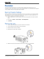
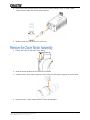
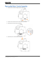
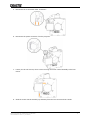
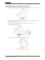
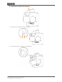
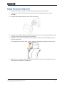
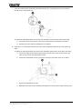
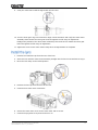
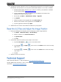
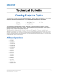
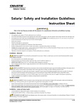
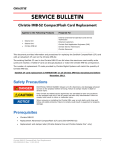
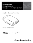
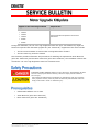
Applies to the Following Products CP2220 CP2230 CP4220 CP4230 D4K25 D4K35 Prepared For Internal and External Operators and Service Technicians During lens calibration, the 1.6-2.4:1 high brightness zoom lens (P/N: 108-336103-XX) might not function as expected with the Motor Upgrade kit (127-102104-XX). Symptoms of this issue include: The lens motor hesitates or stutters when moving backward or forward The lens zoom ring cannot be rotated This document provides information and procedures for installing the replacement Zoom Motor kit (P/N: 003-103912-XX) and the Motor Control kit (P/N: 003-101582-02). The installation of these kits corrects the 1.6-2.4:1 high brightness zoom lens movement issue. ELECTRICAL SHOCK HAZARD! Always turn off, disconnect, and disengage all power sources to the projector before servicing. Failure to comply results in death or serious injury. Only Christie accredited service technicians are permitted to open any enclosure on the projector and only if the AC power has been fully disconnected. Failure to comply could result in minor or moderate injury. Solaria Main Software v4.0 or later Zoom Motor kit (P/N: 003-103912-XX) Motor Control kit (P/N: 003-101582-02) Motor Upgrade Kit Update Service Bulletin 020-200262-01 Rev. 1 (01-2014) 1 This section provides procedures for correcting the Motor Upgrade Kit functionality issue. The illustrations used in the procedures show a Christie CP4230 projector. For instructions that are specific to your projector model, see the projector Service Manual. Service permissions are required to complete this procedure. This procedure is not required if Solaria Main Software v4.0 or later is installed. The backup is only required if the software upgrade fails. To restore projector settings, see the projector User Manual. 1. Insert a USB flash drive into the USB port on the side of the projector touch panel controller (TPC). 2. On the TPC, tap Menu > Service Setup > File Management. 3. Tap Backup. 1. Turn the lamp off and allow it to cool for a minimum of 15 minutes. 2. Turn the projector off and disconnect it from AC power. 3. Remove the front shroud (if installed). 4. Disconnect the 2 zoom motor connectors. 5. Install a lens cap on the lens and then move the lens clamp to the open position. Motor Upgrade Kit Update Service Bulletin 020-200262-01 Rev. 1 (01-2014) 2 6. Pull the lens with the zoom motor out of the lens mount and then set it on a flat, stable surface with the wide end of the lens facing down. 7. Install a small lens cap on the rear of the lens. 1. Loosen the screw on the zoom motor clamp. 2. Slide the clamp upwards off the lens and set it aside. 3. Carefully lift the zoom motor assembly up and away from the zoom ring gear and set it aside. 4. Place the lens in a safe location where it cannot be damaged. Motor Upgrade Kit Update Service Bulletin 020-200262-01 Rev. 1 (01-2014) 3 1. Remove the 2 screws securing the focus motor cover. 2. Remove and set aside the focus motor cover and screws. 3. Disconnect the 2 focus motor connectors. 4. Disconnect the 2 vertical motor connectors. Motor Upgrade Kit Update Service Bulletin 020-200262-01 Rev. 1 (01-2014) 4 5. Disconnect the 2 horizontal motor connectors. 6. Disconnect the power connector from the projector. 7. Loosen, but do not remove, the 2 screws securing the motor control assembly to the lens mount. 8. Slide the motor control assembly up and away from the lens mount and set it aside. Motor Upgrade Kit Update Service Bulletin 020-200262-01 Rev. 1 (01-2014) 5 1. Align the replacement motor control assembly over the mounting screws on the lens mount. 2. Slide the mounting brackets on the motor control assembly over and down onto the mounting screws until it locks into position. 3. Tighten the 2 screws to secure the motor control assembly to the lens mount. 4. Connect the 2 focus motor connectors. 5. Secure the focus motor cover to the focus motor with 2 screws. Motor Upgrade Kit Update Service Bulletin 020-200262-01 Rev. 1 (01-2014) 6 6. Connect the 2 vertical motor connectors. 7. Connect the 2 horizontal motor connectors. 8. Connect the power connector to the projector. Motor Upgrade Kit Update Service Bulletin 020-200262-01 Rev. 1 (01-2014) 7 1. Rotate the lens zoom ring until it hits the stop closest to the zoom sensor flag. 2. Remove the 2 screws securing the zoom motor cover to the replacement zoom motor assembly. 3. Remove and set aside the zoom motor cover and screws. 4. Hold the zoom motor assembly in position and slide the zoom motor clamp downward onto the lens and over the base of the zoom motor assembly. 5. Position the zoom motor clamp locking screw next to the motor control assembly away from the lens locking lever. The image shows the zoom motor cover in position to assist with locating the locking screw. 6. Tighten the zoom motor clamp locking screw to secure the zoom motor assembly to the lens. Allow enough movement for adjustments. Motor Upgrade Kit Update Service Bulletin 020-200262-01 Rev. 1 (01-2014) 8 7. Verify the center of the zoom motor assembly sensor (A) is centered over the zoom sensor flag (B) on the zoom gear ring. To adjust the spacing between the zoom motor assembly sensor and the zoom sensor flag: a. Loosen the screw securing the zoom gear ring and move it backward or forward. b. Tighten the screw when the adjustment is complete. 8. Verify there is a small gap between the zoom motor assembly teeth and the zoom gear ring teeth. To adjust the spacing between the zoom motor assembly teeth and the zoom gear ring teeth: a. Loosen the zoom motor clamp locking screw and move the zoom motor left or right until you can access the adjustment screws. b. Loosen the adjustment screws (A) and (B) and move the zoom motor up or down. c. Tighten the adjustment screws d. Reposition the zoom motor assembly and tighten the zoom motor clamp locking screw. Motor Upgrade Kit Update Service Bulletin 020-200262-01 Rev. 1 (01-2014) 9 9. Verify the zoom motor shaft is aligned with the lens axis. 10. Turn the zoom gear ring to its maximum range in both directions and verify the zoom motor assembly teeth contact the zoom gear teeth throughout the full range of adjustment. Readjust the position of the zoom motor assembly if the teeth do not contact the zoom gear teeth throughout the full range of adjustment. 11. Tighten the screw on the zoom motor clamp when all adjustments are complete. 1. Remove the small lens cap from the rear of the lens. 2. Insert the lens with the zoom motor assembly straight into the lens mount without turning it. 3. Move the lens clamp to the locked position. 4. Remove the lens cap from the front of the lens. 5. Connect the 2 zoom motor connectors. 6. Secure the zoom motor cover to the zoom motor with 2 screws. 7. Connect the projector to AC power and turn it on. Motor Upgrade Kit Update Service Bulletin 020-200262-01 Rev. 1 (01-2014) 10 8. Upgrade the projector software. Service or Administrator permissions are required to upgrade the software. This procedure is not required if Solaria Main Software v4.0 or later is installed. a. Download Solaria Main Software v4.0 or later to a USB key. The software is available on the Christie website www.christiedigital.com. b. Insert a USB flash drive with the software into the USB port on the side of the projector touch panel controller (TPC). c. On the TPC, tap Menu > Administrator Setup > Upgrade. d. Tap Upload. e. Select the location of the upgrade file in the Drive Letter list. f. Browse to the location of the upgrade file in the Folder list. g. Tap the upgrade file and then tap Open. 9. Calibrate the lens. See the User Manual included with your projector 1. Reset your Intelligent Lens System (ILS) file settings to restore image positions: a. Tap Menu > Advanced Setup > ILS File Setup. b. Select an ILS file in the Current ILS File list. c. Tap Quick Reset. d. Tap Yes. 2. If necessary, adjust the position of the image on the screen: a. Tap the Lens Adjust ( b. Tap the Left ( right or left. c. Tap the Up ( up or down. d. Tap OK. ) or Right ( ) or Down ( ) icon on the Main screen. ) arrow icons in the Offset area to move the image ) arrow icons in the Offset area to move the image 3. Install the shroud (if removed). North and South America: +1-800-221-8025 or [email protected] Europe, Middle East, and Africa: +44 (0) 1189 778111 or [email protected] Asia Pacific: [email protected] Motor Upgrade Kit Update Service Bulletin 020-200262-01 Rev. 1 (01-2014) 11