1
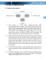
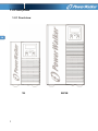
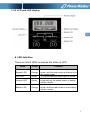
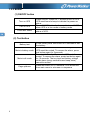
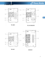
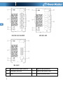
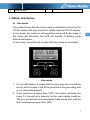
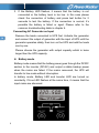
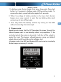
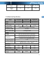
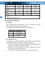
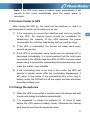
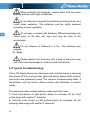
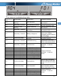
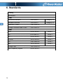
USER MANUAL ONLINE UPS PowerWalker VFI 1000T/E LCD PowerWalker VFI 2000T/E LCD PowerWalker VFI 3000T/E LCD EN Contents 1. Product introduction......................................................................... 2 1.1 Function description ...................................................................... 1 1.2 Front panel .................................................................................... 2 1.3 Rear panel ..................................................................................... 5 1.4 Mode description ........................................................................... 7 1.5 Product specification ................................................................... 10 EN 1.6 Communication port .................................................................... 12 2. Installation........................................................................................ 14 2.1 Safety Instructions for Installation ............................................... 14 2.2 Unpacking and Inspection........................................................... 15 2.3 Installation steps for standard model .......................................... 16 2.4 Installation for communication software (optional) ..................... 16 3. Operation ......................................................................................... 18 3.1 Operation Safety Instructions...................................................... 18 3.2 Start the UPS with mains (AC source) ........................................ 19 3.3 Start the UPS with battery (DC source) only .............................. 20 3.4 Connect loads to UPS................................................................. 21 3.5 Charge the batteries ................................................................... 21 3.6 Discharge the batteries ............................................................... 22 3.7 Test the batteries ......................................................................... 22 3.8 Turn off the UPS with mains (AC source) ................................... 23 3.9 Turn off the UPS with battery (DC) only...................................... 23 4. Maintenance..................................................................................... 24 4.1 Maintenance Safety Instructions................................................. 24 4.2 Typical Troubleshooting .............................................................. 26 4.3 Battery Maintenance ................................................................... 28 4.4 Contact the service centre .......................................................... 28 5. Transport and Storage .................................................................... 29 6. Standards ......................................................................................... 30 2 1. Product introduction 1.1 Function description EN This product is a true online double-conversion UPS (Uninterruptible Power Supply). It provides perfect protection for critical load such as computer system. It can eliminate almost all mains power disturbances. The input AC current can be corrected to a wave following the mains voltage, so it is a high power factor system. Through the PWM control technology, the output voltage can be a pure & stable sine wave AC voltage. When the mains input become abnormal, the controller will stop the AC/DC and start the DC/DC section immediately to make sure the DC/AC (inverter) section can continue to work. After the mains input come back to normal range, the DC/DC will be stopped and the AC/DC works again. So the load is always power-supplied through inverter without any interrupt if the UPS is turned on. The UPS also provides an internal bypass path so that the load can be powered by mains input directly when the UPS is off or failed. The UPS is equipped with an internal charger for batteries which charges the batteries when the mains are within a reasonable range under “bypass mode” or “line mode”. 1 1.2 Front panel 1.2.1 Front view EN 1K 2 2K/3K 1.2.2 LCD and LED display EN LED definition There are total 4 LEDs to indicate the status of UPS. Name Colour Bypass LED Orange Line LED Green Inverter LED Green Battery LED Orange Function To indicate that the UPS is in bypass mode, and the load current is directly from the mains power. To indicate that the mains input is normal. To indicate that the load current is supplied from the mains power or battery via the inverter. To indicate that the UPS is in battery mode, and the load current is from battery via the inverter. 3 1.2.3 Button (1) ON/OFF button Turn on UPS Turn off UPS Clear fault status Press ON/OFF button for 1 second to turn on UPS. UPS would send a beep to indicate the power-on status Press ON/OFF button for 1 second to turn off UPS when UPS is in line mode or battery mode. Press ON/OFF button for 3 seconds to clear the fault status of UPS. EN (2) Test button Battery test Mute in battery mode Mute in all mode Page up/down 4 In line mode, press test button for 2 seconds to test the battery. Press test button for 2 seconds in battery mode, UPS would be muted. To resume the alarm, press test button again for 2 seconds. Press test button for 10 seconds, UPS would be muted. To resume the alarm, press test button again for 10 seconds. The key tone and battery voltage under alarm (every second buzzer beep twice) cannot be muted. Press test button for 0.5 seconds, UPS would turn from main menu to sub-menu in sequence 1.3 Rear panel EN 1K-IEC 1K-UK 1K-SCHUKO 2K-IEC 5 EN 2K/3K-SCHUKO 2K/3K-UK 3K-IEC 6 1 Communication port (RS232) 5 Mains input protection 2 Intelligent card slot 6 Mains input power cord 3 Fan 7 Output terminal block 4 Output socket 1.4 Mode description Line mode Line mode means that the mains input is rectified/converted by the AC/DC section and then inverted to stable output by DC/AC section. In line mode, the output is well-regulated and good to the loads. If the mains get abnormal, the UPS will transfer to battery mode without interruption. In line mode, Line LED and Inverter LED are turned on constantly. Line mode 1. If Line LED flashes, it means that the input may have something wrong, such as input L and N line reversed or the grounding wire is not connected properly. 2. If the load level is higher than 100%, the buzzer will beep one every 0.5 second as a warning for the over-loading condition. The user should remove unnecessary loads one by one, until the load level become lower than 100%. 7 EN 3. If the Battery LED flashes, it means that the battery is not connected or the battery level is too low. In this case please check the connection of battery and press test button for 2 seconds to test the battery. If the connection is normal, it’s possible the battery is failed or aged. Please refer to the common troubleshooting table in chapter 4. Connecting AC Generator as Input Remove the loads connected to UPS first. Activate the generator and connect the output of generator with the input of UPS until the generator operates stably, then turn on the UPS and add the loads one by one. EN Please choose the generator with output capacity which is twice larger than the UPS capacity. Battery mode Battery mode means that the battery power goes through the DC/DC section to the inverter (DC/AC) and output a stable backup power when the mains are failed. If the mains recovered, the UPS will transfer to line mode without interruption. In battery mode, Battery LED and Inverter LED are turned on constantly. If Line LED flashes at the same time, it means that the input mains are abnormal. 8 Battery mode 1. In battery mode, Buzzer beeps once every 4 seconds. Press test button for 2 seconds in battery mode, UPS would be muted. To resume the alarm, press test button again for 2 seconds. 2. When the voltage of battery decline to the lower limit, buzzer beeps once every second to warn the low battery status and remind user to turn off the loads. 3. User may check the backup function by turning on the UPS without connecting the mains input. Bypass mode Bypass mode means that the UPS provides the power through the internal bypass path to load directly without any regulation. If the controller detects the mains is abnormal, it will shut off the output to protect the load. The bypass voltage/frequency range and default output status (on/off) could be set by software tool. In bypass mode, Line LED and Bypass LED are turned on constantly. Buzzer beeps once every 2 minutes. Bypass mode 9 EN 1. If Line LED flashes, it means that the input may have something wrong, such as input L and N line reversed or the grounding wire is not connected properly. 2. The description of other LEDs is the same as line mode. 3. UPS’s backup function is not enabled under bypass mode. 1.5 Product specification EN 1.5.1 Model description This manual is applicable to the following models: Model name Power rating PowerWalker PowerWalker VFI 1000T/E LCD VFI 2000T/E LCD 1000VA/800W 2000VA/1600W PowerWalker VFI 3000T/E LCD 3000VA/2400W 1.5.2 Environment specification Model PowerWalker VFI 1000T/E LCD Operating Temperature PowerWalker VFI 2000T/ E LCD PowerWalker VFI 3000T/ E LCD 0-40°C Storage Temperature -25-55°C <1000m @ full load <2000m @ 91%load Altitude <3000m @ 82%load <4000m @ 74%load Relative Humidity Noise Level 20%-90% <45dB @ 1 meter <50dB @ 1 meter from front panel from front panel 1.5.3 Mechanical Specification Model 10 PowerWalker PowerWalker PowerWalker VFI 1000T/E LCD VFI 2000T/E LCD VFI 3000T/E LCD Dimension (W×H×D) 144×229×345 190×328×393 190×328×393 (mm) Weight (Kg) 9.2 17.2 22.6 EN 1.5.4 Electrical Specification Model Power PowerWalker PowerWalker PowerWalker VFI 1000T/E LCD VFI 2000T/E LCD VFI 3000T/E LCD 1000VA/800W 2000VA/1600W 3000VA/2400W 5A 10A 14.3A Input Current (Max.) Voltage Range 80VAC-285VAC(Default 180-264VAC) Frequency Range 40-70Hz Input Power Factor ≧0.98 @ full load Output Voltage 200*/208*/220/230/240VAC (sine-wave) Synchronizing mains input @ line mode Frequency 50/60Hz ± 0.05 Hz @ battery mode Voltage Regulation ± 2% Overload Capacity 47s~25s linear @ 105%~150%; 25s~300ms linear @150%~200%; >200% : 200ms Efficiency Line Mode 89% 90% 90% Battery Mode 83% 83% 83% 24Vdc 48Vdc 72Vdc Battery & Charger @ 25℃ Total battery rating voltage 11 Backup Time (Full >4.5min >4.5min >4.5min Load) Recharge Time (to <7Hours <7Hours <7Hours 90%) Charging Current 1A 1A 1A (Max.) Discharging Current 53A 53A 53A (Max.) Rated Charging 27Vdc- 27.6Vdc 54Vdc- 55.2Vdc 81Vdc- 82.2Vdc Voltage *: If the rating output voltage is 200/208VAC, the rating power will be decreased to 90%. *. Can’t support half wave load. EN 1.6 Communication port 1.6.1 RS232 The communication port (RS232) is for the connection with PC which is installed with monitoring software. Pin assignment of the DB-9 connector is shown below: Pin# Definition 2 TXD (output) 3 RXD (input) 5 GND 1.6.2 Intelligent card Intelligent card - AS400 card, NMC card and CMC card are optional. The intelligent card is inserted into intelligent card slot. a- AS400 card: Monitor the UPS by using the AS400 management function if the system has AS400 interface. b- NMC card: Communication with the PC via internet for remote monitoring and control of the UPS. c- CMC card: a centralized-control card for remote monitoring 12 Note: Please contact with distributor or service center for detail information about intelligent cards. EN 13 2. Installation 2.1 Safety Instructions for Installation Please read the following safety instructions before installation! EN Installation Personnel This product must be installed only by qualified or professional personnel accord to safety instructions! Installation Environment Do not install and operate the UPS if there is water condensation which may occur if the UPS is moved suddenly from a cold environment to a warm one. The UPS must be absolutely dry before being installed and operated. Please allow an acclimatization time of at least 2 hours. Otherwise hazard of electric shock may exist! Do not install the UPS in the environment where it is damp or would be exposed to direct sunlight or heat. Ensure the UPS is far away from water, inflammable gas and corrosive agents. Do not block the air vents on the housing of UPS. The UPS must be installed in a location with good ventilation. Ensure enough space on each side for ventilation. 14 Wiring & Grounding Installation and Wiring must be performed in accordance with the local electrical laws and regulations. The UPS must be securely grounded. If there are external UPS battery cabinets, please make sure the battery cabinets have the equipotential earth bonding to the UPS main cabinet. Do not connect Input N wire and output N wire together. An appropriate switch device as backup protection for over-current or short-circuit should be provided in the input mains. Battery Strictly follow the principle of “same voltage, same type” when connecting multi battery packs in parallel. DC breaker or fuse must be used as a protection device between the external battery pack and the UPS. The specification of protections must match the UPS’s specification. 2.2 Unpacking and Inspection 2.2.1 Unpack the package and check the contents. The shipped package contains: 1 UPS 1 user manual 15 EN 2.2.2 Inspect the appearance of the UPS to see if there is any damage during transportation. Do not turn on the unit and notify the dealer immediately if there is any damage or lack of some parts. 2.3 Installation steps for standard model 1) Make sure the wire / circuit breaker / socket are enough for the current rating of UPS to avoid the hazards of electric shock and fire. EN 2) Make sure the mains switch in the building is switched off. 3) Make sure the UPS is not turned on before wiring operation. 4) Turn off all loads firstly before connecting to the UPS. 5) Make sure the protective earth ground is correctly connected. 6) Connect the loads to the UPS through the outlet sockets. 7) Connect the input power cord of UPS to mains. 2.4 Software Installation WinPower is UPS monitoring software, featuring user-friendly interface to monitor and control your UPS. This unique software provides complete power protection for computer system while power failure. With the software users can monitor any UPS status on the same LAN. Furthermore, a UPS can provide security protection for more than one computer on the same LAN at the same time, such as shutting down system in security, saving application data and shutting down the UPS when power fails. Software Installation on your PC: 16 Connected by USB to a PC or notebook, the Software enables communication between the UPS and the computer. The UPS software monitors the status of the UPS, shuts down the system before the UPS is exhausted and can remotely observe the UPS via the Network (enabling users to manage their system more effectively). Upon AC failure or UPS battery low, UPS takes all necessary actions without intervention from the system administrator. In addition to automatic file saving and system shut-down functions, it can also send warning messages via pager, e-mail etc. Use the bundled CD and follow the on-screen instructions to install the software WinPower. Enter the following serial No. to install software: 511C1-01220-0100-478DF2A After the software is successfully installed, the communication with UPS has been established and an green icon will appear in the system tray. Double-click the icon to use the monitor software (as above). You can schedule UPS shutdown/start-up and monitor UPS status through PC. Detail instructions please refer to the e-manual in the software. Check www.powerwalker.com/winpower.html from time to time to get the latest version of monitoring software. 17 EN 3. Operation 3.1 Operation Safety Instructions Please read the following safety instructions before operation! EN Operation personnel The product is designed to be operated by general users. Operation warning Do not disconnect the earth wire on the UPS or the wiring terminals of grounding point at any time since this would result in the void of protective earth for the UPS and all connected loads. Do not try to disassemble the original part of the UPS before turning off and disconnecting it from the mains power & external battery. The UPS output socket may be electrically lived even if the UPS system is not connected to the mains power source. Make sure no liquid or foreign objects enter the UPS. Turn off the mains input switch and external battery switch immediately in the event of electric shock or fire closed to the UPS. 18 3.2 Start the UPS with mains (AC source) 1) Press the on/off button of the UPS front panel continuously for more than 1 second. The buzzer will beep once, the numeric area of LCD display will be lighted in sequence, after a few seconds of self-diagnosis, the UPS will be turned on in normal mode (line mode) and feed the output power with constant AC voltage, if the mains abnormal, UPS will shift into battery mode after self-diagnosis. 2) When the UPS enters line mode normally, the Inverter LED will be on, the Bypass LED and Battery LED will be off. There will be no beep from buzzer. 3) Press the battery test button for 0.5 second, UPS will show the information on LCD display as followings in a circular order. 19 EN 3.3 Start the UPS with battery (DC source) only This UPS can be started directly with DC source (battery), without AC source. 1) Press the on/off button of the UPS front panel continuously for more than 1 second. The buzzer will beep once, the numeric area of LCD display will be lighted in sequence, after a few seconds of self-diagnosis, the UPS will be turned to the battery mode and feed the output power with constant AC voltage. EN 2) When the UPS enters battery mode normally, the Inverter LED, and Battery LED will be on, the Bypass LED will off. 3) Press the battery test button for 0.5 second, UPS will show the information on LCD display as followings in a circular order. 4) To remind, UPS is under battery mode, it would send out beep once per 4 seconds, and user can enable/disable the buzzer by pressing battery test button for 2 seconds. 20 Note: If the UPS shuts down in battery mode automatically, it will resume to line mode automatically when the mains power is recovered. 3.4 Connect loads to UPS After turning the UPS on, the loads can be switched on, and it is recommended to switch on the loads one by one. 1) If it is necessary to connect the inductive load such as a printer to the UPS, the start-up power should be considered for determining the capacity of the UPS because the power consumption for inductive load during start-up could be large. 2) If the UPS is overloaded, the buzzer will beep twice every second as warning. 3) If the UPS is overloaded, some loads must be switched off or decreased immediately. It is recommended that the total loads connected to the UPS be less than 80% of UPS’s nominal output power rating to prevent the overloading during transient time and make the system more satiable. 4) If the overloading time is too long in line mode, the UPS will transfer to bypass mode. After the overloading disappeared, it will return to line mode. If the overloading time is too long in battery mode, the UPS will cut off the output and then shutdown according battery level 3.5 Charge the batteries 1) When the UPS is connected to normal mains, the charger will start to work and charge the batteries automatically. 2) It is suggested to charge the batteries for 10 hours at least before the UPS performs battery mode. Otherwise the backup time may be less than the expected value. 21 EN 3.6 Discharge the batteries 1) When the UPS is in battery mode, the buzzer will start beep according to different battery level. If the battery voltage drops to the alarming level, the buzzer will start beep rapidly (once every sec) to remind the user that the capacity of battery is too low and the UPS will be shutdown automatically soon. The user may switch off some non-critical loads to avoid the shutdown alarming and prolong the backup time. If no more non-critical loads can be switched off at that time, it’s better to shut down rest loads as soon as possible to protect the important loads or save data. Otherwise there might be a risk of data loss or damage loads by power interrupted after batteries discharged. EN 2) If the user found the buzzer is noisy under battery mode, the beep could be muted by pressing the test button for 2 seconds. 3) The backup time may vary from different environmental temperature and load type. 3.7 Test the batteries 1) The user may check the battery level or aging status when the UPS is under normal mode (line mode) by pressing test button for 2 seconds to enter battery test mode. 2) To make the system more reliable, the UPS will automatically perform battery test on regular basis. The default period is once per 90 days. 3) The battery test could be performed by sending command from monitoring software through the communication port. 4) If the UPS enters the battery test mode, the buzzer will beep once, and Line/Bypass/Inverter/Batter LEDs will be on and off one by one, which allows the user to check the battery level in this mode. 22 3.8 Turn off the UPS with mains (AC source) 1) To turn off the UPS, please press the ON/OFF button continuously for more than 1 second. 2) After pressing the button, UPS will have no output. If the mains power is normal, the Line LED will turn on. If there is no mains power, 10 seconds later, the numeric area of LCD display will be lighted in sequence, finally all the LCD and LED will be blackout, and UPS shutdown completely. Note 1: If the UPS’s bypass mode is enabled, the output socket will still have voltage directly from mains power after switching the UPS off. Note 2: There is a risk of power interruption for the loads if the UPS works in bypass mode. 3) To turn off the output of UPS and shut down the UPS completely, it is recommended the mains power of UPS shall be disconnected. Note: please make sure all the loads are prepared or turned off before shutting down the UPS. 3.9 Turn off the UPS with battery (DC) only 1) To turn off the UPS in battery mode, please press the ON/OFF button continuously for more than 1 second. 2) After pressing the ON/OFF button, the buzzer will sound beep once. The numeric area of LCD display will be lighted in sequence, finally all the LCD and LED will be blackuot, and UPS shutdown completely Note: please make sure all the loads are prepared or turned off before shutting down the UPS. 23 EN 4. Maintenance 4.1 Maintenance Safety Instructions Please read the following safety instructions before maintenance! EN Maintenance Personnel This product must be maintained only by qualified professional personnel accord to safety instructions! Risk of electric shock No matter the UPS is connected to the mains power or not, the output may have electricity. The parts (battery, capacitor) inside the unit may still have hazardous voltage after turning off the UPS. Make sure to disconnect the batteries before carrying out any kind of maintenance or repair. The battery may result in electrical shock. Verify that no voltage between the battery terminals and the ground is present before maintenance or repair. In this product, the battery circuit is not isolated from the input voltage. Hazardous voltages may occur between the battery terminals and the ground. Verify that no hazardous voltage exists in the energy storage capacitor before maintenance or repair. 24 Remove all jewellery, wristwatches, rings and other metal personal goods before maintenance or repair. Only use tools with insulated grips and handles when maintaining or repairing. Battery EN CAUTION: Only qualified personnel can replace the batteries! A battery can present a risk of electrical shock and high short circuit current. The following precautions should be observed when working on batteries. a) Remove watches, rings or other metal objects. b) Use tools with insulated handles. c) Wear rubber gloves and boots. d) Do not lay tools or metal parts on top of batteries. e) Disconnect the charging source prior to connecting or disconnecting battery terminals. f) Determine if battery is inadvertently grounded. If inadvertently grounded, remove source from ground. Contact with any part of a grounded battery can result in electrical shock. The likelihood of such shock can be reduced if such grounds are removed during installation and maintenance (applicable to equipment and remote battery supplies not having a grounded supply circuit). Do not short the positive and negative of the battery electrode. Batteries have a high short-circuit current and may cause a risk of serious shock or fire. 25 When changing the batteries, replace them with the same quantity and the same type of batteries. Do not attempt to dispose the batteries by burning them as it could cause explosion. The batteries must be rightly deposed according to local regulation. Do not open or destroy the batteries. Effluent electrolyte can cause injury to the skin and eyes and may be toxic to the environment. EN Do not dispose of batteries in a fire. The batteries may explode. Fuse Please replace the fuse only with a fuse of the same type and of the same amperage in order to avoid fire hazards. 4.2 Typical Troubleshooting If the LCD display shows any abnormal code, and the buzzer is alarming, that means UPS is running under abnormal status; please firstly analyze and resolve the problem by using ”The common troubleshooting table”, if the problem can’t be solved, please contact with distributor or service center. The abnormal codes include warning codes and fault codes: A: Fault code shown as right picture below for example. All the Fault codes begin with capital ‘F’ character. B: Warning code shown as left picture below for example. All the warning codes begin with capital ‘A’ character. 26 The common troubleshooting table: Warning/fault code Buzzer alarm Signification A04 Decide by other warning Line abnormal A07 Beep every 2 minute L/N connection reverse A08 Decide by other warning Bypass abnormal A10 Beep every 1 second Battery abnormal or disconnect A11 Beep every 1 second Battery voltage low A12 Continuously beep Battery voltage over charged A15 Beep every 1 second Overload warning A16 Beep every 1 second Fan abnormal A18 F01 F02 F03 F05 F06 F07 F08 F10 Continuously beep Continuously beep Continuously beep Continuously beep Continuously beep Continuously beep Continuously beep Continuously beep Continuously beep Charger abnormal Bus Soft Start up fail Bus voltage too high Bus voltage to low Bus short Inverter Soft Start up fail Inverter voltage too high Inverter voltage too low Output short F22 Continuously beep Overload fault F23 Continuously beep Over temp fault F29 F55 F57 F59 F62 Continuously beep Continuously beep Continuously beep Continuously beep Continuously beep Converter fail NTC open Battery damaged Battery over charged Inverter capacitor open Correction method Input line abnormal, wait for line resume Please check L/N and the ground connection is OK Input line abnormal, wait for line resume Please check battery connection is OK Please re-charger battery before use, if battery damaged, please contact to service people Belong to UPS normal protection behavior Please check the power connected to UPS, and load off the unnecessary device Please contact the distributor or service center Please contact the distributor or service center Load off the unnecessary device, make sure the load power lower than the rating power Please make sure the intake wasn’t blocked, and the indoor temp wasn’t to high Please contact the distributor or service center 27 EN 4.3 Battery Maintenance 1) EN 2) 3) 4) 5) The battery used for standard models are valve regulated sealed lead-acid maintenance free battery. It shall be charged regularly in order to maximize the expected life for the battery. When being connected to the mains power, whenever the UPS is turned on or not, the UPS keeps charging the batteries and also offers the protective function of overcharging and over-discharging. The UPS shall be recharged once every 4 to 6 months if it is not going to be used for a long time. In the regions with hot climates, the battery should be recharged/ discharged every 2 months. The recharging time should be >12 hours. In normal conditions, the battery life lasts 3 to 5 years. If the battery is found in bad condition, earlier replacement is recommended. Do not replace the battery individually. All batteries must be replaced at the same time following the instructions of the supplier. 4.4 Contact the service centre When contact with distributor or service center for troubleshooting, please provide the following information: 28 1) Model name of product 2) Serial number of product 3) The date when the problem found 4) LCD display status 5) Buzzer alarm status 6) Mains power condition 7) Load type and capacity 8) Environment temperature, ventilation status 9) Other information for complete description of the problem 5. Transport and Storage 5.1 Please transport the UPS only in the original packaging. 5.2 The UPS must be stored in the room where it is ventilated and dry. EN 29 6. Standards * Safety EN 62040-1 * EMI EN Conducted Emission..........................:EN 62040-2 Category C2 Radiated Emission.............................:EN 62040-2 Category C2 Harmonic Current...............................:EN 61000-3-2 Voltage Fluctuation and Flicker..........:EN 61000-3-3 *EMS ESD...................................................:EN 61000-4-2 Level 4 RS.....................................................:EN 61000-4-3 Level 3 EFT....................................................:EN 61000-4-4 Level 4 SURGE..............................................:EN 61000-4-5 Level 3 CS…………………………………..…..:EN 61000-4-6 Level 3 MS………………………………….….. EN 61000-4-8 Level 3 Voltage Dips………………………..…: EN 61000-4-11 Low Frequency Signals.....................:EN 61000-2-2 30