1
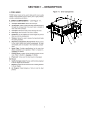
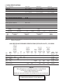
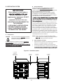
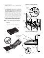
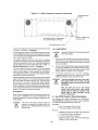
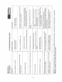
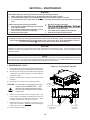
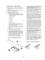
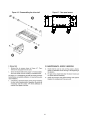
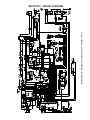
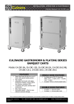
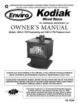
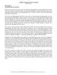
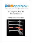
PS636 Series
Gas
Domestic & Std Export
ENGLISH
P/N 66639
December 2014 Rev. E
PS636 Series Gas Ovens
Model:
•
PS636G Gas
Combinations:
•
•
•
Single Oven
Double Oven (Two-Stack)
Triple Oven (Three-Stack)
OWNER'S OPERATING AND
INSTALLATION MANUAL
for domestic and standard export ovens
©2014 Middleby Marshall Inc.
is a registered trademark of Middleby Marshall, Inc. All rights reserved.
Middleby Cooking Systems Group • 1400 Toastmaster Drive • Elgin, IL 60120 • (847)741-3300 • FAX (847)741-4406
I. OVEN SPECIFICATIONS
Table 1-1 Dimensions
Single Oven
Overall Height
44″ (1118mm)
Overall Depth
44-1/2″ (1130mm)
Overall Length (w/o exit trays)
65-3/4″ (1670mm)
Conveyor Width – belt width is 24″25-1/2″ (648mm)
or 2 x 11” (279mm)
Recommended Minimum Clearances
Rear of Oven to Wall
0″ (0mm)
Control end of conveyor to Wall
2″ (50.8mm)
Non-control end of conveyor to Wall)
2″ (50.8mm)
Table 1-2: General Specifications PS636 GAS
24″ Belt
Double Oven
62-3/8” (1635mm)
44-1/2” (1130mm)
65-3/4″ (1670mm)
25-1/2″ (648mm)
or 2 x 11” (279mm)
Triple Oven
69-3/4″ (1171mm)
44-1/2” (1130mm)
65-3/4″ (1670mm)
25-1/2″ (648mm)
or 2 x 11” (279mm)
0″ (0mm)
2″ (50.8mm)
2″ (50.8mm)
0″ (0mm)
2″ (50.8mm)
2″ (50.8mm)
Weight
734 lbs. (333kg)
Rated Heat Input
75,000 BTU (18,892kcal, 22 kW/hr) Maximum Operation Temperature
600°F / 315°C
Air Blowers
Four Blowers at 3400 RPM (max)
Warmup Time
15 min.
Table 1-3: Electrical specifications for PS363G gas ovens
Main Blower Voltage
208-240VAC
Control Circuit
Phase
Freq
Voltage
208-240VAC
1Ph
50/60Hz
Current
Poles
Draw
4-3 Amp
Wires
2 Pole
3 Wire (2 hot, 1 gd)
Table 1-4: Gas orifice and pressure specifications for PS636G gas ovens
Gas Type
Main Orifice I.D.
PS745G
Natural
0.094 (2.375120mm)
Propane
0.057″ (1.45mm)
Supply (Inlet)
Pressure
Orifice (Manifold)
Pressure
Bypass
Pressure
8-12″ W.C. (19.9 - 29.9mbar)
3.5″ W.C. (8.7mbar)
0.3-0.35″ W.C. (0.8-0.9 mbar)
11-14″ W.C. (27.4 - 34.9mbar)
10.0″ W.C. (24.9mbar)
0.9-1.0″ W.C. (2.2-2.5 mbar)
IMPORTANT – Additional electrical information is provided on the oven’s serial plate, and on the wiring diagram inside the
machinery compartment.
GAS ORIFICE AND PRESSURE SPECIFICATIONS (PER OVEN CAVITY) - CE OVENS
AT,BG,CR
CZ,DK,EE
FI,GR,HR FI,CR,GR
BG,CY,CR
HU,IS,IE IE,HR,LU
CZ,DK,EE
IT,LV,LT NL,PL,SK SW,CHFI,GR,HR
NO,PT,RO SI,ES,CH AT,DK LV,LT,LU PL
SK,SI,ES
DE TR,GB,CY CY,CZ NO,FI MT,NL,NOAT,DE
Main SE,CH,TR
LU
BE CZ,DE,MTDE,MT NI,CR SK,SI,SEHU,SK
Gas
Orifice GB NLPL FR SK SK FR
TR CH
Typedia.
I2H
I2L
I2E
I2E+
I3P
I3P
I3B/P
I3B/P
I3B/P
G20
.0935″
Natural (2.375 mm)
20
--
mbar
G25
.0935″
--
Natural (2.375 mm)
20
mbar
BE,CY,CZ
EE,FR
GR,IE,IT
LT,LU,LV
PT,RO,SK
ES,CH
Orifice
Rated
GB,PL(Manifold)Heat
I3+
PressureInput
20
--
--
--
--
--
--
mbar
3.5” w.c.
8.7mbar
22kW
25
--
--
--
--
--
--
--
mbar
--
3.5” w.c.
8.7mbar
22kW
.
G30
.057″
--
--
--
--
--
--
28-30/50
30
37/50
28-30
10.0” w.c. 24.6kW
Butane
(1.45 mm)mbarmbar
mbarmbar
24.9mbar
G31
.057″
--
--
--
--
37
50
30
37/50
37
10.0” w.c. 22kW
Propane
(1.45 mm)mbar
mbar-- mbar
mbarmbar
24.9mbar
NOTE
Wiring Diagrams are contained in Section 5 of this Manual
and are also located inside the oven at the
bottom of the Control Panel.
Additional electrical information is provided on the oven's serial plate.
This Manual Must Be Kept For Future Reference
2
SECTION 2 – INSTALLATION
WARNING – After any conversions, readjustments, or service work on the oven:
• Perform a gas leak test.
• Test for proper combustion and gas supply.
• Test for correct air supply, particularly to the • Check that the ventilation system is in operation.
burner blower.
WARNING - Keep the appliance area free and clear of combustibles.
WARNING – The oven must be installed on an even (level) non-flammable flooring and any adjacent
walls must be non-flammable. Recommended minimum clearances are specified in the Description
section of this manual.
WARNING – Do not obstruct the flow of combustion and ventilation air to and from your oven. There
must be no obstructions around or underneath the oven. Constructional changes to the area where
the oven is installed shall not affect the air supply to the oven.
CAUTION: To reduce the risk of fire, the appliance is to be mounted on floors of noncombustible construction
with noncombustible flooring and surface finish and with no combustible material against the underside thereof, or on noncombustible slabs or arches having no combustible material against the underside thereof, such
construction shall in all cases extend not less than 12 inches (304mm) beyond the equipment on all sides.
CAUTION: For additional installation information, contact your local Authorized Service Agent.
NOTE – There must be adequate clearance between the oven and combustible construction. Clearance must
also be provided for servicing and for proper operation.
NOTE – An electrical wiring diagram for the oven is located inside the machinery compartment.
NOTE: All aspects of the oven installation, including placement, utility connections, and ventilation requirements, must conform with any applicable local, national, or international codes. These codes supersede the
requirements and guidelines provided in this manual.
NOTE: In the USA, the oven installation must conform to local codes. In the absence of local codes, gas oven
installations must conform with the National Fuel Gas Code, ANSI Z223.1. Gas and electric ovens, when
installed, must be electrically grounded in accordance with local codes, or in the absence of local codes, with
the National Electrical Code (NEC), or ANSI/NFPA70.
NOTE: In Canada, the oven installation must conform with local codes. In the absence of local codes, gas
oven installations must conform with the Natural Gas Installation Code, CAN/CGA-B149.1, or the Propane
Gas Installation Code, CAN/CGA-B149.2, as applicable. Gas and electric ovens, when installed, must be
electrically grounded in accordance with local codes, or in the absence of local codes, with the Canadian
Electrical Code
CSA C22.2.
NOTE: In Australia, the oven installation must conform with local codes. In the absence of local codes, gas
oven installations must conform with the requirements of AS5601/AG601, Gas, Electricity, and any other
relevant statutory regulations.
3
PS636 24” OVEN INSTALLATION
REQUIRED KITS AND EQUIPMENT
PS636
Gas Oven
Installation
Kit
PS636
Single Oven
Option Base w/
15” Legs,
Casters & Top
Kit
P/N 66129
PS636 Single Gas Oven
66331
1
PS636 Double Gas Oven
66332
PS636 Triple Gas Oven
66333
Type Of Installation
PS636
Double Oven
Option Base w/
15” Legs,
Casters & Top
Kit
P/N 66027
PS636
Triple Oven
Option Base w/
15” Legs,
Casters & Top
Kit
P/N 6xxxx
1
1
III. VENTILATION SYSTEM
B.
NOTE THAT THE HOOD DIMENSIONS SHOWN IN
FIGURE 2-5 ARE RECOMMENDATIONS ONLY.
LOCAL, NATIONAL AND INTERNATIONAL CODES MUST
BE FOLLOWED WHEN INSTALLING THE
VENTILATION SYSTEM. ANY APPLICABLE CODES
SUPERSEDE THE RECOMMENDATIONS SHOWN IN
THIS MANUAL. IN AUSTRALIA COMPLIANCE TO REGULATIONS AS5601/AG601 IS MANDATORY.
IMPORTANT
Where national or local codes repression equipment or other
supplementary equipment, DO NOT
mount the
equipment directly to the oven.
MOUNTING SUCH EQUIPMENT ON
THE OVEN MAY:
• VOID AGENCY CERTIFICATIONS
• RESTRICT SERVICE ACCESS
• LEAD TO INCREASED SERVICE
EXPENSES FOR THE OWNER
A.
sign. Consult the hood manufacturer or ventilation engineer
-
To avoid a negative pressure condition in the kitchen area,
return air must be brought back to replenish the air that was
exhausted. A negative pressure in the kitchen can cause
heat- related problems to the oven components as if there
were no ventilation at all. The best method of supplying
return air is through the heating, ventilation and air conditioning (HVAC) system. Through the HVAC system, the air can
be temperature-controlled for summer and winter. Return air
can also be brought in directly from outside the building, but
detrimental effects can result from extreme seasonal hot and
cold temperatures from the outdoors.
Requirements
CAUTION:
Recommendations
NOTE: Return air from the mechanically driven system
must not blow at the opening of the baking chamber.
Poor oven baking performance will result.
Gas oven installations REQUIRE a mechanically driven ventilation system with electrical
exhaust air sensing control.
C.
Other ventilation concerns
A mechanically driven ventilation system is STRONGLY
RECOMMENDED for electric oven installations.
•
Special locations, conditions, or problems may require the
services of a ventilation engineer or specialist.
PROPER VENTILATION OF THE OVEN IS THE RESPONSIBILITY OF THE OWNER.
•
Inadequate ventilation can inhibit oven performance.
•
It is recommended that the ventilation system and duct
hood manufacturer and/or HVAC engineer or specialist.
Figure 2-5. Ventilation System
6″ (152mm)
minimum
(Typical - both
ends of oven)
2″ (51mm)
minimum
5
2″ (51mm)
minimum
3″ (76mm)
minimum
IV. ASSEMBLY
Figure 2-6. Leg extension and casters installation
A.
Top Panel and Base Pad Assembly
1.
Install the four leg extensions onto the base pad using
the 3/8″-16 × 1″ screws, 3/8″ flat washers, and
3/8″ lockwashers supplied in the Base Pad Kit. See
sion face OUTWARDS. One rear leg should be attached
using three 3/8″-16 × 1″ screws and the 3/4″ eyebolt, as
shown in Figure 2-6. This eyebolt acts as the anchor point
for the restraint cable assembly (see Part C, Restraint
Cable Installation).
2.
1/2″
washer
1/2″ lock
washer
If your oven is equipped with the lower shelf, position it
in place as shown in Figure 2-6. Check that the lip on the
shelf faces DOWN. Seal joint between leg and shelf with
NSF listed silicone.
3.
Install one caster onto each leg extension, as shown in
Figure 2-7. Use the 3/8″-16 × 1″ screws, 3/8″
ers, and 3/8″ lockwashers supplied in the Installation Kit.
The locking casters should be installed at the FRONT of
the oven. The non-locking casters should be installed at
the REAR of the oven.
4.
Install the lower oven cavity onto the base pad.
See Fig 2-7.
5.
For single ovens ONLY:
1/2″-13 × 1-1/4″
hex screw
Install the top panel using the screws included in the base
pad kit, as shown in Figure 2-8. Then, skip ahead to Part
C, Restraint Cable Installation.
For double or triple ovens:
Continue on to Part B, Stacking. Note that the top panel
should NOT be installed for double and triple ovens until
after stacking the oven cavities.
Figure 2-7. Base pad Installation
Figure 2-8. Top panel installation
Bottom oven
cavity
#10-32 × 2-1/2″
screw length
#10-32 × 3/4″
screw length
Assembled
base pad
6
Top
panel
C.
NOTE: DO NOT install top panel onto double or triple
ovens until AFTER stacking the oven cavities. See
Part B, Stacking.
B.
Restraint Cable Installation
Because the oven is equipped with casters, a restraint cable
assembly must be installed to limit the movement of the
appliance without depending on the connector and the quick
disconnect device or its associated piping. One end of the
cable is anchored to the eyebolt on the rear surface of the
oven’s base pad, while the other is anchored to the wall.
See Figure 2-11.
Stacking
For single ovens, skip ahead to Part C, Restraint Cable
Installation.
IMPORTANT
Middleby Marshall STRONGLY RECOMMENDS that PS745
Gas oven cavities be stacked BY AUTHORIZED PERSONEL.
location. Adjust the bottom (hex) sections of the feet so that
front casters.
Contact your Middleby Marshall Authorized Service Agent for
complete stacking instructions.
Figure 2-10. Top panel installation
1.
Stack an oven cavity on top of the lower oven. Check
the following:
#10-32 × 2-1/2″
screw length
• All four sides of the lower lip (on the bottom edge of
the oven cavity) overlap the top of the lower oven
#10-32 × 3/4″
screw length
Top
panel
• The oven is level
•
See Figure 2-9.
2.
For triple ovens, repeat Step 1 to install the top
oven cavity.
3.
Install the top panel using the screws included in the base
pad kit, as shown in Figure 2-10.
Figure 2-9. Stacking
Figure 2-11. Installing the Restraint Cable
Restraint cable assembly
3/8″-18 × 1″
eyebolt on
rear leg
extension
3/4″ (19mm)
eyebolt
Wall of structure
7
D. Conveyor Installation
1.
2.
Figure 2-13. Conveyor placement
Unfold the conveyor as shown in Figure 2-12. Then,
begin to slide the conveyor into the end of the oven. The
conveyor can only be installed from the end of the oven
with the drive motor.
Crumb tray
support
bracket
Continue moving the conveyor into the oven until the frame
protrudes equally from each end of the oven. Check that
the crumb tray supports located on the underside of the
conveyor frame rest firmly against the lower end plugs,
as shown in Figure 2-13.
3.
When the conveyor is positioned properly, check for
freedom of movement of the conveyor belt by pulling it
for about 2-3 feet (0.6-1.0m) with your fingers. The drive
and idler shafts must rotate smoothly, and the belt must
move freely without rubbing on the inside of the oven.
4.
Check the tension of the conveyor belt as shown in
Figure 2-14. The belt should lift about 1″ (25mm).
DO NOT OVERTIGHTEN THE CONVEYOR BELT.
End plug
Conveyor
placed in
oven
NOTE: If necessary, the belt tension can be adjusted by
turning the conveyor adjustment screws, located at
the idler (non-control) end of the conveyor. See
Figure 2-14.
Figure 2-12. Conveyor installation
Folded
frame
Figure 2-14. Conveyor Belt tension
Idler end (with belt tension
adjustment screws)
1″ (25mm) vertical deflection
Adjustment
screws (2) on
idler end of
conveyor
Drive end (with
drive sprocket)
8
SECTION 4 - MAINTENANCE
WARNING
Before ANY cleaning or servicing of the oven, perform the following procedure:
1.
2.
3.
Switch off the oven and allow it to cool. Do NOT service the oven while it is warm.
Turn off the electric supply circuit breaker(s) and disconnect the electric supply to the oven.
If it is necessary to move a gas oven for cleaning or servicing, disconnect the gas supply before moving the
oven.
When all cleaning and servicing is complete:
1. If the oven was moved for servicing, return the oven
to its original location.
2. If the restraint cable was disconnected to clean or
service the oven, reconnect it at this time.
3. Reconnect the gas supply.
4.
5.
Reconnect the electrical supply.
line connections for leaks using approved leak test
substances or thick soap suds.
Turn on the electric supply circuit breaker(s).
Perform the normal startup procedure.
6.
7.
WARNING
Possibility of injury from moving parts and electrical shock exists in this oven. Switch off and lockout/tagout the
electric supply BEFORE beginning to disassemble, clean, or service any oven. Never disassemble or clean an
oven with the BLOWER ( ) switch or any other circuit of the oven switched on.
CAUTION
NEVER use a water hose or pressurized steam-cleaning equipment when cleaning this oven. To avoid saturating the oven
insulation, DO NOT use excessive amounts of water. DO NOT use a caustic oven cleaner, which can damage the bake
chamber surfaces.
NOTE
ANY replacement parts that require access to the interior of the oven may ONLY be replaced by a Middleby Marshall Authorized Service Agent. It is also strongly recommended that the 3-Month Maintenance and 6-Month Maintenance procedures
in this section be performed ONLY by a Middleby Marshall Authorized Service Agent.
I. MAINTENANCE - DAILY
A.
Check that the oven is cool and the power is disconnected,
as described in the warning at the beginning of this Section.
B.
Clean ALL of the cooling fan grills and vent openings with
a stiff nylon brush. Refer to Figure 4-1 for the locations of
the grills and vents.
C.
Clean the outside of the oven with a soft cloth and mild
detergent.
D.
Check that ALL cooling fans are operating properly.
Figure 4-1. Cooling Vents and Grills
Vents on
front panel
of oven
CAUTION: If a cooling fan is not operating correctly, it
must be replaced IMMEDIATELY. Operating the oven without adequate cooling
can seriously damage the oven's internal
components.
E.
Clean the conveyor belts with a stiff nylon brush. This
is more easily accomplished by allowing the conveyor to
run while you stand at the exit end of the conveyor. Then,
brush the crumbs off the conveyor as it moves.
F.
Remove and clean the crumb trays. If necessary, refer to
Figure 2-16 (in Section 2, Installation) when replacing the
crumb trays into the oven.
Fan grills (2) on rear
of oven and control
compartment
G. Clean the window in place.
18
Vent (1) on rear
of machinery
compartment
21
Middleby-Marshall Model Number PS636G208-240 Volt 50/60Hz, 1 Phase
SECTION 5 - WIRING DIAGRAM
23
NOTES
24
NOTES
25
WARNING
Improper installation, adjustment, alteration, service or maintenance
can cause property damage, injury or death. Read the installation, operating and maintenance instructions thoroughly before
installing or servicing this equipment.
NOTICE
During the warranty period, ALL parts replacement and servicing should be performed
by your Middleby Marshall Authorized Service Agent. Service that is performed by parties other than your Middleby Marshall Authorized Service Agent may void your warranty.
NOTICE
Using any parts other than genuine Middleby Marshall factory manufactured parts relieves the manufacturer of all warranty and liability.
NOTICE
Middleby Marshall reserves the right to change specifications at any time.
Middleby is proud to support the Commercial Food Equipment
Service Association (CFESA). We recognize and applaud
CFESA's ongoing efforts to improve the quality of technical
service in the industry.
Middleby Cooking Systems Group • 1400 Toastmaster Drive • Elgin, IL 60120 • USA • (847)741-3300 • FAX (847)741-4406
www.middleby-marshall.com